Physical and Mathematical Modeling of
non Transferred Plasma Torches
R. C.Favalli,R. N. Szente Departamento de Fsica Aplicada Instituto de Fsica da Universidade de S~ao Paulo P.O. Box 66318 - Cep 05315-900, S~ao Paulo, Brazil
ReceivedAugust14,1997
The main objective of this work is to obtain temperature and velocity proles of the plasma jet, including the electric arc region, generated by non transferred plasma torches. The proles are obtained from a numerical solution of the conservation equations which were used to describe the plasma ow. This modeling approach will help the development and optimization of plasma torches, saving time and reducing costs of an alternative empir-ical development; it could also give some insight on the phenomena occuring inside the torch. Fluid mechanics models for laminar and turbulent ows were adopted to simulate the plasma inside and outside the torch. Patankar's control volume method was chosen to solve the resulting coupled dierential equations. The method is very stable and requires less computational time than higher order methods, although it can be less accurate for some applications. A computer code was developed to simulate the jet ow of a plasma torch. The results obtained from this program compared very well with published ones, cor-roborating the assumptions of the present model and the numerical method. Temperature and velocity proles for a plasma torch with dimentions and operating conditions similar to the ones used in industrial applications of spraying were generated and analyzed. The plasma torch simulated had an electric arc of 100A, plasma gas ow rate of 20 l=min, cross section of 5:2mm and anode length of 13mm.
I. Intro duction
Thermal plasmas have been employed in an increas-ing number of industrial applications since their rst de-velopment in the early 50's. Typical applications of this technology include materials processing (spraying, pro-duction of ceramic parts, synthesis of compounds such as titaniun dioxide, silicon carbide, silicon nitride, su-perconductors) and metallurgy (blast furnaces, produc-tion of special steel and ferroalloys, cutting, recovery of metal nes). In the last ve years, thermal plasmas have been extensively employed to treat residues or re-mediate enviromental problems such as hospital waste, destruction of toxic materials, vitrication of asbestos, remelting of incineration ashes, treatment of galvanic sludges, mercury contaminated soils and many others [1-3].
Thermal plasmas are normally generated in an equipment called plasma torch which consists
essen-tially of two electrodes (cathode and anode); an elec-tric arc is mantained between the electrodes. A certain amount of gas is injected into the torch (in principle any gas can be used) receiving energy from the arc and generating the thermal plasma.
A specic torch design and operating conditions are normally needed for the dierent industrial application of this technology. This normally implies an empirical development of the equipment, resulting in high costs and long development period for the construction, mod-ication and tests of the specic equipment.
A possible alternative for reducing the development costs of a plasma torch is to understand the phenomena involved in the torch operation and, using mathemati-cal models and numerimathemati-cal schemes, solve the resulting equations. Not only will this approach reduce the time spent for developing the torch, but will reduce the di-rect costs involved in an empirical development. The
resulting physical and mathematicalmodels of the torch will hopefully be used for dierent applications, simu-lating dierent sets of operating conditions and torch geometries.
In this work we present a physical and mathemat-ical modeling of a non transferred plasma torch. The geometry of the plasma torch used in the simulations is described below. The models adopted to simulate the jet ow in the plasma torch and the results ob-tained from the computer program are shown after the description of the torch. The last section of the paper presents a summary of the main discussed aspects.
II. Non Transferred Plasma Torch
There are dierent types and geometries of plasma torches. The two main classes of plasma torches are the so called transferred and non transferred torches. In the former, the electric arc used to generate the plasma is mantained between one electrode of the torch (normally the cathode) and a piece of metal (or another conduct-ing material) that one wants to cut or melt, located outside the torch. Those torches are typically used for metallurgical processes such as ferroalloy production or tundish heating. The other type, the non transferred plasma torches, employs the two electrodes of the torch in order to mantain the electric arc, i.e., the electric arc strikes between the two electrodes of the torch and it is kept inside the torch. These torches are normally used for spraying, production of advanced materials, and the treatment of hazardous wastes. In this work we studied the non transferred plasma torch although the computer code developed can be easily adapted to simulating transferred torches.
The plasma torch simulated in this work is based on a previous torch developed for the processing of materi-als and for treating industrial residues [4]. The former torch had a central injection of particles (through the cathode) and an external magnetic eld was used to rotate the arc. We modeled here a more generic and simpler plasma torch, similar to the ones used in spray-ing (coatspray-ing), without the central injection of particles and the external magnetic eld. However the computer code developed here presents great exibility, allowing easy and fast modications in order to simulate other types of plasma torches as mentioned before.
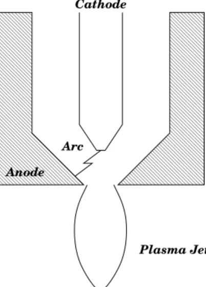
A schematic diagram of the plasma torch modeled here is given in Fig.1. An electric arc is mantained be-tween the two electrodes (cathode and anode); the gas
passes through the space between the electrodes and it is heated by the arc, forming the plasma jet.
Typical power levels of plasma torches used for spraying are between 10 and 100kW. Argon is nor-mally employed as the plasma gas since it is an easily ionized gas and it does not react with the material being treated or sprayed. The overall length of those torches varies between 5 and 40cm, with an external diame-ter between 1 and 10cm; dimensions of the torch are normally function of the power level of the equipment.
0000000 0000000 0000000 0000000 0000000 0000000 0000000 0000000 0000000 0000000 0000000 0000000 0000000
1111111 1111111 1111111 1111111 1111111 1111111 1111111 1111111 1111111 1111111 1111111 1111111 1111111
0000000 0000000 0000000 0000000 0000000 0000000 0000000 0000000 0000000 0000000 0000000 0000000 0000000
1111111 1111111 1111111 1111111 1111111 1111111 1111111 1111111 1111111 1111111 1111111 1111111 1111111
Anode
Cathode
Plasma Jet Arc
Figure 1. Schematic representation of the plasma torch modeled.
III. Theory
The physical and the mathematical models devel-oped in this work as well as the numerical method cho-sen to solve the set of the resulting governing equations are presented below, followed by the computational do-main and boundary conditions necessary for solving the equations and simulating the plasma jet.
III.1 Physical and Mathematical Modeling
plasma jet). This model is based on the following as-sumptions:
The plasma is optically thin, i.e., the black
body radiation emmited is not reabsorbed by the plasma;
The arc is in local thermodynamic equilibrium
(L.T.E.), i.e., all plasma components (electrons, ions and neutrons) have the same temperature and this condition prevails all over the plasma column, from the cathode to the anode;
The heat dissipation due to viscosity is negligible
because it is composed by second order terms;
The gravity eects are negligible due to the high
Froude number (310 6);
The arc is assumed to be steady and rotationally
symmetric.
These assumptions are commonly employed in plasma torch simulations [7-10].
The plasma jet is considered here to be a uid, in-stead of a statistical collection of particles (Boltzmann approach) and therefore the behavior of the plasma can be described using equations of state and conservation of mass, momentun, energy and current.
The set of dierential equations used to describe the physical model can be represented by a general trans-port equation.
1
r @ @r
(r v #) + @ @z
(u#) = 1 r @ @r r, # @# @r + @ @z ,# @# @z +S # (1)
where #is the dependent variable, ,
# is the corresponding diusion coecient, S
# is the source term,
uandv are
the axial and radial velocity components, is the mass density,z and r are the coordinates at axial and radial
directions. The left hand side is the convective part and the right hand side represents the diusive part and the sources.
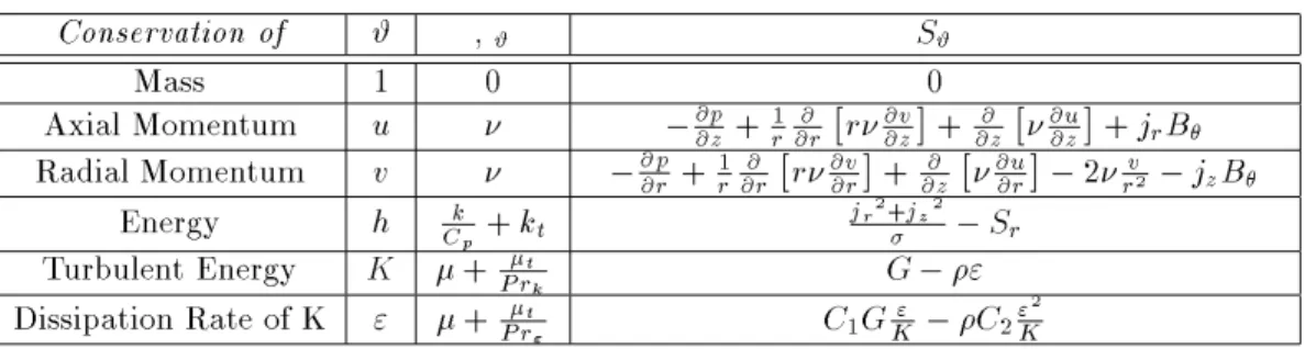
As mentioned before, equation 1 can represent the conservation of mass, momentum and energy of the plasma jet. The parameters of the governing equations for the plasma jet are given in Table 1.
Table 1:
Equations used for the model
Conservationof # , #
S #
Mass 1 0 0
Axial Momentum u ,
@p @z+
1 r @ @r r @v @z + @ @z @u @z +j r B
Radial Momentum v ,
@p @r + 1 r @ @r r @v @r + @ @z @u @r ,2 v r 2 ,j z B Energy h k Cp + k t jr 2 +jz 2 ,S r
Turbulent Energy K +
t Prk
G,"
Dissipation Rate of K " + t Pr " C 1 G " K ,C 2 " 2 K
In Table 1,pis the pressure, his the specic
enthal-phy, C
p is the specic heat, the thermal and electrical
conductivities are k and, respectively; is the
eec-tive viscosity,j zand
j
r are the axial and radial current
densities, B
is the azimutal component of the
mag-netic eld and S
r is the radiation heat loss. The last
two equations in the Table 1 are used for the turbulence modelK,"[11], where K is the kinetic turbulent
en-ergy and"its dissipation rate;and
tare the laminar
and turbulent viscosities; k
t is the turbulent thermal
conductivity. C 1, C 2, Pr k and Pr
"are constants of the K,"model (see Table below) andG, given
G= 2 t " @v @r 2 +v 2 r + @u @z 2 # + t @u @r +@v @z 2 (2) is the product of the eddy viscosity and viscous dissi-pation terms.
The turbulent viscosity (
t) and the thermal
con-ductivity (k
t) are dened using the values of
equa-tions, t= C K 2 " and k t= t Cp Pr t (3) where C and Pr
t are also constants of the turbulent
model adopted in this work. These constants are pre-sented in Table 2.
Table 2 Constant values of
K,"model
C 1 C 2 C Pr t Pr K Pr "1.44 1.92 0.09 0.9 1.0 1.3
Those values were suggested by Launder & Spalding [11]. According to those authors for axisymmetric jets
C and
C
2 should be modied as follows, C
= 0
:09,0:04f and C 2= 1
:92,0:0667f; (4)
where f = 2u , @u 0 @z , @u 0 @z 0:2
, is the jet
diame-ter, u
0 is the axial velocity at the center line and u
is the dierence between the center line and the free boundary velocities.
TheK,"model was chosen among several
turbu-lence models normally used to describe turbulent ows since"appears directly as an unknown in theK
equa-tion [12] as well as it represents nicely the characteristic of plasma ows.
The thermodynamic and transport properties of the plasma such as viscosity, density and electrical conduc-tivity were taken initially from the literature [13] and later modied [14]. Those properties were considered to be only temperature dependent.
In the energy equation the term for the energy trans-fer due the to electron ow was omitted since it is con-siderably smaller than the other terms of the equation [15]. Enthalpy was chosen instead of temperature to guarantee the conservation of energy in the calculations [15,16]. The temperature values, used for calculating the plasma transport and thermodynamic properties were obtained using the variation of enthalpy as a func-tion of temperature,
h= Z
C p
dT : (5)
It is necessary to take into account the current densi-ties and the azimuthal magnetic eld of the arc, consid-ered as source terms in the governing equations. Those
parameters were obtained from the current conserva-tion equaconserva-tion and one of the Maxwell's equaconserva-tions,
1 r @ @r r @ @r + @ @z @ @z
= 0 ; (6)
1
r @ @r
(r B ) = 0 j z ; (7) where
0 is the permeability of the freespace, is the
electrical potential and is the electrical conductivity.
The current densities are given by
j z= , @ @z and j r = , @ @r : (8)
Equation 6 does not present the conservative form of equation 1 but it was solved by the same algorithm used for solving the governing equations shown in Table 1. The Maxwell equation, for simplicity, was solved us-ing the nite dierence method. As mentioned before,
depends only on the plasma temperature.
III.2 Numerical Method
The control volume is a special version of the weighted residuals method. This method consists on dividing the calculation domain in control volumes around grid points. The set of governing equations, or a single dierential equation, is integrated over each control volume. This method guarantees the total con-servation of quantities such as mass, momentum and energy.
The governing equations shown in Table 1 were solved iteratively using Patankar's control volume ap-proach [17-19]. Although Patankar's method can present numerical diusion and is less accurate than higher-order methods, it is highly stable and converges easily while the higher order methods tend to have con-vergence problems and use more computational time.
The numerical iteration procedure is described be-low:
1. Initial guess values for p,u,v, T,K and";
2. Plasma transport and thermodynamic properties are calculated for each grid point;
3. After solving equation 6, the current densities j z
and j
r can be obtained from equation 8. The
4. Updated values of p, u, v, h (and consequently T), K and are obtained from the solution of
their respectives equations presented in the Table 1;
5. Return to the second step and repeat the proce-dure until convergence is reached.
III.3 Computational Domain and Boundary
Conditions
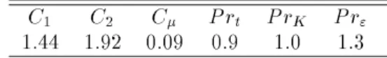
The computational domain used to solve the set of governing equations is shown in Fig.2. It is the upper half of a cross section of the plasma torch shown in Fig.1.
The computational domain is a simplied version of the plasma torch (Fig. 1), but it contains all the essential elements of that torch. Simplications were conducted for computational reasons. The dimensions of the torch simulated in this work were chosen in order to represent a commonly used spraying torch.
z r
H D C
B E
A
E’ A’
F G
10.3 mm 2.7 mm
O
Anode
Cath
37.0 mm 1.2 mm
5.2 mm 8.7 mm
Figure 2. Computational domain of the plasma torch.
The gas is injected at FG. It ows through the torch until the electric arc region AA'EE', where the gas is heated. EBCD represents the region of free-boundary (outside the torch) and the line AB is the simmetry axis.
The boundary conditions assumed for the computa-tional domain described in Fig.2 are the following.
1. Velocity.
The axial velocity (u) at the entrance of the torch
is determined specing the gas ow rate. The radial velocity (v) is zero there. No-slip
condi-tions are assumed in the electrodes region, i.e.,
u=v = 0. At the centre line AB, @u @r =
v = 0.
Free-boundary conditions for BC and CD are as-sumed, @(u)
@z = @v
@z = 0 and u=
@(r v )
@r = 0
re-spectively.
2. Enthalpy.
The boundary conditions for enthalpy are given in terms of temperature and later converted into the enthalpy of the respective gas using equation 5. The temperature at the entrance of the torch and at CD are assumed to be equal to the room temperature ('300K). The surface of the
cath-ode and of the ancath-ode are assumed to be at 3,000
K and 1,000K, respectively (taken into
consid-eration the interaction of the electric arc). In the centre line @h
@r = 0, and at BC
@h @z = 0.
3. Turbulence.
The plasma ow is laminar at FGsince the gas
has not been heated by the electric arc yet; then
K and"are given by [16]
K in=
i t(
u 2+
v 2+
w 2)
and " in= 3
K 3=2 in R
;
(9)
wherei t= 0
:003 is the turbulence intensity andR
is the radius of the inlet to the nozzle. In the line AB, @K
@r = @"
@r = 0 and at the free-boundaries BC
and CD, @K @z =
@"
@z = 0 and
K = "= 0,
respec-tively. Near the anode region, a wall-function is
used to obtain the values ofKand"(the laminar
eects are quite signicant there),
K p=
U 2 p
C
and " p =
U 3
0 y
p
; (10)
where 0= 0
:41 is the Von Karman constant,U
is the resultant frictional velocity given by thelaw ofthe wall,
U p U
= 1
0
ln EU
y
p
; (11)
where U
p is the parallel velocity to the wall, E= 9:973 is the roughness parameter for smooth
walls, andy
p is the distance from point
P to the
4. Electrical Potential.
The boundary condition for the electrical poten-tial is determined assuming a current prole at line AA' [16,20],
jz= j0e ,r =r
c ; (12)
where j0 and rc are constants which depend on
the current. For a blunter cathode tip and I =
200A, j0 = 100Amm
,2 and r
c = 1:5mm; for
I = 400A, j0 = 130Amm
,2 and r
c = 2:5mm.
These values are not the same if a sharp cathode is used: j0is slightly higher and rcsmaller. In the
line AB, @j z @r=j
r=0; jr=jz=0 in ED and = 0 at
the anode.
A summaryof the used boundary conditions is given in Table 3.
Table 2:
Boundary conditions used for the model
AB BC CD FG AA0 EE0 Anode Cathode
u @u=@r = 0 @(u)=@z = 0 0 u = cte 0 0
v 0 @v=@z = 0 @(rv)=@r = 0 0 0 0
h @h=@r = 0 @h=@z = 0 300K 300K 1;000K 3;000K
K @K=@r = 0 @K=@z = 0 0 Kin kp
" @"=@r = 0 @"=@z = 0 0 "in "p
@jz=@r = jr = 0 jg iv en jr;z = 0 0
IV. Results
The computer program was successfully tested in terms of iteration number and grid points. After 3,000 iterations for a grid with 100 points in the axial direc-tion and 60 points in the radial direcdirec-tion, the temper-ature and velocity proles remained unchanged even if a greater number of iterations or grid points were used. After the preliminary tests with the code, the results obtained in this work were compared with published ones. Examples of the temperature and velocity pro-les, as well as the electrical potential and axial current density proles, obtained using the computer code de-scribed previously and the torch shown in Fig. 2, are presented after the comparison with results from the literature.
IV.1 Comparisons
The results obtained from the computer code de-veloped here were compared with the results obtained from other researchers. Unfortunately, experimental re-sults for plasma velocities and temperatures inside the torch are extremelly dicult to be obtained due to the high temperatures and velocities found there.
The results of this work were compared with results
obtained from numerical simulations. It is quite di-cult to nd numerical simulations that include the elec-tric arc region. It is generally assumed a velocity and temperature prole at the nozzle exit, and using those proles simulations for the behaviour of the plasma jet are conducted. The shortback of that method is ob-vious; the velocity and temperature proles obtained depend entirely on the proles initially assumed.
The only published results found by the authors that could be compared to the present work are the ones of Bauchireetal[21]. The plasma torch simulated
in that work was similar to that of Fig.2; the dimen-sions of that torch were 9:1mm for the anode length and 3:4mm for the cross section of the torch; the operating conditions were I = 100A, gas ow rate of 3.4 l=min and argon was considered for both the plasma and the surrounding gas. Those were the same conditions and torch geometry reported by Bauchireetal[21], using a
similar numerical method as the one used here. The results obtained by Bauchire et aland in this
beginning of the computational domain represented by the point O in Fig.2.
0 10 20 30 40 50 Axial Distance (mm) 2500
7500 12500 17500 22500
Temperature (K)
Simulations Bauchire et al
0 10 20 30 40 50 Axial Distance (mm) 0
50 100 150 200
Velocity (m/s)
Simulations Bauchire et al
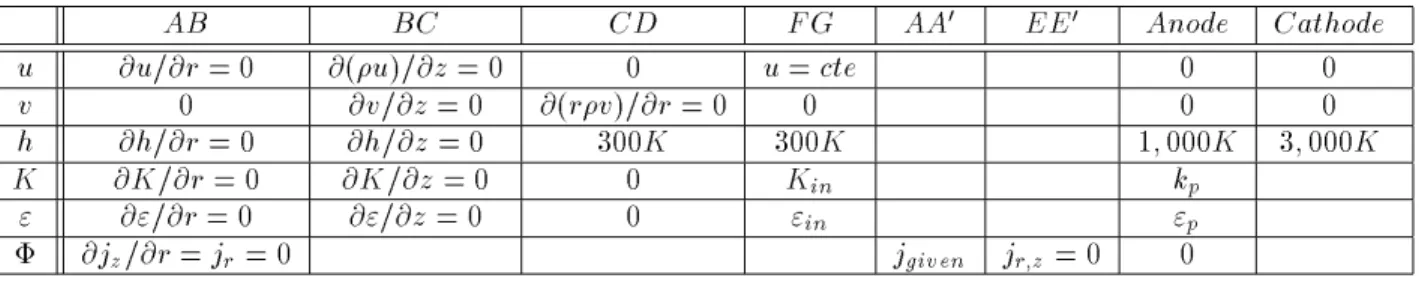
Figure 3. Temperatures and velocities at the centre line ob-tained from the present work (full line) and for Bauchire et al(dotted line).
The temperatures, as well as the plasma jet veloci-ties, reach their maximumat the vicinity of the cathode (3mm) due to the high current density existing there.
The dierences between the results of the two studies can be attributed to dierent assumptions such as the energy transported by the electrons travelling to the anode, considered to be negligible compared with other terms of the energy equation in this work. Another reason for the dierences could be the use of dierent values for the constants j0 and rc since they were not
available in Bauchire etal[21].
IV.2 Turbulence
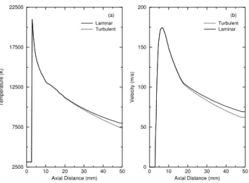
In Fig.4 we show the temperature and velocity pro-les at the centre line for laminar and turbulent ow as obtained in this work.
It can be seen that turbulence eects were negligi-ble. This conclusion is valid when using low current (< 300A), low gas ow rate (< 50l=min) and when the surrounding and the plasma gas are the same. Similar conclusions were also reached by Bauchire etal[21].
0 10 20 30 40 50 Axial Distance (mm) 2500
7500 12500 17500 22500
Temperature (K)
Laminar Turbulent
0 10 20 30 40 50 Axial Distance (mm) 0
50 100 150 200
Velocity (m/s)
Turbulent Laminar
(a) (b)
Figure 4. Temperatures (a) and velocities (b) at the centre line obtained for laminar (full line) and turbulent (dotted line) jet ow.
IV.3 Simulations of the non Transferred Plasma
Torch
Examples of results obtained in this study are pre-sented below. The gas was considered to be Argon for both the plasma and the surrounding gas. The plasma gas ow rate was 20 l=min and an electric arc of 100A was used for the examples given here. The cross sec-tion of the torch and the anode length are given in the computational domain. The temperature and velocity contours at the entrance of the torch, electric arc re-gion and free boundary rere-gion for the conditions given above are shown in Fig.5. The outermost contour is T = 2;000K, the innermost contour is T = 18;000K and the countour steps are 2;000K; the outermost con-tour of the velocity is 20m=s and the innermost is 240m=s; the contour steps are 20m=s. We can see from Fig. 5 that the hotest and fastest region of the plasma jet is inside the torch. Someone using the plasma torch for spraying or treating residues can take advantage of the high temperatures and velocities of the plasma jet found inside the torch by injecting the particles with the working gas.
0 5 10 15 20 25 30 35 40 45 50 0
5 10 15
R a d i a l D i s t a n c e ( m m )
Axial Distance (mm) (a)
0 5 10 15 20 25 30 35 40 45 50
0 5 10 15
R a d i a l D i s t a n c e ( m m )
Axial Distance (mm) (b)
Figure 5. Velocity (a) and temperature (b) contours of the plasma ow in the torch. The outermost contours are 2;000K and 20m=s and the innermost are 18;000K and 240m=s. The contour steps are 2;000K and 20m=s.
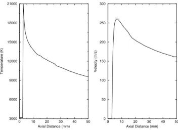
Near the cathode tip, the temperature reaches its maximumaround 21;000K; at the torch exit (13mm)
T = 13;500K and after 50mm, the temperature drops to 9;500K. The maximum velocity is reached near the cathode tip similarly to what was observed for the tem-perature; the value of the velocity is around 260m=s there and at the torch exit, the plasma jet velocity at the center line is 240m=s; at the end of the computa-tional domain the velocity is aproximately 160m=s.
The temperature decays faster inside than outside
the torch. This behaviour is probably due to the elec-trodes cooling (inside the torch) while in the free bound-ary region (outside the torch) the plasma jet cools o inuenced only by the surrounding gas.
Fig. 7 presents the radial temperature distribution at dierent axial positions. The temperature decays very quickly in this direction reaching values near the room temperature at r = 5mm (nozzle diameter).
0 10 20 30 40 50 Axial Distance (mm) 3000
6000 9000 12000 15000 18000 21000
Temperature (K)
0 10 20 30 40 50 Axial Distance (mm) 0
50 100 150 200 250 300
Velocity (m/s)
Figure 6. Temperature and velocity proles at the centre line for a plasma torch of 20 l=min of gas ow rate and
I= 100A simulated in this work.
0 1 2 3 4 5
Radial Distance (mm) 0
3000 6000 9000 12000 15000
Temperature (K)
14,5 mm 30,4 mm 50 mm
Figure 7. Radial prole of temperature of the torch in dif-ferent axial positions. z= 14:5mm(full line),z= 30:4mm
(dashed line) andz= 50mm(dot-dashed line).
caused by the failure of the L.T.E. assumption for tem-peratures below 9;000K and has been reported by other researchers [10,22,23].
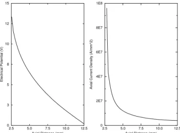
The computer code developed in this work calcu-lates also the electrical potential of the plasma. The value of the electrical potential for the operating con-ditions given above was around 13V , not including the anode and cathode falls. The electrodes fall should add to the electrical potential a value between 10 and 15V [7-9]. Plasma torches using Argon, with geometries and operating conditions similar to the ones simulated here, have overall voltages between 20 and 30V, in agreement with the results obtained here.
2.5 5.0 7.5 10.0 12.5 Axial Distance (mm) 0
3 5 8 10 12 15
Electrical Potential (V)
2.5 5.0 7.5 10.0 12.5 Axial Distance (mm) 0
2E7 4E7 6E7 8E7 1E8
Axial Current Density (A/mm^2)
Figure 8. Electrical p otential and axial current density at thecentrelineofthetorch.
The axial coordinate in Fig.8 starts at a distance of 2:5mm which coincides with the cathode tip. The axial current density shows an exponential behaviour and its maximum value occurs exactly at the cathode tip resulting on the increase of the plasma temperature to its maximum value as mentioned before.
V. Conclusion
We have developed physical and mathematicalmod-els to simulate the plasma ow through the torch, in-cluding the regions of the gas entrance and electric arc besides the free boundary region. The equations of the model were numerically solved using the control volume formulation of Patankar.
The computer code was tested and showed great exibility, allowing easy modication of the torch ge-ometry and operating conditions such as arc current and gas ow rate.
The results obtained from the computer program were initially compared with published data showing
good agreement. Examples of temperature and veloc-ity proles for the torch simulated in this work were given, indicating that the highest temperature occurs inside the torch and its value is around 21,000K. The velocity prole shows a similar behaviour observed for the temperature, with a maximum value of 260m/s. It was also seen that those proles (temperature and velocity) decay faster inside the torch; this fact is prob-ably due to the inuence of the cooling of the electrodes.
Acknowledgement
Financial support from CNPq and FAPESP through a scholarship for R. C. Favalli is gratefully ac-knowledged.
References
1. J. Szekely and D. Apelian, \Plasmaprocess in syn-thesis of materials," inMRS Symposium Proceed-ings(Anaheim), 1987.
2. EPRI Workshop, Research Opportunities for
Plasma Processing, (Palo Alto), 1987.
3. R. N. Szente, \Industrial applications of ther-mal plasmas,"inAIP Conference Proceedings, vol. 345, (Parana, BR), p. 487, 1995.
4. R. N. Szente, \Internal report," Tech. Rep. 217/94, Canadian Electrical Association, 1994. 5. Y. C. Lee, Modelling Work in Thermal Plasma
Processing. PhD thesis, Mechanical Engineering,
University of Minnesota, Minnesota, USA, 1984. 6. A. Mazza, Studies of an Arc Plasma Reaction for
Thermal Plasma Synthesis. PhD thesis,
Mechan-ical Engineering, University of Minnesota, Min-nesota, USA, 1983.
7. E. Pfender, Electric Arcs and Arc Gas Heaters. USA: Hirsh and Oskam Inc., 1978.
8. E. R. G. Eckert and E. Pfender, Advances in
Plasma Heat Transfer. Minnesota, USA:
Univer-sity of Minnesota, 1967.
9. J. Feinman, Plasma Technology in Metallurgical
Processing. Grand Junction, USA: J. Feinman
and Associates, 1987.
10. D. A. Scott, P. Kovitya, and G. N. Haddad, J. Appl. Phys.
66
, 5232 (1989).11. B. E. Launder and D. B. Spalding, \The numerical computation of turbulent ows,"Computer
Meth-ods in Applied Mechanics and Engineering,
3
, 26912. B. E. Launder and D. B. Spalding,
Mathemati-cal Models of Turbulence.London, UK: Academic
Press Inc., 1972.
13. S. Paik, G. Hawkes, and H. D. Nguyen, \Eect of working gases on thermal plasma waste treat-ment," Plasma Chemistry and Plasma Processing
15, 677 (1995).
14. M. I. Boulos, 1996. Private Communication, Uni-versity of Sherbrooke, Canada.
15. J. J. Lowke, P. Kovitya, and H. P. Schmidt, J. Phys. D: Applied Physics25, 1600 (1992).
16. A. B. Murphy and P. Kovitya, J. of Appl. Phys.
73, 4759 (1993).
17. S. V. Patankar, Numerical Heat Transfer and
Fluid Flow. New York, USA: McGraw Hill, 1980.
18. S. V. Patankar, \A numerical method for conduc-tion in composite materials, ow in irregular
ge-ometries and conjugate heat transfer," in Proceed-ings of the 6th International Heat Transfer
Con-ference, (Toronto, Canada), p. 297, 1978.
19. S. V. Patankar, Journal of Numerical Heat Trans-fer,4, 409 (1981).
20. K. C. Hsu, K. Etemadi, and E. Pfender, J. of Appl. Phys. 54, 1293 (1983).
21. J. M. Bauchire, J. J. Gonzalez, and A. Gleizes, "A physical modelling of a dc plasma torch," in
Pro-ceedings of 12th ISPC,vol. 3, (Minnesota, USA),
p. 1761, 1995.
22. J. D. Ramshaw and C. H. Chang, Plasma Chem-istry and Plasma Processing, 12, 299 (1992).