Journal of Applied Research and Technology 175
A Three-Dimensional Position Architecture Using Digital TDE Receiver
and Cylindrical Array Antenna
J. Mar*1, S. R. Wu2, Y. T. Wang3, K. C. Tsai4
1 2, 3, 4
Department of Communications Engineering Yuan-Ze University
Yuan-Ze University 135 Yuan-Tung Road, Jungli, Taoyuan 320, Taiwan, R.O.C. *[email protected]
1
Communication Research Center Yuan-Ze University
Yuan-Ze University 135 Yuan-Tung Road, Jungli, Taoyuan 320, Taiwan, R.O.C.
ABSTRACT
The robust three-dimensional position architecture is proposed in the paper, where the hybrid time difference of arrival (TDOA) and direction of arrival (DOA) position system was designed to backup the four-station TDOA position system. The digital time delay estimation (TDE) receiver is used for TDOA measurement and the cylindrical array antenna is used for DOA measurement. The general formula of linear phase compensation for cylindrical array antenna in horizontal plane is derived. The detection probability of the TDE receiver and the circular error probability (CEP) of the position systems over Rayleigh fading channel were numerically computed in three-dimensional space. Simulations indicate that the position accuracy of the four-station TDOA position system is degraded but the location function can be retained by the hybrid TDOA and DOA position system when any one of four-stations is out of work. Keywords: time delay estimation, circular error probability, time difference of arrival, direction of arrival.
1. Introduction
Since the United State Federal Communication Commission (FCC) in 1996 published the E-911 positioning standards, wireless location technology is extensively studied for its commercial value. The research of positioning method, including time difference of arrival (TDOA), direction of arrival (DOA) or hybrid TDOA/DOA algorithms, mostly bases on Gauss-Newton Interpolation (GNI) algorithm to estimate the location coordinates of mobile station (MS) in two-dimensional space [1]. The GNI algorithm can be applied to different types of measurements in the position system. For some applications, including land-to-air communications and passive radars; they need to provide the target locations in the three-dimensional space [2]. The multi-station TDOA position system, which employs optical communications to send the received signal of each station to a reference station to calculate the TDOA between the reference station and each station, has the advantages of high accuracy and low system complexity. Because the synchronization problem becomes simple and the common channel error can be eliminated among different stations.
A Three‐Dimensional Position Architecture Using Digital TDE Receiver and Cylindrical Array Antenna, J. Mar et al. / 175‐182
Vol. 11, April 2013 176
proposed digital TDE receiver using linear optimum filter is compared with typical TDE method [4] without using linear optimum filter to demonstrate its superiority. Section V concludes the paper. The formula of linear phase compensation for cylindrical array antenna in horizontal plane is derived in Appendix A.
2. Four-station TDOA location schemes 2.1 Principle of digital TDE receiver
Figure 1. Block diagram of digital TDE receiver. The TDE receiver, as shown in Figure 1, is implemented by a digital cross correlator in frequency domain to detect the position of the dominant peak energy in time domain. Here we assume that receiver 1 is the reference station. When the moving target source emits the signal s[n] in three-dimensional space, the received signal of the first receiver is given by
1[ ] [ ] 1[ ] , [0, ]
x n s n w n n M (1)
The received signals of other three receivers are given by
1
[ ] [ ] [ ] , [0, ] , 2,3,4
i i i
x n s n D w n n M i (2)
Then, the output of the cross correlation in frequency domain between station 1 and station i for i=2,3,4 is
1
1 2 *
1( ) 1( ) ( ) ( ) ( ) ( )
i
i
j D
M
i i s w w c
R k X k X k k e k k (3)
where Di1 is the discrete time delay between
receiver i and receiver 1, and
2
( ) ( )
s k S k (4)
1
* 1
( ) ( ) ( )
i
w w k W k W ki (5)
2 1
* *
1( ) ( ) ( ) ( )
i
j D
M
c W k S k e W k S ki (6)
The typical TDE using cross correlation of wide-band signals has been analyzed in [4], where the linear optimum filter was not included in the design.To reduce the occurrence of false peak due to the channel effect, a linear optimum filter is designed to maximize the expected signal peak relative to the output noise. The transfer function of the optimum filter is given by [5]
1 2 2 1
( ) ( )
[ ( ) ( )] [ ( )( ( ) ( ))]
s
W W s W W
k H k
k k k k k (7)
Where
1 1
2 2
2
2 1
2 2
( ) [ ( )] [ ( ) ]
( ) [ ( )] [ ( ) ]
( ) [ ( )] [ ( ) ]
s s
W w
W w
k E k E S k
k E k E W k
k E k E W k
(8)
The correlation output between receiver i and receiver 1 in time domain is determined by
1
[ ]i { i( ) ( )}
y l IFFT R k H k (9)
Then the discrete time delay between receiver i and receiver 1 is estimated at a peak energy discrete time positionli Di1 , i 2,3,4. The initial target location is solved by three hyperbolic equations.
2 2 2
,1 1 1 1
2 2 2
( ) ( ) ( )
( ) ( ) ( )
for 2,3,4
i
i i i
r x X y Y z Z
x X y Y z Z
i
(10)
where (X Y Zi, ,i i)and(X Y Z1, ,1 1)are the coordination
of theithand the1threceivers; ( , , )x y z is the target location. ri,1can be obtained from the measured
time delay between receiver i and receiver 1.
1
1
,1 1
,1 ( )
i
i
i i
i s
cD
r c c r r
A Three‐Dimensional Position Architecture Using Digital TDE Receiver and Cylindrical Array Antenna, J. Mar et al. / 175‐182
Journal of Applied Research and Technology 177 where N is the size of the fast Fourier transform
(FFT) and fs is the sampling frequency of the analog-to-digital converter. The target location in the three dimensional space is calculated by solving three hyperbolic of Eq.10. Therefore, the measured TDOA values are expressed as
i,1ri,1 ci1 i 2,3,4 (12)
2.2 GNI algorithm [1][2]
The GNI is an iteration algorithm, which uses the least square error (LSE) method to correct the initial estimated target location in the iteration until the error approaches zero. If guesses of the true initial target location (x y zv, v, v)is estimated using four-station TDOA method, by means of the first order Taylor expansion, the position equation is expressed in matrix form.
A z e (13) where
2 1 2 1 2 1
2 1 2 1 2 1
3 1 3 1 3 1
3 1 3 1 3 1
4 1 4 1 4 1
4 1 4 1 4 1
v v v v v v
v v v v v v
v v v v v v
x X x X y Y y Y z Z z Z
cr cr cr cr cr cr
x X x X y Y y Y z Z z Z
A
cr cr cr cr cr cr
x X x X y Y y Y z Z z Z
cr cr cr cr cr cr
(14)
2,1 2,1
21 3,1
3,1 31
41 4,1
4,1
( , , )
( , , )
, ,
( , , )
v v v
x
v v v
y
z
v v v
r x y z
c
r x y z
z e
c
r x y z
c
(15)
where
2 2 2
( ) ( ) ( )
for 1,2,3,4
i v i v i v i
r x X y Y z Z
i
(16)
e is a measurement error vector and is an estimated position error vector in the iteration.
i1 , 2,3,4i are identical independent distributed (IID) random variable with zero mean and covariance matrix R0of measurement error.
2 21
2
0 31
2 41
0 0
0 0
0 0
R (17)
where 2
1 , 2,3,4
i i are the variance of TDOA
measurement error. Then, the correction error at each step is
1 1 1
[ T ] T
A R A A R z (18)
Thus, the next estimated target location is replaced witxv xv x , yv yv y , zv zv z.As soon
as approaches to zero, the error covariance matrix becomes
2 2 2
2 2 2
0
2 2 2
x xy xz
xy y yz
xz yz z
Q (19)
For estimating three-dimensional target position, the accuracy of the position estimation is evaluated by the circular error probability (CEP) [2][6] in xy-axis and xz-xy-axis, which is a function of Q0. When the calculated errors are no more than 11%, the CEPs in xy-axis and xz-axis are approximated by
2 2
( ) ( ) ( )
CEPxy z (3 / 4) axy z bxy z (20) where
2 2 2
( ) ( ) 2
( ) 2 2 2 2 2 2 1/ 2
( ) ( ) ( )
2 2 2
( ) ( ) 2
( ) 2 2 2 2 2 2 1/ 2
( ) ( ) ( )
2{ }
{ [( ) 4 ] }
2{ }
{ [( ) 4 ] }
x y z xy z
xy z
x y z x y z xy z
x y z xy z
xy z
x y z x y z xy z
a
b
(21)
A Three‐Dimensional Position Architecture Using Digital TDE Receiver and Cylindrical Array Antenna, J. Mar et al. / 175‐182
Vol. 11, April 2013 178
3. Hybrid three-station TDOA and DOA position system
3.1 Algorithm
For hybrid three-station TDOA and DOA position system, the target location can be estimated by the same procedure as the four-station TDOA position system except changingEqs.14 and 15 as follows.
2 1 2 1 2 1
2 1 2 1 2 1
3 1 3 1 3 1
3 1 3 1 3 1
1 1
2 2
1 1 1 1
2 2 2
( )
0
( )( ) ( )( )
v v v v v v
v v v v v v
v v
xy xy
xy
v v v v
xyz xy xyz xy xyz
x X x X y Y y Y z Z z Z
cr cr cr cr cr cr
x X x X y Y y Y z Z z Z
cr cr cr cr cr cr
A
y Y x X
r r
r
x X z Z y Y z Z
r r r r r
(22) 2,1 2,1 21 3,1 3,1 31 1 1 1 1 1 ( , , ) ( , , ) , ,
tan ( )
tan ( )
v v v
v v v
x y v e z v v e xy
r x y z
c
r x y z
c z e y Y x X z Z r (23) where
2 2 2
( ) ( ) ( )
for 1,2,3
i v i v i v i
r x X y Y z Z
i
(24)
2 2 2
1 1 1
( ) ( ) ( )
xyz v v v
r x X y Y z Z (25)
2 2
1 1
( ) ( )
xy v v
r x X y Y (26)
The DOA measurement values in horizon and elevation are defined as
e (27)
e (28)
By means of the first order Taylor expansion, the true DOA angles in horizon and elevation are given by [2]
1 1 1 1 1 1
2 2
1 1
tan ( ) tan ( v ) v v
v xy xy
y Y y Y y Y x X
x y
x X x X r r
(29) 1 1 2 2 1 1
1 1 1 1
2
1 1
2 2
tan ( )
( ) ( )
( )( )
tan ( )
( )( )
v v v
xy xyz xy
xy
v v
xyz xy xyz
z Z
x X y Y
z Z x X z Z
x
r r
r
y Y z Z
y z r r r r (30) 2
and 2
are the variance of measured DOA errorsand , respectively.
3.2 Cylindrical Array Antenna
A M×L cylindrical array antenna is proposed to generate three-dimensional beam pattern with equal horizontal beamwidth for hybrid three-station TDOA and DOA position system.A general formula of linear phase compensation for N-element sub-array of M-element cylindrical sub-array antenna in horizontal plane is derived in Appendix A. When N is even, the time delay compensation for the sub-array antenna is summarized by
1 1 _ 1 2sin , 1,2,..., 1
2 2
2
sin , , 1,..., 2
2 2 2
0 , 0, 1
i i n N i d even n
d N N
n i
c M
d N N N
t n i N
c M
i N
(31)
The separation distances among the neighbouring elements of the non-uniform linear sub-array are
2
cos , 1,2,..., 1
2 2
2
_ cos , , 1,..., 1
2 2 2
0 , 0
i
N N
d i i
M
N N N
d even d i i N
M
i
(32)
A Three‐Dimensional Position Architecture Using Digital TDE Receiver and Cylindrical Array Antenna, J. Mar et al. / 175‐182
Journal of Applied Research and Technology 179 a sub-array with six omni-directional elements and
Chebyshev weightings In = [0.36, 0.6, 1, 1, 0.6,
0.36] is chosen to simulate the beam pattern[7]. The multimode DBF consists of a multiple beam (MB) and DOA modes. For MB mode, the output of each antenna element is subdivided into N independent signals by a (N-1)-way power divider. After the linear phase compensation, N independent signals are obtained from N adjacent elements and combined with associated weightings to generate a beam pattern of the N-element sub-array with the -20dB side lobe level in horizontal plane. The M-element array yields M beams to cover the 360° in azimuth. Each of the M beams is pointed in a fixed direction.
The amplitude comparison DOA mode [7] uses two neighbouring beams of the multi-beam antenna array with equal beam width to receive the target signal simultaneously. The signal amplitudes simultaneously received from two neighbouring beams are compared to obtain a difference signal. The measured difference signal power corresponding to the DOA of the signal from an air target is pre-stored in a look-up table of memory. The accuracy of amplitude comparison DOA mode is determined by the angular slope, which is defined as the rate of change in the power of the difference signal generated from the two neighbouring beams to the spatial angle. The more angular the slope is, the greater the accuracy of the DOA mode will be. The multi-beam antenna array is designed with the equal beam width so the amplitude comparison DOA mode can achieve the same accuracy as the DOA estimation in different directions.
4. Simulations
Simulations are performed to demonstrate the accuracy of the four-station TDOA and hybrid TDOA and DOA position systems. The 2048-point sampled orthogonal frequency division multiplexing waveform (OFDM) [8] is used to simulate target emitted signal over a two-ray Rayleigh fading channel [9]. The size of FFT is 4096 points. The TDOA measurement error is assumed to be Gaussian distributed with N (0, 10 nsec). For a 16×6 cylindrical array antenna, the horizontal antenna beamwidth is 23.4° and the elevation
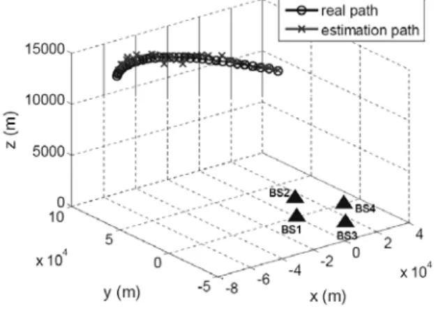
antenna beamwidth is 19.4°.The DOA measurement errors in horizon and elevation angles are uniformly distributed in (-11.7°, 11.7°) and (-9.7°, 9.7°),respectively. The coordinates of four stations and a three dimensional target trajectory are shown in Figure 2, where the coordinates of four stations expressed in unit of meter are station 1 (0,0,0), station 2 (15000,26000,0), station 3 (15000,-26000,0), and station 4 (30000,0,0), respectively, the initial target location is (-70000,70000,13716),the inter-distance of four stations is 30Km, the distance between the station 1 and the initial target location is 100 Km. It is assumed that the target speed is 1102.6 Km/hr, the stations receive the signal emitted from target once per 3 Km, and the target trajectory equation is given by
5 2
2.9761904 10 2.940476 10000 13716
y x x
z
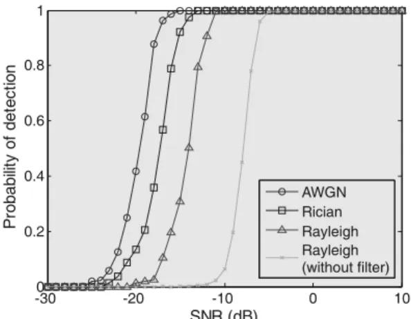
(33) Figure 3 shows that when the SNRs of receiver with linear optimum filter are -12.7dB, -15.45dB, and -18.03dB in Rayleigh, Rician, and AWGN channels, respectively, the time delay can be successfully measured with detection probability Pd=0.9 and false alarm probability PFA=10
-4
. The proposed method is compared with the typical method [4] in which the linear optimum filter is not applied to TDE receiver. As shown in Figure 3, the SNR of receiver without linear optimum filter is -7dB in Rayleigh channel for Pd=0.9 and PFA=10-4.
A Three‐Dimensional Position Architecture Using Digital TDE Receiver and Cylindrical Array Antenna, J. Mar et al. / 175‐182
Vol. 11, April 2013 180
-300 -20 -10 0 10
0.2 0.4 0.6 0.8 1
SNR (dB)
P
robabi
lit
y
of
det
ec
ti
on
AWGN Rician Rayleigh Rayleigh (without filter)
Figure 3. Detection probability for TDE measurements. The CEPxy and CEPxz of the four-station TDOA
position system and the hybrid TDOA and DOA position system operated in Rayleigh fading channel are shown in Figures 4 and 5 for SNR=-12.7dB, respectively. The minimum and maximum CEP values are listed in Table 1, which demonstrates that the accuracy of the four-station TDOA position system is better than the hybrid TDOA and DOA position system.
0 5 10 15 20 25 30 35
0 500 1000 1500 2000 2500 3000 3500 4000
iteration
CE
P xy
(m)
Hybrid TDOA+DOA 4-station TDOA
Figure 4. CEPxy comparison.
0 5 10 15 20 25 30 35
0 500 1000 1500 2000 2500
iteration
CE
P xz
(m)
Hybrid TDOA+DOA 4-station TDOA
Figure 5. CEPxz comparison.
CEPxy(meter) CEPxz(meter)
max min max min 4-station
TDOA 862.4 5.1 534.8 9.3 Hybrid TDOA
and DOA 3665.3 96.5 2356.4 118.8 Table 1. CEP comparison table.
5. Conclusions
A Three‐Dimensional Position Architecture Using Digital TDE Receiver and Cylindrical Array Antenna, J. Mar et al. / 175‐182
Journal of Applied Research and Technology 181 Appendix A.
Derivation of Eqs (31) and (32) of linear phase compensation for cylindrical array antenna in horizontal plane
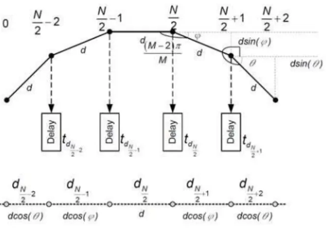
Figure A1. Sub-array antenna with even array element number.
The M elements of the cylindrical array antenna in horizontal plane are placed at the vertexes of a polygon of M sides. The separation distance between the elements is d and each internal angle is (M-2)π/M. Power dividers are used to generate N branches of the output signal from each sub-array element. Each signal can be individually combined with N-1 other signals of adjacent elements to generate a beam. When N is even, for the right half part of sub-array antenna, as shown in Figure A1, the angle 0 of
the (N/2)th array element with reference to
horizontal axis is derived as
0 (M2) 2
M M (A1)
The angle 1 of the (N/2+1)th array element with
reference to horizontal axis is derived as
1
( 2) 2
2
2 2
2 2
4
M
M M
M M
M
(A2)
Therefore, the angle i of the (N/2+i)th array
element is 2πi/M.
The separation distances among the neighboring elements for the right part sub-array are expressed as
2
_ cos
2
, , 1,..., 1 2 2
i
N
d even d i
M
N N
i N
(A3)
The time delay compensation for the right part subarray is given by
1_ 1
2 sin
2
, , 1,..., 2 2 2
i
N i
d even
n
d N
t n
c M
N N
i N
(A4)
For the left part sub-array, the angle of the (N/2-1)th
array element with reference to horizontal axis is (2π/M)×1, and the (N/2-2)th array element with
reference to horizontal axis is (2π/M)×2. The separation distances among the neighboring elements of the non-uniform linear array are
2
_ cos
2
, 1,2,..., 1 2
i
N
d even d i
M
N i
(A5)
The time delay compensation for the left part subarray is given by
_
1
2 sin
2
, 1,2,..., 1 2 i
i
d even n
d N
t n
c M
N i
(A6)
A Three‐Dimensional Position Architecture Using Digital TDE Receiver and Cylindrical Array Antenna, J. Mar et al. / 175‐182
Vol. 11, April 2013 182
Acknowledgements
The research work was supported by the research grants from National Science Council, Taiwan, R. O. C. (NSC 99-2221-E-155 -031) and CSIST.
References
[1] J. C. Liberti Jr. and T. S. Rappaport, “Smart Antennas for Wireless Communications: IS-95 and Third Generation CDMA Applications,” Prentice Hall, 1999. [2] W. H. Foy, “Position-Location Solutions by Taylor-Series Estimation,” IEEE Trans. on Aerospace and Electronic Systems, 1976.
[3] Ali Broumandan et al., “Practical Results of Hybrid AOA/TDOA Geolocation Estimation in CDMA Wireless Networks,” Proceeding of IEEE VTC’08 Fall,Calgary,Alberta,Canada, 2008.
[4] Y. Bar-Shalom et al., “Analysis of Wide-Band Cross Correlation for Time-Delay Estimation,” IEEE Trans. on Signal Processing, vol. 41. no. I, 1993.
[5] Joseph C. Hassab and Ronald E. Boucher, “Optimum Estimation of Time Delay by a Generalized Correlator,”
IEEE Trans. on Acoustics, Speech, and Signal Processing, vol. ASSF-27, no. 4, 1979.
[6] J. T. Gillis, “Computation of the Circular Error Probability Integral,” IEEE Trans. on Aerospace and Electronic Systems, vol. 27, no. 6, 1991.
[7] R. C. Johnson and H. Jasik, “Antenna engineering handbook,” 2nd Ed., McGraw-Hill, Book Co., New York, 1984.
[8] T. D. Chiueh and P. Y. Tsai, “OFDM Baseband Receiver Design for Wireless Communications,” John Wiley& Sons, 2007.