AN ANALYSIS OF INTER-BAR CURRENTS
ON A POLYPHASE CAGE INDUCTION MOTOR
Renato Carlson
1Cláudia A. da Silva
1Nelson Sadowski
1Michel Lajoie-Mazenc
21
GRUCAD/CTC/UFSC- Campus Universitário - Florianopolis - SC - 88040-900 - BRAZIL 2
LEEI/ENSEEIHT/INPT UMR CNRS 5828 - 2 rue Camichel- 31071 - Toulouse - FRANCE
ABSTRACT
This work uses a methodology based on 2D-Finite Element Method (FEM) and on the Circuits Theory (Independent Currents Method) to analyze the inter-bar currents on the rotor of cage induction motors. The Multi-Slice Technique is used to consider the skewing effect. Three conditions are considered: one inter-bar resistance, two inter-bar resistances and three inter-bar resistances. The results show the distribution of currents in the rotor bars, short-circuit rings and transversal resistances at a given time. The fundamental component of the inter-bar and surrounding bar currents are shown to help understanding the phenomenon.
KEYWORDS: induction motor, inter-bar, stray load losses, cage rotor.
RESUMO
Este trabalho usa uma metodologia baseada no Método de Elementos Finitos 2D (FEM) e na Teoria de Circuitos (Método das Correntes Independentes) para analizar as correntes inter-barras no rotor de um motor de indução com rotor de gaiola. A Técnica de Multiplas Fatias é usada para considerar o efeito da inclinação das barras do rotor. Três condições são consideradas: uma resistência inter-barra, duas resistências inter-barras e três resistências inter-barras. Os resultados mostram a distribuição das correntes nas barras do rotor, anéis de curto-circuito e resistências
transversais em dado momento de tempo. A componente fundamental da corrente nas resistências inter-barras e nas barras circundantes é mostrada para auxiliar na compreensão do fenômeno.
PALAVRAS-CHAVE: motor de indução, interbarra, perdas adicionais em carga, rotor em gaiola.
1 INTRODUCTION
Inter-bar currents have been investigated in the last few years because they are one important component of the stray load losses in cage induction motors. According to C.N. Glew (1997), even in the present day, the stray load losses are a challenge to the industrial and scientific community because there is not consensus on standard methods to measure and calculate them.
The inter-bar currents, related to the rotor bar insulation problems, produce the inter-bar losses that can represent one-third of the total stray load losses. To reduce the inter-bar losses represents to increase the efficiency of the motor and industrial experiences confirm the better performance of induction motors with insulated rotor bars.
Important contributions are found in the literature about the inter-bar currents problem. The analytical work of Odok (1958) and Rao and Butler (1969) were the main reference for several decades. Recently, Williamson and Boger (1999) have studied the effect of the inter-bar currents in a Brushless Doubly Fed Motor. The 2D and 3D-Finite Element Methods are used by Ho et al. (1998)(1999) to estimate the inter-bar losses of an induction motor.
Artigo Submetido em 08/01/04 1a. Revisão em 13/04/04;
Aceito sob recomendação do Editor Associado Prof. Dr. Prof. José Antenor Pomilio
2.1 Rotor circuit equations with inter-bar
resistance
agreement with da Silva et all (2000), for skewed motors with very low end-ring impedance, only the effective rotor bar insulation can avoid the inter-bar currents and
consequently the inter-bar losses. Transversal resistances rq are inserted between the rotor bars as shown in Fig.1 where the Finite Elements Method models the ncm rotor bars.
In this work a methodology based on the 2D-Finite Element Method and the Circuits Theory (Independent Currents Method) is used to analyze the inter-bar currents on a Polyphase Cage Induction Motor, specially the influence of the position of the transversal resistance in the rotor circuit on these currents.
By using the Circuits Theory (Independent Current Method) one tree with n edges is selected where the loops of this tree are defined as the ncm inferior ring segments, the inter-bar resistances and the last superior ring segments. The tree branches are the (ncm x nft) bar segments and the (ncm–1) superior ring segments. The tree selected is shown in Fig.1 where the heavy lines represent the branches and the thin lines represent the loops. Zr is the end ring segment
impedance and Uci,j is the voltage of each bar segment
modeled by Finite Elements. The rotor end-ring impedance and skin effect are taken into
account. The skew effects are considered by using Multi-Slice Technique (an approach to represent the skewing in two dimensions). The effect of the amature windings end turns is neglected.
Satisfying the Kirchoff’s Laws, two equations are obtained from the rotor circuit of the Fig.1. According to Boite, R. and Neirynck, J. (1996), the first equation, shown in (3) respects the relation between the loop currents and branch currents. The second one, shown in (4) respects the relation between the loop voltages and branch voltages.
2 NUMERICAL
MODEL
(da Silva et alii2000)
By using the multi-slice technique the structure is divided in nft slices and the angle difference between slices is α which is defined by the skew angle δand nft.
From the Maxwell’s equations and introducing the magnetic vector potential A and the scalar potential φ we obtain in each slice the partial differential equations given by (1) to each slice s as given in (1). The cuts in the structure are symmetrical and the length of each slice is lx.
The coefficients ν and σ are the magnetic reluctivity and the electric conductivity respectively [9].
(
)
0 0 0 = − ∂ ∂ + = − ∂ ∂ + = + + ∂ ∂ − × ∇ × ∇∫∫
∫∫
s c S s s c s c s c s b S s co x s b s b s c x s b b co s s U dS t A R I R U dS t A N l I R U l I S N t A A c b σ σ σ ν b S (1)Figure 1– Rotor circuit with selected tree Heavy lines : branches; Thin lines : loops
0
1 =
− a m
C B I
I (2)
The number of turns in series in each coil of the stator winding is Nco. The current, cross section and d.c. resistance of each slice of this coil are Ib, Sb and Rb respectively. Uc,
Rc and Sc are the voltage drop, resistance and cross section of each slice of the massive conductor.
0
1 C
+
M m+
M m=
T a
I
dt
d
L
I
R
U
B
(3)Matrix B1aT is taken from the Fundamental Mesh Matrix that is obtained directly by the number of the rotor bars and slices defined to skew the rotor.
The electromagnetic torque is calculated using the Maxwell Stress.
Vector UC and IC contains the voltage drop and currents of all rotor bar segments respectively. RM and LM are the resistance and matrix inductance associated to the tree. The inter-bar resistance rq is taken into account in the RM matrix
2.2 Coupling the equations
Equations (2) and (3) associated to the tree are coupled to the field equations of (1). The continuity of the stator current is imposed then Ib1= Ib2= ...= Ibnft. The continuity of
the rotor bar currents (Ic1= Ic2= ...= Icnft ) is also imposed
when the transversal resistance is not introduced.
The coupled equations to all slices are solved simultaneously step-by-step by using the Euler Method and can be written in the matrix form of (4). This model is solved at first to give an initial estimated value of A(0),
IB(0), UC (0), IC (0), Im(0) and after the system of large equations is solved at each time using the result of last step. The vector UB is the source vector.
The inter-bar currents are taken directly from the vector Im defined as the vector that contains all inferior ring segments currents, the inter-bar currents and the last superior ring segment current.
By this way if one or more inter-bar resistances are inserted in the rotor circuit it is possible to know the current associated to it and to verify its influence in the others parameters of the machine.
(4) + ∆ ∆ ∆ ∆ ∆ = 0 0 0 ) ( 0 t) -(t t) -(t t) -(t t) -(t I t) -(t A 0 0 0 0 0 M 0 0 0 0 0 0 0 0 M 0 0 0 M M 0 0 0 0 M (t) (t) (t) (t) I (t) A M M 0 0 0 M 0 M 0 0 0 M M 0 M 0 0 0 M M 0 0 M M M B 17 16 15 14 13 B 12 11 10 9 8 7 6 5 4 3 2 1 t U I I U I I U B m C C m C C
3 MODEL
VALIDATION
The developed numerical model is applied to analyze a three phase induction motor rated 1000 kW, 8 poles, 60 Hz, 6000 Volts with skewed and non skewed rotor slots. This motor has 18 slots per pole in the stator and 22 slots per pole in the rotor. The skewing angle of the rotor slots in the skewed motor is about 1/4 stator slot pitch.
Figure 2 shows a picture of the skewed rotor where the effect of inter-bar currents is observed close to the ventilation holes. A closer view of the rotor is shown in Fig. 3 where the damage due to the inter-bars currents is more pronounced.
In order to validate the numerical model, the only available experimental data corresponds to the rated armature
currents. For the non-skewed motor the measured rms value of the armature current was 117.34A while the corresponding value obtained by simulation at rated slip was 117.24A. For the skewed motor the measured rms value of the armature current was 120.5A while the corresponding value obtained by simulation at rated slip was 118A. The good agreement between measured and simulated values allows validating the numerical model. The results presented in the next sections of the paper were obtained resolving the above finite elements model until the rotor quantities attain the steady-state. In order to make the calculation time reasonable enough for obtaining all the results we needed, we decided to make all the following calculations for a slip of about 10% and not for the nominal one. This fact does not invalidate the results and conclusions. Each finite elements resolution of this model for this slip took about 6 hours in a Pentium 4 1.0 GHz PC microcomputer.
Figure 2 – Skewed rotor view.
Figure 3 – Rotor view with damaged area.
Figure 4 – Flux lines over one pole pair of the motor.
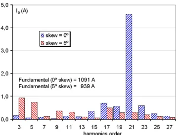
Figure 6 – Harmonics of the armature current with and without skewing.
4
THE EFFECT OF SKEWING THE
ROTOR BARS
5
ANALYSIS OF THE INTER-BAR
CURRENTS
The first simulation results present a comparison of the current waveform and harmonic content of the armature current for the non-skewed rotor as well as for the skewed rotor. For this last case the rotor bars were considered skewed 5 mechanical degrees, which correspond to one stator slot pitch and not only 1.25 mechanical degrees as it is in the real motor. This was done in order to put into evidence the effect of skewing the rotor bars.
It is almost impossible to obtain experimentally the value of the inter-bar resistances because their magnitudes are very low, in the order of the measuring instruments precision. Due to this an arbitrary value of 40 µΩ was adopted.
To study the inter-bar currents in the rotor of a skewed induction motor 4 slices where adopted to represent the skewing. The numerical model presented in section 2 permits to represent any number of inter-bar resistances. Fig. 7 show the grid formed by the bar segments and the inter-bar resistances inserted and the notation used hereafter to designate the inter-bar resistances and the bar segments. Fig. 5 and Fig. 6 show the effect of skewing over the
armature current. In particular, its effect is mostly apparent over the 21st harmonic which corresponds to the main rotor slot harmonic. It is important to observe that this motor has by its design a low level of slot harmonics, for that reason it was designed originally with the rotor bars skewed ¼ of the stator slot pitch.
The analytical work of Odok, A. (1958) shows that if the end-ring impedance is negligible, the bar current of a
non-Figure 7 – Grid formed by the bar segments and the inter-bar resistances inserted and the respective notation. Figure 5 – Armature current with no skew and
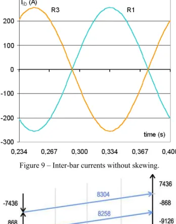
skewed motor is constant over the length of the bar and there are no inter-bar currents flowing in the rotor circuit, even if there are transversal resistances between bars. A simulation without skewing the rotor but considering the three inter-bar resistances of Fig. 7 permits to verify this condition. For the simulation the resistance of the ring segments between two bars was 1 µΩ low enough but not negligible. Fig. 8 shows the current distribution in the rotor for a given instant of time.
Figure 8 – Current distribution in the rotor grid at a given time with three transversal resistances and no skew. A small amount of inter-bar current is flowing through R1 and R3. The path of this current is indicated in Fig. 8 by the dotted line. The rotor is symmetric in the axial direction as can be seen in this figure and that is why the current in R2 is zero. Fig. 9 shows the inter-bar currents as a function of time.
Three cases where studied next with the rotor bars skewed 5º. The first one with only one transversal resistance inserted and designated as R1 in Fig. 7. The second one with two resistances inserted and designated as R1 and R2. The last one considered three resistances inserted and designated as R1, R2 and R3.
Initially, the distribution of the currents at a given instant of time over the portion of the rotor grid presented in Fig. 7 without any inter-bar resistance is shown in Fig. 10. The values of current shown in this figure will serve as a reference for the three cases to be analyzed.
5.1 One inter-bar resistance (R1)
Fig. 11 shows a portion of the rotor grid for the case where there is only one inter-bar resistance. The arrows indicate the direction of the currents at a given instant of time in the bar segments, in the ring segments and in the transversal resistance R1. The path of the current due to the presence of the inter-bar resistance is indicated in this figure by a dashed line and show that the inter-bar current flows from
one bar segment to the next one in the direction of the rotor bar skewing.
Figure 9 – Inter-bar currents without skewing.
Figure 10 – Current distribution in the rotor grid at a given time without any transversal resistance.
The fundamental components of the currents in the bar segments surrounding the transversal resistance are shown in Fig. 12. The amplitude of the fundamental component of the inter-bar current is, in this case, 2822 A. This figure shows that only the bar segments A and B currents are affected by the presence of the inter-bar resistance R1. Also, the current in bar segment A is increased by the amount of inter-bar current while the current in segment E is decreased of the same amount confirming the previous conclusion.
These figures show that the main harmonic of the inter-bar current corresponds to the stator main slot harmonic, i.e. the 19th. It is interesting to note that the predominant harmonic in the armature current is the 21st that corresponds to the rotor slot harmonic. The amplitude of the 19th harmonic of the inter-bar current corresponds to 2.25% of the amplitude of its fundamental. Besides the fundamental component and the 21st harmonic there is also a significant ninth harmonic of about 30 A peak value. This ninth harmonic corresponds to the 60 Hz frequency of the armature currents. All other harmonics are not significant.
5.2 Two inter-bar resistances (R1 and
R2)
Fig. 15 shows the same portion of the rotor grid as in Fig. 11, but this time for the case where there are two inter-bar resistances. The arrows indicate the direction of the currents at a given instant of time in the bar segments, in the ring segments and in the transversal resistances R1 and R2. The path of the currents due to the presence of the inter-bar resistances are indicated in this figure by two dashed lines that show the same effect of displacement of the currents in the direction of the rotor bar skewing.
Figure 12 – Amplitude of the fundamental component of the bar currents surrounding inter-bar resistance R1
(refer to Fig. 7 for notation).
The waveform of the inter-bar current flowing through resistance R1 is shown in Fig. 13 and its harmonic spectrum is shown in Fig. 14.
Figure 14 – Fourier series decomposition of the current flowing through the inter-bar resistance R1.
Figure 15 – Current distribution in the rotor grid at a given time with two transversal resistances.
The fundamental components of the currents in the bar segments surrounding the transversal resistances are shown in Fig. 16. The amplitude of the fundamental component of the inter-bar currents is, in this case, 1801 A in R1 and 2288 A in R2. This figure shows now that the current in bar segments A, B, E and F currents are affected by the presence of the inter-bar resistances R1 and R2. Also, the currents in bar segments A and B are increased while the currents in segments E and F are decreased confirming the previous conclusion.
Figure 16 – Amplitude of the fundamental component of the bar currents surrounding inter-bar resistances R1 and
R2 (refer to Fig. 7 for notation).
5.3 Three inter-bar resistances (R1, R2
and R3)
Fig. 17 shows the same portion of the rotor grid as in Fig. 11 and Fig. 15, but this time for the case where there are three inter-bar resistances. The arrows indicate the
direction of the currents at a given instant of time in the bar segments, in the ring segments and in the transversal resistances R1, R2 and R3. The path of the currents due to the presence of the inter-bar resistances are not indicated in this figure but the same effect of displacement of the currents in the direction of the rotor bar skewing is observed.
Figure 17 – Current distribution in the rotor grid at a given time with two transversal resistances.
The fundamental components of the currents in the bar segments surrounding the three transversal resistances is shown in Fig. 18. This figure shows now that the current in all bar segments surrounding the inter-bar resistances are affected by their presence. The currents in bar segments E and D are visibly decreased while the currents in bar segments A, B, G and H are increased confirming the previous conclusion.
The overall view of the amplitudes of the fundamental of the inter-bar currents in the cases discussed above is presented in Fig. 19.
It is observed that for only one transversal resistance inserted between rotor bars the amplitude of the fundamental of the inter-bar current is about 2822 A and is higher than the corresponding current on the same resistance when two (1801 A) or three (1673 A) resistances are inserted. Another observation is that the amplitude of the fundamental component of the inter-bar currents over the two or three resistances cases is not constant. In fact, the amplitude of the inter-bar current is higher for the resistance closer to the middle of the rotor.
Figure 18 – Amplitude of the fundamental component of the bar currents surrounding inter-bar resistances R1,
R2 and R3(refer to Fig. 7 for notation).
Figure 19 – Amplitude of the fundamental of the inter-bar currents (refer to Fig. 4 for notation)
Figure 20 – Waveform of the torque.
Figure 21 – Decomposition of the torque into a Fourier series.
no inter-bar resistance : 31,204 Nm 1 inter-bar resistance : 31,263 Nm 2 inter-bar resistances : 31,279 Nm 3 inter-bar resistances : 31,281 Nm The Fourier series decomposition of the torque waveforms
of Fig. 20 is shown in Fig. 21. These differences may be attributed to numerical errors. The harmonic decomposition of the torque curves in Fig. 21
shows a 60 Hz first harmonic and both the stator and rotor slot harmonics, respectively the 17th and 19th and the 21st and 23rd. The effect of the existence of inter-bar currents acts differently over the harmonics of torque. Over the first harmonic this effect is significant, reducing its amplitude. Over the continuous component of torque their effect is not perceptible, its calculated value varies as follows:
6 CONCLUSION
The main goal of this work was to contribute for the understanding of the phenomenon of inter-bar currents in the rotor of squirrel-cage induction motors.
The results presented confirm the theoretical results of Odok (1958) concerning the fact that inter-bar currents can circulate in the rotor if there are inter-bar low resistance paths even when the rotor is not skewed conditioned to having non zero ring impedance.
The analysis of three cases with one, two and three inter-bar resistances showed that the skewing makes the rotor asymmetrical in the axial direction. This fact makes the inter-bar currents circulation path be ‘displaced’ in the direction of the skew. Comparing the figures of rotor currents distribution at a given time without skew and with skew evidences this conclusion. Another important conclusion concerns the motor torque which continuous component is very slightly influenced by the presence of the inter-bar currents. These currents affect only its harmonic components mainly the first one that corresponds to the 60 Hz mains frequency.
6.1 ACKNOWLEDGEMENT
This research was supported in part by WEG Industries from Jaragua do Sul, Brazil.
References
Glew, C.N. (1997). Stray Load Losses in Induction Motors: A Challenge to Academia. Proc. of the 8th IEE Intl.
Cont. on Electrical Machines and Drives,
Cambridge, England, pp. 180 -184.
Odok, A. (1958). Stray Load Losses and Stray Torques in Induction Machines. Trans. AIEE, Vol. 77, nº 4, pp. 43-53.
Rao, V.S. and Butler, O.I. (1969). Stray Load Losses of Polyphase Cage Induction Motors with particular reference to the condition of imperfect rotor-bar-iron insulation. Proc. of the IEE, Vol. 116, nº. 5, pp. 737-751.
Williamson, S. and Boger, S. (1999). Impact of Inter-Bar Currents on the Performance of the Brushless Doubly Fed Motor. IEEE Trans. Ind. Applicat., Vol. 35, nº 2, pp. 453–460.
Ho, S.L., Fu, W.N. and Wong, H.C. (1998). Estimation of Stray Losses of Skewed Rotor Induction Motors Using Coupled 2-D and 3-D Time Stepping Finite Element Methods, IEEE Trans. on Magn., Vol. 34, nº 5, Part 1, pp. 3102 - 3105.
Ho, S.L., Li, H.L. and Fu, W.N. (1999). Inclusion of Inter-bar Currents in a Network-Field Coupled Time-Stepping Finite-Element Model of Skewed Rotor Induction Motor. IEEE Trans. Magn., vol. 35, pp. 4218–4225.
Boite, R. and Neirynck, J. (1996). Théorie des Réseaux de Kirchhoff - Traité d’Electricité,328 pages, Vol. IV, Presses Polytechniques Romandes, Lausanne, Switzerland.
da Silva, C.A., Carlson, R., Sadowski, N., Lefevre, Y. and Lajoie-Mazenc, M. (2000). A New Method to Calculate the Inter-bar Currents in Induction Motors – Part I –Methodology, Proc. of the 9th International IGTE Symposium on Numerical Field
Calculation in Electrical Engineering - IGTE 2000,
Graz, Austria, pp. 436–439.
da Silva, C.A., Carlson, R., Sadowski, N., Lefevre, Y. and Lajoie-Mazenc, M. (2000). A New Method to Calculate the Inter-bar Currents in Induction Motors – Part II – Results : The Skewing Effect , Proc. of the 9th International IGTE Symposium on Numerical Field Calculation in Electrical
Engineering - IGTE 2000, Graz, Austria, pp. 245–