Procedure for decreasing the required time for ire
resistance of the multistory buildings
Procedimento para redução do tempo requerido de
resistência ao fogo de edifícios de múltiplos andares
Abstract
Resumo
The Brazilian standard ABNT NBR 15200: 2012 details a procedure for decreasing the required time of ire resistance in buildings with good ire safety characteristics. It called equivalent time method. This name can confuse the less habituated to the ire safety area, because the Brazilian procedure is not equal to the original equivalent time method, European. The purpose of this paper is to discuss the equivalent time method, to detail the origins of the Brazilian method and present their limitations no explicit in the Brazilian standard. Some unknown aspects of most re -searchers or technical means are presented. It should be highlighted the abundant bibliography presented to aid the understanding of a seemingly simple issue, but it incorporates many concepts of ire safety, not always understood by the users.
Keywords: ire, ire resistance, equivalente time method, decresing ire resistance required.
A ABNT NBR 15200:2012 detalha um procedimento para a redução do tempo requerido de resistência ao fogo de ediicações com boas caracte -rísticas de segurança contra incêndio. Ele recebe o nome de método do tempo equivalente. Esse nome pode confundir os menos afeitos à área de segurança contra incêndio, pois o procedimento brasileiro não é equivalente ao MTE original, europeu. O objetivo deste artigo é discorrer sobre o MTE, detalhar as origens do método brasileiro e apresentar suas limitações não explícitas na norma brasileira. Apresentam-se alguns aspectos desconhecidos da maioria dos pesquisadores ou do meio técnico. Destaca-se a revisão bibliográica apresentada ao longo do texto, para auxiliar a compreensão de um tema aparentemente simples, porém que incorpora diversos conceitos sobre segurança contra incêndio, nem sempre compreendidos pelos usuários.
Palavras-chave: incêndio, TRRF, resistência ao fogo, método do tempo equivalente.
a Escola Politécnica da Universidade de São Paulo, São Paulo, SP, Brasil; b Universidade Estadual de Campinas, Campinas, SP, Brasil.
Received: 20 May 2016 • Accepted: 16 Jan 2017 • Available Online: 04 Oct 2017
V. P. SILVA a [email protected]
C. N. COSTA b [email protected]
1. Introdução
For more than 8 decades, many researchers have attempted to re-late the temperature-time curve of a ire, standardized by various international standards (ASTM E119, 2000; ISO 834, 1990; BS 476, 1987) with more realistic curves. More information about the stan -dard-ire (ISO-ire) can be seen in Silva (2012) and Silva (2014). The EC1 (2002) included the equivalent time method associated with the concept of value of the ire load design, based on the German standard DIN (1987). The Eurocode allows each country to make changes in the method in their local regulations. For ex-ample, the UK and Portugal did it.
In Brazil, in the 90s, the Fire Department of Sao Paulo State in-cluded in its Technical Instruction (in this text we will simplify by IT) the equivalent time method with several modiications. This IT was published in 2001. In view of the changes, we could not call it of equivalent time method because it could cause confusion to the reader, imagining it to be identical to the method published by the Eurocode. However, by Brazilian tradition is still so called. This is the case of NBR 15200:2012 that use this name.
The aim of this paper is to present the state of the art of the equiva-lent time method, detailing its formulation and the procedure for reduction the required time for ire resistance that, despite being inspired by the equivalent time method, it had the contribution of other foreign standards and has undergone several modiications.
2. The equivalent time method
2.1 Historic
In 1928, Ingberg apud HARMATHY (1987) conducted a series
of tests at NIST - National Institute of Standards and Technology (then called United States National Bureau of Standards), com-paring the areas under actual ire curves with the area under the standard curve, from a predetermined limit temperature (NYMAN, 2002), as shown in Figure 1. He admitted that this area was pro -portional to the thermal energy given off by the hot gases. The results are shown in Table 1 and Figure 2.
Equation 1 is an adequate approximation to less than 180 min time (Costa, 2008), where qw is the value of ire load density expressed in kg of equivalent wood per unit area.
(1)
This concept is interesting since the severity of the ire is inde-pendent of the structure to be analyzed. That is, two ires with the same severity lead to the same results regardless of the structural element studied.The Japoneses KAWAGOE; SEKINE (1964) apud (LAW, 1997) fol-lowed the same idea from Ingberg, comparing the areas under the curves, but have identiied the importance of ventilation (oxygen is the oxidizing material) to determine the temperature of the hot
Figure 1
Time equivalent by the concept of the equality
of areas under the curves
Source: Melão (2016)
Figure 2
Relationship between the ire load and time
as Ingberg
Table 1
Relationship between the ire load and time
as Ingberg (GEWAIN et al., 2003)
qw (kg of wood/m²) te (min)
24.4 30
36.6 45
48.8 60
73.2 90
97.6 120
146.5 180
195.3 270
244.1 360
gases in the compartment (see item 4 from this text) presenting Equation 2, valid within certain limits of
A / A . h
t v m.In Equation 2, k1 is a factor of proportionality, qi is the speciic ire load per loor area, At is the area of all surfaces (loor, ceiling and walls) of the ire compartment and hm is the average height of the openings to the outside of the compartment where oxygen enters.
(2)
COOPER, STECKLER (1996) and THOMAS et al. (1997) do not agree with the equivalence between areas, saying they do not repre -sent the thermal energy given off by hot gases, however, we deemed important to mention this concept, as it was a starting point for current ire safety regulations. In MELÃO (2016) a simulation was performed using the equivalent areas, which did not lead to good results. Law and Petterson apud THOMAS et al. (1997) indicate that the best way to determine the equivalent time is a comparison be-tween the temperatures of structural elements calculated as the two curves as illustrated in Figure 3.In Figure 3, the “structural element” may be a rebar of concrete element or a steel proile, for example.
In 1971, the British researcher Margaret Law examined the re -lationship between the standard curve and experimental curves, including the effect of ventilation, but based on Figure 2, and pro-posed the Equation 3 to determine the equivalent time (HARMA-THY, 1987).
(3)
In Equation 3, k2 is a factor of proportionality, Av is the area of the openings to the outside of the compartment and Af is the compart-ment loor area.
The Swedish researcher Pettersson included in 1973, the thermal characteristics of the compartmentation element (see item 4 of this text), in determining the equivalent time (HARMATHY, 1987). Pet-tersson used natural ire curves theoretically deduced with experi -mental admeasurements (PETTERSSON et al., 1976) to propose Equation 3.
In Equation 3, k3 is a factor of proportionality and K1 is a factor related to the physical and thermal characteristics of the compart-mentation elements.
(3)
The German standard DIN (1987) includes the inluence of the horizontal openings in the ventilation and the level of ire risk, as Equation 4.
(4)
In Equation 4, K2 is a factor related to the physical and thermal characteristics of the compartmentation elements, W1 is a fac-tor related to the horizontal or vertical ventilation, determined by means of tables provided by DIN (1987) and γ is a factor related to the risk.Reminding that risk is the association between hazard and conse -quences of a ire, the factor γ, introduced by DIN (1987), is deter -mined taking into account the dimensions of the building and the presence of active protection. The next version of the DIN, DIN (1998), made some minor modiications (CAJOT et al.) to deter-mine the equivalent time.
The method disclosed in DIN, with adaptations that facilitate its use (e.g., the ventilation effect, determined by tables has been trans-formed into an equation in EC1) was adopted in EC1 (1995), using Equation 5.
Figure 3
Concept of equivalent time
(5)
In Equation 5, K2 is a factor related to the physical and thermal characteristics of compartmentation elements, W is related to the ventilation (which depends on the size of the openings) and qi,d,the design value of the ire load.
It should be noted in equation recommended by the EC1 (1995), the introduce of the design value of the ire load, qi,d, which is the characteristic value of the ire load determined by measure-ments or standard tables, multiplied for several factors γ. In EC1 (1995), the only factor presented explicitly was 0.6 when there was sprinklers.
In this part of history, should be cited the publication SCHLIECH; CAJOT (1997). Firstly, because both were the coordinators of the part of the ire of the EC1 and then because Schleich anticipated to SILVA (1997), the main results would be published. It was ex-pected, therefore, that the review of EC1 (1995) follow SCHLEICH; CAJOT (1997).
SCHLEICH; CAJOT (1997) continued the research looking for better explain the factor γ and proposed (SILVA, 1997 and SILVA, 2004) that γ were the result of the product γ n´ γs1 ´ γ s2. γn e γs2 will be discussed later in this paper. In this item of the text the interest is on γs1.
γs1 is a factor that depends on the consequences of a collapse
Table 2
Values of
γ
s1(SCHLIECH; CAJOT, 1997)
Compartment area (m2)
Height of the building (h)
1 loor 2 loors 2 to 10 loors More than 10 loors
≤ 750 1.00 1.10 1.25 1.50
≤ 2500 1.00 1.25 1.50 2.00
≤ 5000 1.05 1.40 1.75 2.50
≤ 10000 1.10 1.50 -
-≤ 20000 1.20 1.60 -
-Table 3
Values of
γ
s1(IT 8, 2001)
Compartment area (m2)
Height of the building (h)
One story building h ≤ 12 m 12 m < h ≤ 23 m h > 23 m
≤ 750 1.00 1.00 1.25 1.50
≤ 2500 1.00 1.30 1.50 2.00
≤ 5000 1.05 1.45 1.75 2.50
≤ 10000 1.10 1.55 -
-≤ 20000 1.20 1.65 -
-Table 4
Values of
γ
s1( IT 8, 2004)
Compartment area (m2)
Height of the building (m) One story
building h ≤ 6 6 < h ≤ 12 12 < h ≤ 23 23 < h ≤ 30 30 < h ≤ 80 h > 80
≤ 750 1.00 1.00 1.10 1.20 1.25 1.45 1.60
≤ 1000 1.05 1.10 1.15 1.25 1.35 1.65 1.85
≤ 2500 1.10 1.25 1.40 1.70 1.85 2.60 3.00
≤ 5000 1.15 1.45 1.75 2.35 2.65 3.00 3.00
≤ 7500 1.25 1.70 2.15 3.00 3.00 3.00 3.00
≤ 10000 1.30 1.90 2.50 3.00 3.00 3.00 3.00
≤ 20000 1.60 2.80 3.00 3.00 3.00 3.00 3.00
(EC1, 1995), according SCHLEICH; CAJOT (1997) must comply with Table 2.
As already mentioned, the Fire Department of São Paulo included the equivalent time method in Technical Instruction n# 8 of 2001, based on EC1 (1995) updating the procedure based on SCHLEICH; CAJOT (1997). The irst author of this work made this suggestion to the CB. Two aspects should be highlighted. The irst is that the Fire Department decided to employ the equivalent time method, however, imposed a maximum reduction of 30 min in the required time for ire resistance rec-ommended by Technical Instruction n# 8 and, the other, is that the Fire Department use the Table 2 proposed by SCHLIECH; CAJOT (1997), but transformed it in the Table 3 (VARGAS, SILVA, 2005).
The alteration of some values and exchange the number of loors to height in meters did not cause large modiication in results, however, it is noted that the line corresponding to time instead of absolute values, was included the symbol “£” meaning that is not allowed interpolation and, as a consequence, depending on the level that is the compartment, there will be jumps in the results, making them unrealistically. This was solved later with the change of the factor gs1 from table to Equation 12.
SCHLIECH; CAJOT (1997) also reported that Equation 5 had good results for concrete and steel coated, but not for steel without ire protection. Prestressed concrete, wood and masonry were not mentioned in this publication.
2.1 The equivalent time method based on EC1 (2002)
After SCHLEICH; CAJOT (1997), these authors researched more about the subject and EC1 (2002) was not published exactly as de-scribed in SCHLEICH; CAJOT (1997). The Equation 5 was trans-formed in Equation 6.
(6)
In Equation 6, K is a factor related to physical and thermal char-acteristics of compartmentation elements, as shown in Table 5, W is a factor related to the ventilation and the height of the compart-ment, as Equation 7, M is a correction factor that depends on the structural material, as shown in Table 6, qi,d is the design value of the ire load per loor area (MJ/m2) determined according to
Equa-tion 8.
(7)
Equation 7 has the following limits of validity: W ≥ 0.5; 0,025 ≤Av / Af ≤ 0.25 and 12,5 [1+10 (Av ⁄ Af )] ≥ 10.
In Table 6 , t v
A
V
h .
A
=
(8)
In Equation 8, γn is determined by Equation 9 and the values of γ s1 e γs2, respectively, are determined by Tables 7 and 8.Perhaps the most important change in EC1 (2002) was the exclu -sion of building height increasing the risk of ire, assuming there -fore unrestricted reliability in vertical compartmentation.
(9)
Table 5
Values of K in function of the compartmentation
element thermal inertia (EC1, 2002)
l r ××
= c
b
(J/m².s1/2.ºC) K (min.m²/MJ)
b > 2500 0.040
720 ≤ b ≤ 2500 0.055
b < 720 0.070
Table 6
Values of “M” in function of the structural material
(EC1, 2002)
Material da estrutura M
Reinforced concrete 1,0 Steel without ire protecion 1,0
Steel with ire protection 13,7 x V Composite structures,
wood, structural masonry Not applied
Table 7
Values of
γ
s1in function of the compartment area
(EC1, 2002)
Table 8
Values of
γ
s2in function of the risk of ativation
(EC1, 2002)
Compartment area (m2) γ
s1
25 1.10
250 1.50
2500 1.90
5000 2.00
10000 2.13
γs2 Examples of ocupation
0,78 Galeria de arte, parque aquático, museu. 1,0 Escritório, residência, hotel, indústria de papel 1,22 Indústria de máquinas e motores 1,44 Laboratório químico, oicina de pintura
In Equation 9, γni are factors related to safety measures against ire as shown in Table 9.
For characteristic value of the ire load density the EC1 (1995) rec-ommends the Table 10.
3. Brazilian procedure to reduce
the required time for ire resistance
LAW (1997) concludes that the methods of equivalent time pre-sented so far, and even the Eurocode, are not satisfactory and need to be further evaluated.
The Eurocode allows each country to adapt the national standard to their reality. For example, in the case of the equivalent time method, the Portuguese and British versions of the EC1 have dif-ferent forms of the equivalent time method. In the Portuguese ver-sion (EUROCÓDIGO 1, 2010), gn ´ gs1 ´ gs2 = 1. The version of
Eurocode 1 published in UK, BS (2007), extends the use of the method of time equivalent to all structural materials and includes the height of the building in risk analysis, among other details. In Brazil, ABNT NBR 15200:2012, ABNT NBR 14323:2013 and technical instructions of the Fire Department from sever-al states, present a procedure to reduce the required time for ire resistance in buildings with good features of ire safety. Al-though it is called of equivalent time method, it is not the original method from Eurocode, but a procedure that takes advantage of the formulation presented in several international standards and publications.
Remembering that the Technical Instruction CB-02-33 of 1994 allowed reducing in 30 minutes the required time for ire resis-tance to buildings with sprinklers, the new procedure was a ma-jor breakthrough. On one hand, the sprinklers may not be suf-icient to ensure safety, on the other, buildings without sprinklers may be safe. With this objective,in 2001, the IT 8 of the Fire De-partment of Sao Paulo State included the method of equivalent time with several modiications from the original one. The NBR 15200:2012 and NBR 14323:2013 included in their texts that procedure, still calling of equivalent time method.
Now we will detail the procedure recommended by ABNT NBR 15200: 2012.
The required time for ire resistance of structural elements of reinforced concrete in each compartment can be determined by Equation 10, but cannot be reduced more than 30 min from the required time for ire resistance given in Table A.1 of ABNT NBR 14432: 2001 or those required by the technical instructions of the Fire Department.
(10)
In Equation 10, the value 0.07 is the maximum value of K factor re-lated to physical and thermal characteristics of the compartmenta-tion elements shown in Table 5. The value of qi,k can be determined by local measurements or use standardized values as ABNT NBR 14432:2001 or technical instructions of the Fire Department. SomeTable 9
Fatores de ponderação das medidas de segurança contra incêndio (EC1, 2002)
γn1 γn2 γn3 γn4 γn5
Chuveiros automáticos
Detecção automática
Existe
Suprimentos de água independentes
0 1 2 Calor Fumaça Transmissão automática
0,61 (*) 1,0 0,87 0,7 0,87 (*) 0,73 (*) 0,87 (*)
γn6 γn7 γn8 γn9 γn10 γn11
Brigada contra incêndio Rotas de fuga (existe e é desobstruída)
Escada pressurizada
Exaustão de fumaça nas
escadas
Dispositivos de combate Interna Externa
0,61 (*) 0,78 (*) Não –1,5Sim – 1,0 Sim – 0,9 (*) Sim – 1,0Não –1,5 Não –1,5Sim – 1,0
(*) na ausência, γni = 1,0
Table 10
Carga de incêndio especíica em MJ/m
2(EC1, 2002)
Ocupação Média 80% fráctil*
Residência 780 948
Hospital (quarto) 230 280
Hotel (quarto) 310 377
Biblioteca 1500 1824
Escritório 420 511
Escola (sala de aula) 285 347
Shopping Center 600 730
Teatro/cinema 300 365
Área de embarque 100 122
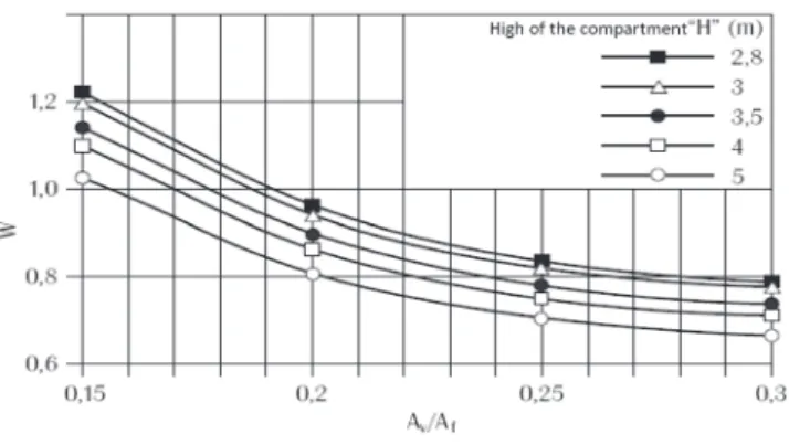
values are shown in Table 11. W follows the same Equation 7, dis -regarding horizontal openings, hence , Equation 11.
(11)
With the limit 0,025 ≤ Av/Af ≤ 0,30.
The upper limit of Av / Af was increased in the Brazilian standard in view the graph shown in Figure 4.
Table 11 from of IT 14 (2011) is based on the ABNT NBR 14432:2001,
Table 11
Valores de cargas de incêndio especíicas (IT14, 2011)
Ocupação/uso Descrição Filler
Residencial Apartamentos, casas térreas, sobrados, pensionatos 300
Serviços de hospedagem Hotéis, motéis, apart-hotéis 500
Comercial varejista
Automóveis 200
Drogarias 1000
Livrarias 1000
Lojas de departamentos (shopings) 800
Papelarias 700
Supermercados (vendas) 600
Tapetes 800
Serviços proissionais, pessoais e técnicos
Agências bancárias 300
Agências de correios 400
Escritórios 700
Oicinas elétricas 600
Oicinas mecânicas 200
Educacional e cultura física
Academias 300
Creches 300
Escolas em geral 300
Locais de reunião pública
Bibliotecas 2000
Cinemas ou teatros 600
Clubes sociais, boates 600
Estações, terminais de passag. 200
Igrejas 200
Museus 300
Restaurantes 300
Serviços automotivos Estacionamentos 200
Oicinas 300
Serviços de saúde e institucionais
Asilos 350
Clínicas e consultórios médicos ou odontológicos 300
Hospitais 300
Presídios 200
Quartéis 450
Ver Table completa na IT 14 (2011)
Figure 4
Values of H in function of the ventilation A
v/A
fand compartment height H
which in turn followed the Austrian standards TRVB A-100 (1987) and TRVB A-126 (1987). These Austrian standards were based on Gretener method (SIA, 1996).
The factor γn is determined by Equation 9, but in a simpliied way, as can be seen in Table 12. In the absence of any means of protec-tion, indicated in Table 12, adopt γn equal to 1.
The factor γs1 is determined by Equation 12, where Af is the loor area of the compartment in square meters, and h is the distance between the highest habitable loor and the lowest (either under -ground) of the building in meters. For gS1 <1, it should be adopted gs1 = 1 and gs1> 3, can adopt gs1 = 3.
Given that the inal version of EC1 (2002) the inluence of height had been removed from the equivalent time method and the tables recommended in IT8 (2001 and 2004) had unwanted and unreal-istic discontinuities, Equation 12 was created based on the follow-ing principles: maintain the inluence of the height; slightly reduce the inluence of height, do not to differ much from the results ob-tained with the method recommended by IT8 (2001, 2004) that was based on proposals from the Eurocode review; adopt a limit value slightly higher than the previous, 2.5; don´t have discontinui-ties and be easy to use. Although there are some differences in the results obtained by Equation 12 and tables of IT 8, the inal values of the required time for ire resistance of buildings are very similar as shown in SILVA (2008).
(12)
The gs2 factor has the same function as that recommended by EC1 (2002), i.e., consider the risk of ire activation. According SCHLEICH; CAJOT (1997), the factor gs2 means the hazard of
ire activation and was originated in Gretener method for analysis of ire risk in buildings, published in the SIA-81 (1996). The EC1 (2002) does not provide suficient examples of buildings. Then Table 9 was completed based on Gretener method (SIA 81, 1996), generating the Table 13.
Tables 11 and 13 originated in Gretener method. In 1960, Max Gretener engineer, director of Fire Protection Association, Switzer-land, began studies on calculating the risk of ire in industries and large buildings. Their method, published in 1965, aimed to meet the needs of insurance companies. In 1968 the Swiss Fire De-partment proposed to adopt the same method also to assess the means of ire protection of buildings. In 1984, SIA (Société Suisse des Ingénieurs et des Architectes) published the SIA-81 document “Method of assessment of ire risk,” based on the Gretener work and reviewed by a group of experts from private and state insur -ance companies and SIA. This group has adapted the method to the then knowledge and Swiss and international experience. In De-cember of 1996, SIA-81 was revised and updated, SIA 81 (1996). According Cajot et al. (no date) the results of this work are scien-tiically demonstrable, although not all have been demonstrated. In addition to the limitations already mentioned, to safety side, also was imposed that time determined by the method presented can not be less than 15 min and qi,k γn γs ≥ 300 MJ/m2
..
4. Compartimentation
It notes that the procedure described in item 3 of this text is to be used for each compartment. So, the concept of compartment must be very clear to the user.
Compartment is the building or part thereof, comprising one or more rooms, spaces or loors, built to prevent the spread of ire from inside to outside of the boundaries, including the spread be-tween adjacent buildings, where applicable. Compartmentation elements are constructive elements which seal the compartment and must have thermal insulation, integrity and structural stability. The horizontal compartmentation is that which prevents the hori-zontal spread between compartments on the same loor. It limits the spread of ire, restricting the losses and facilitating the activity of ire ighting. The IT9 (2011) limits the maximum areas for enclo-sures (horizontal compartmentation), depending on the use and height of the building
The vertical compartmentation is that which prevents the vertical spread of gases or heat to a loor immediately above. It is one of
Table 12
Fator de ponderação
γ
ndas medidas
de segurança contra incêndio
(ABNT NBR 15200:2012; IT8, 2011)
Valores de γn1, γn2 e γn3
Existência de chuveiros automáticos
γn1
Brigada contra incêndio
γn2
Existência de detecção
automática γn3
0,60 0,90 0,9
Table 13
Valores de
γ
s2em função do risco (r) de ativação do incêndio (ABNT NBR 15200:2012; IT8, 2011)
γs2 r Exemplos de ocupação
0,85 Pequena Escola, galeria de arte, parque aquático, igreja, museu
1,0 Normal
Biblioteca, cinema, correio, consultório médico, escritório, farmácia, frigoríico, hotel, livraria, hospital, laboratório fotográico, indústria de papel, oicina elétrica ou mecânica, residência, restaurante, supermercado, teatro, depósitos (produtos farmacêuticos, bebidas
alcoólicas, venda de acessórios de automóveis) e depósitos em geral 1,2 Média Montagem de automóveis, hangar, indústria mecânica
the most effective measures for ire safety. It is also essential for the calculation of structures in ire.
The vertical compartmentation includes: facade with beam-parapet or marquise, emergency stairs enclosure, slabs with a minimum thickness in order to respect insulation and integrity and sealant (irestops) to seal any vertical connection between loors, such as passage pipes, ducts, shafts etc.
As the law of the São Paulo (SP 2011), the vertical compartmenta-tion is required for residential buildings, ofices or hotels and other occupations, for ire heights exceeding 12 m, except for hospitals where the minimum height is 6 m. Further details and requirements for compartmentalization can be seen in the technical instructions of the ire departments or SILVA (2014).
Another important aspect is the distance between facades. This distance must be calculated in such a way as to prevent the pas -sage by radiation from a possible ire of a facade to another in another building, or of the same building (NFPA, 2012; IT7, 2011; SILVA, 2012; SILVA, 2014 ). If this distance is less, the compart-ment will be extended to another building or another loor of the same building.
In short, to correctly apply the procedure reducing the required time for ire resistance must be checked several aspects of archi -tecture and not only apply Equation 10.
5. Partial factors
When using a method of risk assessment, analyzing a modeling ire or any other procedure related to ire, partial factors of safety should be introduced, as is common in structural engineering. In Brazil, the partial factors for such studies are not standardized, ex-cept for the reduction procedure of required time for ire resistance, also known as the equivalent time method. While there is not a more accurate research on this, the authors recommend following the partial factors (γ-factors) of the equivalent time method. It should be noted that the safety introduction for the equivalent time method is not restricted to γn , γs1 e γs2. The restriction to limit the reduction to 30 min in relation to the required time for ire re-sistance tabulated (here called RFtab) should also be considered. Thus, the required time for ire resistance, including the equivalent time method and this restriction can be rewritten as Equation 12, where te is given by Equation 10 and F is an adjustment factor to take account the maximum reductor of 30 min.
(13)
The procedure for reducing the required time for ire resistance can be, analytically, interpreted as follows:if te ≤ RFtab – 30 min, RF = RFtab – 30 min if RFtab – 30 min < te ≤ RFtab, RF = te if te > RFtab, RF = RFtab.
From these considerations, are obtained:
if te ≤ RF – 30 min, F =
RF
tab– 30 min
e
t
if RF – 30 min < te ≤ RF, F = 1
if te > RF, F = tab
RF
e
t
For the reduction procedure of the required time for ire resistance is irrelevant employ the F-factor or the Equation 10, taking care to limit the reduction in 30 min. However, other methods, for example, use a ire temperature-time curve with more realistic shape such the parametric curves EC1 (2002), using the factor F, it means that we will be keeping the same level of safety of the only method standardized in Brazil.
6. Conclusions
In this paper the historical evolution of the equivalent time method was presented. The current method of equivalent time presented in Eurocode is dificult to be accepted by society be -cause it does not consider the height of the building. In Brazil was created a method, which despite being called equivalent time method is not the original equivalent time method but a consensual procedure enshrined in standards and legislation which allows a reduction of up to 30 minutes of required time for ire resistance tabulated by Technical Instructions of ire Bri-gades, for buildings with good safety features ire. The origin of the Brazilian formulation, including limits and comments were also presented. It was remembered that not just use the pre -sented formulation, but also to examine whether the architectur -al solution -allows the use of such formulation. Fin-ally, the safety introduction in the Brazilian procedure was analyzed and was suggested that while there is no Brazilian standard for partial factors, the safety level of the Brazilian procedure be used for analysis in ire safety, especially in ire models.
7. Acknowledgments
The authors thank FAPESP—the São Paulo Research Founda-tion, CAPES—Coordination for the Improvement of Higher Educa-tion Personnel and CNPq—the Brazilian NaEduca-tional Council of Scien-tiic and Technological Development.
8. Referências bibliográicas
[1] AMERICAN SOCIETY TESTING AND MATERIALS. Stan-dard test methods for ire tests of building construction and materials. ASTM E119-00a. ASTM. Philadelphia, 2000. [2] ASSOCIAÇÃO BRASILEIRA DE NORMAS TÉCNICAS.
NBR 15200: Projeto de estruturas de concreto em situação de incêndio. Rio de Janeiro, 2012.
[3] ASSOCIAÇÃO BRASILEIRA DE NORMAS TÉCNICAS. NBR 14323: Projeto de estruturas de aço e de estruturas mistas de aço e concreto de edifícios em situação de incên-dio. 2013.
[4] ASSOCIAÇÃO BRASILEIRA DE NORMAS TÉCNICAS. Ex-igências de resistência ao fogo de elementos construtivos das ediicações. NBR 14432. Rio de Janeiro, 2001.
[5] BRITISH STANDARDS INSTITUTION. Fire tests on building materials and structures — Part 22: Methods for determi-nation of the ire resistance of non-loadbearing elements of construction. BS 476-22. BSI. London, 1987.
[7] CAJOT, L.-G; SCHLEICH, J.-B.; FONTANA M.; SCHWEPPE H.; KINDMANN R.; KIRCHNER, U. Accidental actions: ire inluence of the active ire protection measures. Publications of the Proil ARBED: Luxembourg, [s.d.].
[8] COOPER, L.Y.; STECKLER, K.D. Methodology for Develop -ing and Implement-ing Alternative Temperature-Time Curves for Testing the Fire Resistance of Barriers for Nuclear Power Plant Applications, NIST. National Institute of Standards and Technology. Gaithersburg. 1996.
[9] COSTA, C. N. Dimensionamento de elementos de con-creto armado em situação de incêndio. Tese de doutorado defendido junto à Escola Politécnica. São Paulo, 2008. [10] DEUTSCHES INSTITUT FÚR NORMUNG. Structural ire
protection in industrial buildings. DIN 18230. Part 1: Analyti-cally required ire resistance time. [Translated from the origi -nal in German]. Berlin, 1987.
[11] DEUTSCHES INSTITUT FÚR NORMUNG. Structural ire protection in industrial buildings – Part 1: DIN 18230-1. DIN. Berlin, 1998.
[12] EUROPEAN COMMITTEE FOR STANDARDIZATION. EN 1991-1-2: EUROCODE 1: Actions on strutures – Part 1-2: General actions – Actions on strutures exposed to ire. Brus -sels: CEN, 2002.
[13] EUROPEAN COMMITTEE FOR STANDARDIZATION. EN 1991-1-2: EUROCODE 1: Actions on strutures – Part 2-2: Actions on strutures exposed to ire. Brussels: CEN, 1995. [14] GEWAIN R. G.; IWANKIW N. R.; ALFAWAKHIRI F. Facts for
Steel Buildings – Fire. American Institute of Steel Construc-tion. Chicago, 2003.
[15] HARMATHY, T. Z. On the equivalent ire exposure. Fire and Materials. Vol. 11. NRCC: Ottawa, 1987.
[16] INSTITUTO PORTUGUÊS DE QUALIDADE. NP EN1991-1-2. Eurocódigo 1: Acções em estruturas-Parte 1-2 Acções Gerais. Acções em estruturas expostas ao fogo. 2010
[17] INTERNATIONAL ORGANIZATION FOR STANDARDZA
-TION. Fire-Resistance Tests – Elements of Building Con-struction – Part 1.1: General Requirements for Fire Resis-tance Testing. ISO 834. ISO/TC: Geneva, 1990. [Revision of irst edition (ISO 834:1975)]
[18] LAW, M. A review of formulae for T-equivalent. In: INTERNA-TIONAL SYMPOSIUM NO FIRE SAFETY SCIENCE. Mel-bourne. Proceedings… Melbourne: IAFSS, 1997.
[19] LIGA FEDERAL DE COMBATE A INCÊNDIO DA ÁUSTRIA - “Brandschutztechnische Kennzahlen verschie-dener Nutzungen, Langerungen, Lagergüter” (Parâmetros técnicos relativos à proteção a incêndio para diversas apli-cações) -. TRVB A-126. 1987.
[20] LIGA FEDERAL DE COMBATE A INCÊNDIO DA ÁUSTRIA - “Brandschutzeinrichtungen Rechnerischer Nachweis” (Dis-positivo de proteção a incêndio. Cálculo) - TRVB A-100. 1987. [21] MELÃO, A. R. Sobre o dimensionamento de elementos es-truturais de aço em situação de incêndio. Dissertação de mestrado apresentada à Escola Politécnica da Universidade de São Paulo. 2016.
[22] NATIONAL FIRE PROTECTION ASSOCIATION - NFPA 80a. Recommended practice for protection of buildings from exterior ire exposures. Quincy. 2012
[23] NYMAN, J. F. Equivalent Fire Resistance Ratings of Con-struction Elements Exposed to Realistic Fires, Tese (Mes-trado), Department of Civil Engineering University of Canter-bury Christchurch, New Zealand. 2002
[24] PETTERSSON, O.; MAGNUSSEN, S.; THOR, J.; Fire engi -neering design of steel structures. Swedish Institute of Steel Construction. Stockholm,1976.
[25] SÃO PAULO (Estado). Decreto nº 56.819, de 10 de março de 2011. Institui o regulamento de segurança contra incên-dio das ediicações e áreas de risco no Estado de São Paulo e estabelece outras providências. Diário Oicial do Estado de São Paulo, São Paulo, p 1-11. 11 de março de 2011. [26] SÃO PAULO (Estado). Secretaria de Estado dos Negócios
da Segurança Pública. Polícia Militar. Corpo de Bombeiros. Instrução Técnica n. 7: Separação entre ediicações (isola -mento de risco). São Paulo, 2011.
[27] SÃO PAULO (Estado). Secretaria de Estado dos Negócios da Segurança Pública. Polícia Militar. Corpo de Bombeiros. Instrução Técnica. IT 08. Segurança estrutural nas ediica-ções – resistência ao fogo dos elementos de construção. São Paulo, 2001.
[28] SÃO PAULO (Estado). Secretaria de Estado dos Negócios da Segurança Pública. Polícia Militar. Corpo de Bombeiros. Instrução Técnica. IT 08. Segurança estrutural nas ediica -ções – resistência ao fogo dos elementos de construção. São Paulo 2004.
[29] SÃO PAULO (Estado). Secretaria de Estado dos Negócios da Segurança Pública. Polícia Militar. Corpo de Bombeiros. Instrução Técnica n. 8: Resistência ao fogo dos elementos de construção. São Paulo, 2011.
[30] SÃO PAULO (Estado). Secretaria de Estado dos Negócios da Segurança Pública. Polícia Militar. Corpo de Bombeiros. Instrução Técnica n. 9: Compartimentação horizontal e com-partimentação vertical. São Paulo, 2011.
[31] SÃO PAULO (Estado). Secretaria de Estado dos Negócios da Segurança Pública. Polícia Militar. Corpo de Bombeiros. Instrução Técnica n. 14. Carga de Incêndio nas Ediicações e Áreas de Risco. Instrução Técnica do Corpo de Bom-beiros. São Paulo, 2011.
[32] SOCIÉTÉ SUISSE DES INGÉNIEURS ET DES ARCHI-TECTES (SIA-81). Evaluation du risque d’incendie. Mé-thode de calcul. Documentation n°81. Zürich.1984.
[32] SOCIÉTÉ SUISSE DES INGÉNIEURS ET DES ARCHI -TECTES (SIA-81). Evaluation du risque d’incendie. Mé-thode de calcul. Documentation n°81. Zürich.1996.
[33] SCHLEICH, J.-B.; CAJOT, L.-G. Global ire safety concept for buildings. La Revue de Métallurgie – CIT. Vol. 11. EDP Science, Paris, 1997.
[34] SILVA, V. Pignatta. Estruturas de aço em situação de incên-dio. Tese de doutorado em Engenharia Civil, Escola Politéc-nica da Universidade de São Paulo. São Paulo, 1997. [35] SILVA, V. Pignatta. Estruturas de aço em situação de
incên-dio. 256 p. Zigurate Editora. São Paulo. 2004.
[37] SILVA, V. Pignatta. Projeto de Estruturas de Concreto em Situação de Incêndio: conforme ABNT NBR 15200:2012. Blucher. São Paulo. 2012
[38] SILVA, Valdir Pignatta. Segurança Contra Incêndio em Edifí -cios - Considerações para o Projeto de Arquitetura. Blucher. v. 1. 129p. São Paulo. 2014.
[39] THOMAS, G.C., BUCHANAN, A.N., FLEISCHMANN, C.M. Structural Fire Design: The Role of Time Equivalence. In: Proceedings of The Fifth International Symposium, Christ-church, 1997.
[40] VARGAS, Mauri Resende ; SILVA, Valdir Pignatta . Re -sistência ao fogo das estruturas de aço. Centro Brasileiro da Construção em Aço - CBCA. v. 1. 76p. Rio de Janeiro: 2005.
Nomenclature
Af – loor area of the ire compartment
At – total area of enclosure (walls, ceiling and loor, including openings) Ah– total area of horizontal openings in roof of compartment Av – total area of vertical openings of compartment (windows, doors) for the outside
c – speciic heat of the compartment element h – ire height of the building
hm – weighted average of window heights on all walls H – height of the ire compartment
K – correction factor related to the thermal property of the compart-mentation element
M – correction factor function of the material composing structural cross–sections
qi,k or qi – characteristic value of the ire load density per unit loor area
qi,d – design value of the ire load density per unit loor area qw – ire load density per unit loor area in kg of equivalent wood te – equivalent time
W – ventilation factor
γs1 – factor taking into account the ire activation risk due to the type of occupancy
γs2 – factor taking into account the ire activation risk due to the size of the compartment and the high of the building