Reinforced concrete bridge pier ductility analysis for
diferent levels of detailing
Análise de dutilidade de pilar de ponte em concreto
armado considerando diferentes niveis de detalhamento
Abstract
Resumo
The structural design under seismic loading has been for many years based on force methods to consider the effects of energy dissipation and elastoplastic behavior. Currently, displacement-based methods are being developed to take into account elastoplastic behavior. These methods use moment-curvature relationships to determine the ductility capacity of a structural element, which is the deformation capacity of the element before its collapse. The greater the plastic displacement or rotation a structural member can achieve before it collapses, the more energy it is capable of dissipating. This plastic displacement or rotation capacity of a member is known as the member ductility, which for reinforced concrete members is directly related to eficient concrete coninement. This study investigates at which extents transverse reinforcement detailing inlu -ences reinforced concrete column ductility. For this, a bridge located in Ecuador is modeled and analyzed, and its ductility evaluated considering several cases of axial loading and concrete coninement levels. After the performed displacement-based analyses, it is veriied whether the re -sponse modiication factor deined by AASHTO is adequate in the analyzed case.
Keywords: seismic resistant structures, reinforced concrete seismic detailing, ductility capacity, plastic dissipation, seismic design of bridges, ductility, displacement-based design.
O projeto estrutural para cargas sísmicas tem sido por muitos anos baseado em métodos de avaliação de forças para considerar os efeitos de dissipação de energia e comportamento elastoplástico. Presentemente métodos baseados em deslocamentos estão em desenvolvimento para a consideração do comportamento elastoplástico. Estes métodos usam relações momento-curvatura para determinar a ductilidade disponível de um elemento estrutural, que é a capacidade de deformação do elemento antes de seu colapso. Neste artigo é apresentada a análise e a ava -liação do comportamento de pontes usando métodos baseados em deslocamentos. Para isso, uma ponte localizada no Equador é modelada e analisada e sua ductilidade disponível é veriicada considerando-se diversos casos de carga axial e de situações de coninamento do concreto. Uma análise “push-over” é também realizada e os resultados obtidos são comparados.
Palavras-chave: análise sísmica, análise dinâmica, análise sísmica de pontes, dutilidade, projeto baseado em deslocamentos.
a Texas A&M University, Zachry Department of Civil Engineering, College Station, TX, USA;
b Universidade Federal do Rio de Janeiro, Escola Politécnica, Departamento de Estruturas, Rio de Janeiro, RJ, Brasil.
Received: 18 Jun 2016 • Accepted: 25 Apr 2017 • Available Online: 04 Oct 2017
R. W. SOARES a
S. S. LIMA b
S. H. C. SANTOS b
1. Introduction
Brazil is located in the center of the South American tectonic plate and, therefore, in a stable geological region with respect to earth-quake activity. Nevertheless, earthearth-quakes can also occur within tectonic plates, due to the propagation of waves generated at plate’s edges. Seismic stations distributed throughout the Brazilian territory have recently recorded earthquakes of small to medium magnitude. Depending on where is the focus of these earthquakes, and depending on the geotechnical conditions, the seismic waves may present large ampliications, for which the large majority of structures in Brazil are not designed to resist. NBR15421 [1] is the only Brazilian Standard for seismic design and it is speciic for buildings. It is then necessary to develop speciic criteria for the seismic design of bridges in Brazil.
To design a structure to resist seismic loading considering elastic behavior is clearly uneconomical. For many years the effects of energy dissipation and elastoplastic behavior has been consid-ered based on force methods. These methods use coeficients to reduce the stresses and strains obtained after an elastic seismic analysis. Nowadays, methods based on displacement capacity are being developed and used, and the displacement-based methods fall into this category. In these methods, moment-curvature rela-tionships are used to determine the ductility capacity of structural members. The ductility capacity can be deined as the structural plastic deformation capacity before its collapse. Another way to ind a structural member ductility capacity is to perform an approxi -mate non-linear static pushover analysis. Concrete coninement plays an important part in reinforced concrete ductility, there goes the importance of coming up with the appropriate detailing when designing seismic resistant structures, having in mind that appro-priate detailing involves the correct distribution, in addition to the correct amount of transverse reinforcement.
2. Elastoplastic systems
The accelerations that an earthquake imposes to a structure can be of great intensity, causing signiicant stresses and strains. Thus, designing a structure to support elastically seismic loads is imprac-tical and uneconomical. The damage must be predicted, which means that the points of plastic hinges formation must be such that it would be possible to perform repairs and avoid global collapse. The equation of motion for elastoplastic systems of a one-degree-of-freedom system is presented in the form of Equation 1, where ¨
u
is the acceleration, ζ is the damping ratio, ω is the circular fre -quency;u
&
is the velocity,u
y is the yield displacement, fs(u) is the inelastic resisting force, fyis the yield strength, andü
g(t)
is the ground acceleration.(1)
For a given ground acceleration, it is necessary to evaluate the maximum displacement of the elastoplastic system and compare it with the peak displacement u0 caused by the same ground ac-celeration on the corresponding linear elastic system. This system has the same stiffness of the elastoplastic system. Both systems have the same mass and damping and the fundamental frequency
of the linear elastic system is the same of the elastoplastic system when subjected to small vibrations (Chopra, [2]).
The normalized yielding strength of the elastoplastic system can be expressed by Equation 2, where f0 and u0 are the force and de-formation peak values due to ground motion on the corresponding elastic system.
(2)
Alternatively,
f
y can be related to f0 by the Ry coeficient, asdis-played in Equation 3. If a system presents Ry greater than unity this means that the yielding force is inferior to the minimum required strength for the system remaining in elastic behavior during the ground motion.
(3)
The absolute peak elastoplastic displacement um, obtained for a certain ground acceleration, can be normalized regarding the yielding displacement uy. This dimensionless ratio is called ductility factor (μ) and it is deined on Equation 4. For systems that deform inelastically, this factor is greater than unity. This factor is the ductil-ity demand imposed on an elastoplastic system by a given ground acceleration. It is a design requirement that the ductile capacity (the ability to deform beyond the elastic limit) must exceed the dis-placement demand imposed by the earthquake (Chopra, [2]).
(4)
Equation 5 shows the relationship between peak deformation um
and the peak deformation of the correspondent linear system u0.
(5)
In terms of spectral behavior, for periods greater than the displace-ment sensitive spectral region, the deformation um from an elas-toplastic system is practically independent from factor Ry and is essentially equal to the linear elastic corresponding displacement
u0. This happens since, for a ixed mass, this system is
consider-ably lexible and the mass stays almost stationary while the base moves. Therefore, the peak deformation is equal to the base dis -placement, for any value of Ry. For systems on the velocity or ac-celeration sensitive spectral regions, um can be greater or smaller than u0, so the ductility demand μ can be greater or smaller than Ry (Chopra [2]).
2.1 Concrete coninement
method for determining speciic strain limits is proposed. The soft -ware CAPIBA, developed by Souza Jr. [4], is based on this method for determining moment-curvature and stress-strain diagrams taking into account concrete coninement; this program was used in this study to ind moment-curvature diagrams of the central bridge pier.
3. Displacement-based seismic
design methods
The displacement-based seismic design methods are based on inding the point of maximum inelastic displacement, in evaluating the energy absorbed during seismic activity, and evaluating the representative total damping in the structure. The displacements are limited in accordance with the intended performance for each structural member. This design method is based on performance concepts. There are some gaps left by force-based design methods which displacement-based methods are able to ill. For instance, the hypothesis that ductile members may reach yielding stress simulta-neously considered in force-based methods is better considered in displacement-based methods. Another issue in force-based design methods is that they do not take into account the complexity associ-ated with the calculation of the global ductility of structures.
3.1 CALTRANS [5]
CALTRANS [5] recommends a displacement-based procedure. It considers the elastoplastic behavior by introducing a parameter called ductility demand for each type of structural element. The ductility demand is compared to the ductility capacity values of each element of the bridge; then the performance of the bridge can be evaluated. To determine the displacement demand, the analysis must be carried out considering the effective stiffness, taking into account the non-linearity of the material and the cracking effects. The displacement capacity of a structural element is obtained by calculating its rotation capacity, based on the corresponding mo-ment-curvature diagrams. These diagrams should be corrected to an idealized diagram with balanced areas, as shown in Figure 1.
For cantilever columns with ixed base, Equations 6 to 10 can be used to determine the rotation capacity. Equation 11 provides the equivalent analytical plastic hinge length, where L is the distance from the point of maximum moment to the inlection point, Lp is the equivalent analytical plastic hinge length as deined by Equation 11 (length in mm, stress in MPa). ∆p is the idealized plastic displace-ment capacity due to rotation of the plastic hinge; ∆y
col is
ideal-ized yield displacement of the column at the location of the plastic hinge; ∅Y is the idealized yield curvature deined by an
elastic-per-fectly-plastic representation of the cross section M-∅ curve; ∅p is the idealized plastic curvature capacity; ∅u is the curvature
capac-ity at the Ultimate Limit State; and θp is the plastic rotation capacity.
(6)
(7)
(8)
(9)
(10)
(11)
The local displacement ductility capacity μc for a particular member
is then deined by Equation 12 and the ductility demand μD is
de-termined by Equation 13, where ∆D is the maximum displacement
in an element due to ground motion.
(12)
(13)
3.2 Nonlinear static pushover analysis
As stated by Sucuoğlu & Akkar [6], the concept of seismic perfor-mance changes the way in which structures subjected to seismic loading are designed. Instead of increasing the strength, which does not necessarily leads to increased safety, understanding and improving the response of the structure under seismic action is the key. Understanding the distribution of seismic forces along a structure becomes more critical than acknowledging its full value. A good seismic performance is assured when the structure has the ability to form plastic hinges in regions that do not compromise its global stability, dissipating energy before collapsing completely (as stated by Sucuoğlu & Akkar, [6]).
Through a nonlinear static pushover analysis it is possible to cal-culate the ductility capacity of structural members considering their elastoplastic behavior. The analysis is performed by subjecting the structure to forces that increase in small amounts up to a cer-tain limit of displacement, the peak response. The analysis must be nonlinear so that it takes into account the elastoplastic effects throughout the process. Sucuoğlu & Akkar [6] states that the non-linear structural model allows ductile members to the formation of
Figure 1
plastic hinges. After the deinition of the hinges location and prop -erties, incremental loading static analysis can be performed.
4. Results and discussions
In the Case Study, modeling, analysis, and design of a hypothetical bridge located in Ecuador has been performed. The initial design of the pier followed AASHTO [10] provisions. The ductility capac-ity and demand calculations were performed following the provi-sions of CALTRANS [5]. SAP2000 [7] FEM program was chosen to model and analyze the bridge. The moment-curvature diagrams were obtained in CAPIBA (Souza Jr., [4]). The ductility capacity and demand were calculated considering three coninement con -siderations: unconined; considering transverse reinforcement as prescribed in NBR 6118 [8], referred to as usual detailing; and considering transverse reinforcement as prescribed in ACI-318 [9], referred to as special detailing. Ten cases of compressive forc-es acting on the pier were considered: maximum and minimum compressive service loads: 9915kN and 15700kN, and compres-sive forces of 20000kN, 35000kN, 50000kN, 65000kN, 80000kN, 95000kN, 115000kN and 130000kN, arbitrarily deined. These levels of loads were chosen in order to investigate how the pro-gressive increase in the levels of compressive forces affects the member ductility.
In addition, a nonlinear static pushover analysis was performed. Pushover analysis was undertaken for four cases of modeling: three-dimensional model with springs simulating the soil-interac-tion between the piles and the soil; three-dimensional model and ixed piles; two-dimensional model with springs simulating the soil-interaction between the piles and the soil; and two-dimensional model and ixed piles.
4.1 Bridge description and additional information
The bridge presented on this Case Study is hypothetically located in Ecuador. The bridge has two spans with 35.2m each. The deck has 13.38m in width and it is supported by prestressed concrete
girders that are connected to the slabs. Each end of the bridge presents a reinforced concrete abutment wall. The reinforced con-crete central pier wall has 8m in width and 80cm in depth. Figures 2, 3 and 4 respectively show a plan view, a longitudinal view of the bridge and a sectional view showing the central pier wall.
4.2 Finite element modeling
A three-dimensional modeling of the bridge and its seismic analy-sis were performed with the inite element program SAP2000 [7]. The abutment and the slabs were represented by shell elements and the girders, center pier and piles by frame elements. Springs arranged along the piles represent the soil-structure interaction; the elastic constants of the springs were determined according to the characteristics of the foundation soil, following the criteria pro-posed by Terzaghi [11].
Following the prescriptions of AASHTO [10], the analysis per-formed in order to design the pier was the multimodal elastic, since the bridge presents geometric, mass distribution and stiffness regularity, and it is located on seismic zone 2 (Peak Ground Ac-celeration equal to 0.3g). The modes to be included in the anal -ysis shall be at least equal to three times the number of bridge spans and also it shall be checked that at least 90% of the total structure mass was mobilized in each of the three translational di-rections. Displacements and forces were obtained by combining the response of each mode through the CQC method (Complete Quadratic Combination). The earthquake load combination in each direction (transversal and longitudinal) was made taking 30% of the transversal earthquake combined to 100% of the longitudinal earthquake, then 100% of the transversal earthquake combined to 30% of the longitudinal one. The purpose of this multimodal analy-sis has been to obtain the forces for designing the reinforcement of the bridge, to be checked in the subsequent steps of the analysis.
Figure 2
Plan view of the case study bridge
Figure 3
Longitudinal view of the case study bridge
Figure 4
The deinition of the considered design spectrum followed the prescrip -tions of AASHTO [10]. This will result in a bridge designed with low probability of collapse, and that can experience signiicant damage and discontinuity of operation when subject to earthquakes with 1000 years of return period. As can be veriied in Ecuador local seismic maps, the values to be considered for Ss (acceleration coeficient for period of 0.2s) and S1 (acceleration coeficient for period of 1.0s) and PGA (peak ground acceleration) are, respectively, Ss = 0.725, S1 = 0.255 and PGA = 0.3g. Based on the available site soil information, it was classiied as site Class D, stiff soil. The Fa, Fv, and FPGA values obtained from AAS-HTO [10] tables are, respectively Fa = 1.22, Fv = 1.89 and FPGA = 1.20.
Table 1
Pier reinforcement summary
80cm x 800cm transverse section Longitudinal
reinforcement
Φ 25mm each 15cm both sides Transverse reinforcement
NBR6118 – usual detailing
Φ 6,3mm each 20cm 8 legged stirrup Transverse reinforcement
ACI-318 – special detailing
Φ 10mm each 12.5cm 10 legged stirrup
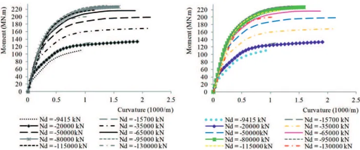
Figure 5
Moment-curvature diagrams given by CAPIBA (Souza Jr. [4]). No concrete coninement taken into account
Figure 6
To consider the elastoplastic behavior, AASHTO [10] recommends re-ducing the effects of seismic forces by a response modiication factor, since AASHTO is a force-based code. For critical operating class bridg-es pier walls AASHTO [10] considers a rbridg-esponse modiication factor of 1.5. Initially the bridge pier was designed following AASHTO [10] provi -sions, and since this is a force-based code, the response modiication factor was applied to reduce the elastic seismic stresses obtained after this analysis. After the pier wall was designed based on this assump-tion, its ductility capacity was evaluated based on CALTRANS [5] provi-sions and also by performing a pushover analysis.
4.3 Design of central pier wall
Table 1 presents the pier reinforcement summary. The transverse
reinforcement was determined by two criteria, corresponding to two levels of detailing and consequent concrete coninement, that inluence in ductility capacity. The irst criterion is according Brazilian Standard NBR6118 [8] referred to as usual detailing. The second one is according ACI-318 [9] referred to as special transverse detailing.
4.4 Pier wall ductility assessment according
to CALTRANS [5]
The moment-curvature diagrams obtained in CAPIBA Program (in Souza Jr. [4]) are shown in Figures 5 to 7. Tables 2 to 4 show the ductility capacity μc for all the cases previously defined. Figure
8 shows the relationships between dimensionless compression
Figure 7
Moment-curvature diagrams provided by CAPIBA (Souza Jr. [4]), ACI-318 [9] transverse reinforcement,
concrete coninement considered
Table 2
Ductility capacity, no concrete coninement taken
into account
Nd (kN) ηd μc
Unconined
-130000 -0.813 1.24 -115000 -0.719 1.24 -95000 -0.594 1.32 -80000 -0.500 1.43 -65000 -0.406 1.63 -50000 -0.313 1.97 -35000 -0.219 2.37 -20000 -0.125 3.45 -15700 -0.098 1.92 -9415 -0.059 1.90
Table 3
Ductility capacity, NBR6118 [8] transverse
reinforcement concrete coninement
Nd (kN) ηd μc
Conined,
A
sw
NBR6118
forces (obtained by Equation 14) versus ductility capacity.
(14)
4.5 Nonlinear static pushover analysis
Four types of models where created in order to perform the nonlin-ear static pushover analysis: three-dimensional model and springs simulating the soil-interaction between the piles and the soil; three-dimensional model and ixed piles; two-three-dimensional model and springs simulating the soil-interaction between the piles and the soil; and two-dimensional and ixed piles. The displacements and ductility capacity are given in Table 5.
4.6 Results discussion
Analyzing the moment-curvature diagrams and the ductility
ca-pacity values obtained for unconined concrete, conined con -crete according NBR6118 [8] transverse reinforcement detailing, and conined concrete according ACI-318 [9] transverse rein -forcement detailing, it is clear that as the compression on the column increases from 0 ≤ η ≤ -0.13, ductility capacity increases as well. From certain compressive force values (η ≤ -0.13), duc-tility get smaller. For compressive strength values close to rupture (η ≤ -0.6), ductility becomes very low. It is also noticeable that for -0.1 ≥ η ≥ 0.5, there is a considerable enhancement in ductility if the effects of concrete coninement are taken into account. The more conined is the concrete, greater is its ductility. But for η ≤ -0.5, increasing the transverse reinforcement does not result in greater ductility capacity.
After performing nonlinear static pushover analyses, it can be seen that for the 4 types of models for which the analysis was performed, ductility capacity increases as the transverse reinforce-ment increases as well. It is noticeable that two-dimensional mod-els provided results that were very close to results obtained with three-dimensional models. Representing piles by their real length and springs for simulating the soil-structure interaction provides higher ductility values than ixing the piles in the model.
5. Conclusions
This study aimed to investigate the inluence of reinforcement detailing in ductility of reinforced concrete bridge central pier for different levels of detailing. For this purpose, different sets of rein-forced concrete levels of detailing were considered as design and detailing guidelines, based on ACI 318 [9], intermediate, and spe-cial detailing, and NBR 6118 [8]- ordinary detailing.
Member moment-curvature relationships were then obtained for each level of detailing, based on Mander’s [3] coninement model relations. Once the member moment-curvature diagrams were ob-tained, member ductility was found by the CALTRANS [5] approxi-mate method and by performing a non-linear pushover analysis. As expected, member ductility reduces as the level of axial compressive forces increases. From the moment-curvature
Table 4
Ductility capacity ACI-318 [9], transverse
reinforcement, concrete coninement
Nd (kN) ηd μc
Conined,
A
sw
A
CI-318
-130000 -0.813 1.50 -115000 -0.719 1.62 -95000 -0.594 1.89 -80000 -0.500 2.16 -65000 -0.406 2.69 -50000 -0.313 3.23 -35000 -0.219 3.84 -20000 -0.125 4.66 -15700 -0.098 2.11 -9415 -0.059 2.07
Figure 8
relationships it can be noticed that for certain compression val-ues (-0.1 ≥ η ≥- 0.5), as long as the concrete is suficiently con-ined, the strength drop is not abrupt. This can be valuable infor-mation when designing a bridge subjected to seismic actions. It is possible to assure a good bridge performance by regulating the compression rate to which the pier is subjected to. As long as the pier compression is in its optimal range, effective con-inement assures enough ductility. As long as the pier presents enough plastic deformation capacity, fragile rupture is avoided. It can also be concluded that determining ductility capacity by applying a response modiication factor may be too conserva-tive and uneconomical. A pier can achieve greater levels of duc-tility by adopting special detailing and therefore, at least a dif-ferent set of response modiication factors could be provided by bridge codes, accounting for the level of detailing adopted in the design. Summarizing, concrete piers can achieve ductility levels rather superior than the corresponding to the factors proposed by AASHTO [10], so the response modiication values could be revisited, and to different levels of detailing different response modiication factors could be deined.
After performing the nonlinear static pushover analysis, it can be seen, as expected, that for the 4 types of models where the analysis was performed, ductility capacity is greater as long as the transverse reinforcement increases. It is noticeable that two-dimensional models provided results that were very close to those obtained by three-dimensional models. It can be concluded that the two-dimensional models can present satisfactory results, and the simpliied two-dimensional nonlinear static pushover analysis can be adopted to ind a member ductility capacity. Representing piles by their real length and springs to simulate the soil-structure interaction results in greater ductility values than the obtained by
ixed piles, which is expected, since the base is more lexible and allows the structure to move more freely. Therefore, it is noticeable that obtaining member displacement capacity by equivalent length ixed piles provides conservative results.
6. References
[1] Associação Brasileira de Normas Técnicas, ABNT 2006, NBR-15421: Projeto de estruturas resistentes a sismos – Procedimento. Rio de Janeiro: ABNT.
[2] Chopra, A. K. 4th ed. 2012, Dynamics of Structures, Theory and Applications to Earthquake Engineering. Upper Saddle River: Pearson- Prentice Hall.
[3] Mander, J.B.; Priestley, M. J. N., 1988. Theoretical Stress-Strain Model for Conined Concrete. Journal of Structural Engineering, v.114, nº8, pp. 1804-1826.
[4] Souza Jr., P. J., 2012. Análise de Pórticos de Concreto Arma-do em Condições Sísmicas ConsideranArma-do o Modelo de Man-der. Rio de Janeiro: Universidade Federal do Rio de Janeiro, Escola Politécnica, Programa de Projeto de Estruturas. [5] California Department of Transportation, CALTRANS 2006,
CALTRANS Seismic Design Criteria. California: CALTRANS. [6] Sucuoğlu, H.; Akkar, S, 1st ed. 2014. Basic Earthquake En-gineering from Seismology to Analysis and Design. Cham: Springer.
[7] CSI Computers & Structures, Inc., SAP2000 v. 16, 2014, Integrated Software for Structural Analysis & Design. Berke-ley: CSI Inc.
[8] Associação Brasileira de Normas Técnicas, ABNT 2014, NBR-6118: Projeto de estruturas de concreto – Procedimen-to. Rio de Janeiro: ABNT.
Table 5
Ductility capacity after nonlinear pushover analysis on SAP2000 (2014)
Three-dimensional model. Flexible base
Nd (kN) ηd μc
Unconined -15700 -0.098 2.72 -9415 -0.059 2.31
Conined Asw NBR 6118
-15700 -0.098 2.99 -9415 -0.059 2.77
Conined Asw ACI-318
-15700 -0.098 3.35 -9415 -0.059 2.91
Three-dimensional model. Fixed base
Nd (kN) ηd μc
Unconined -15700 -0.098 2.49 -9415 -0.059 2.12
Conined Asw NBR 6118
-15700 -0.098 2.72 -9415 -0.059 2.54
Conined Asw ACI-318
-15700 -0.098 3.09 -9415 -0.059 2.66
Two-dimensional model. Flexible base
Nd (kN) ηd μc
Unconined -15700 -0.098 2.70 -9415 -0.059 2.30
Conined Asw NBR 6118
-15700 -0.098 2.96 -9415 -0.059 2.74
Conined Asw ACI-318
-15700 -0.098 3.38 -9415 -0.059 2.88
Two-dimensional model. Fixed base
Nd (kN) ηd μc
Unconined -15700 -0.098 2.42 -9415 -0.059 2.06
Conined Asw NBR 6118
-15700 -0.098 2.65 -9415 -0.059 2.45
Conined Asw ACI-318
[9] American Concrete Institute, ACI 2014, ACI-318-14: Building Code Requirements for Structural Concrete and Commen -tary, Farmington Hills: ACI.
[10] American Association of State Highway and Transportation Oficials, AASHTO 2010, AASHTO LRFD Bridge Design Speciications. Washington DC: AASHTO, 2010.