ABSTRACT: Based on coupled unsteady panel/free-wake method, a universal analysis model was established, which provides a good prediction for the rotor/fuselage unsteady aerodynamic interaction. Considering the deiciencies of the traditional time-marching rotor free-wake algorithms, notably on stability and eficiency, the CB3D algorithm with 3rd-order accuracy is proposed. For solving the problem that part of the wake vortices may penetrate the fuselage, a “material line” rectiication method with 3rd-order accuracy is proposed. An analysis for the model accuracy was then conducted to validate the accuracy of the new model, and a comparison against the available experimental data is performed. The simulated results show a good agreement with these experimental data. With the new model, several simulations are conducted for the typical rotor/fuselage aerodynamic interaction, and the results are analyzed.
KEYWORDS: Aerodynamic interaction, Panel method, Free-wake, Rotor/fuselage interaction.
The Theoretical Research for the
Rotor/Fuselage Unsteady Aerodynamic
Interaction Problem
Liu Dawei1, Xin Ji2, Huang Jun1
INTRODUCTION
he rotor unsteady aerodynamic interaction is one of the research hotspots of rotorcrat. It not only has a great inluence on aerodynamic general layout designing of helicopter, but also plays a more and more important role in helicopter light dynamic modeling and simulation. Many scholars from diferent countries have carried out researches on this issue. his paper focuses on the prediction model about the typical aerodynamic interaction of rotor-fuselage interaction.
Helicopter rotor low-ield simulation methods can be divided into 2 categories: Computational Fluid Dynamics (CFD) and free-wake. Serious non-physical dissipation happens when the CFD method is used to simulate the blade vortex interaction. In addition, a huge amount of computation is needed for CFD method to accurately predict the rotor low-ield. By contrast, the problems mentioned will not happen in free-wake model, so it is more suitable for the calculation of unsteady aerodynamics interaction in engineering application.
In the free-wake prediction approaches, comparing to relaxation iteration algorithm (Bagai 1995), the time-stepping free-wake method can not only simulate the steady light, but also predict the low-ield of a transient lying rotor. However, at present, the widely used PC2B algorithm (Bhagwat 2003) is a kind of predict-correction method. It has a relatively lower eiciency when considering the inluence of other boundary such as the fuselage. Recently a one-step CB2D algorithm was proposed (Li and Chen 2012) and it has a higher eiciency. But divergence of free-wake structure may happen when it is used to simulate the rotor interaction problems. So, considering the deiciencies
1.Beijing University of Aeronautics and Astronautics – School of Aeronautic Science and Engineering – Beijing – China. 2.China Helicopter Research and Developing Institute – Jingdezhen – Jiangxi – China.
Author for Correspondence: Xin Ji | China Helicopter Research and Developing Institute | Jingdezhen – Jiangxi – China | Email: [email protected]
of traditional CB2D algorithm on stability, an explicit CB3D algorithm with 3rd-order accuracy is proposed in this paper. CB3D eliminates the anti-dissipation efect caused by 2nd-order error terms in CB2D algorithm, which could improve the numerical stability, analysis accuracy and computational eiciency in the simulation of rotor aerodynamic interaction problems.
In the research of rotor-fuselage interaction, the literature (Bi and Leishman 1990; Leishman and Bi 1990; Smith and Betzina 1986) introduced several experiments on this issue, and the pressure distribution on fuselage surface was measured. In the theoretical analysis ield, some papers (Rand 1988; Lorber and Egolf 1990; Crouse et al. 1992) used a prescribed wake
method to predict the interaction low-ield. In view of the particularity of rotor-fuselage aerodynamic interaction, many empirical and ideal components were added into the analytical model, which limited its universal property and accuracy. he literature (Mavris et al. 1989; Xu et al. 2002; Quackenbush et al.
1999) used the more advanced free-wake method to simulate the rotor low-ield. In the free-wake model, only a few used tip vortices (Katz 2001) and others used a full-span free-wake model. For solving the problem that some of the wake vortices discrete points may move not physically into the fuselage surface, Lorber and Egolf (1990) placed the vortices near the fuselage as half-circle vortex segments around it, and some scholars placed the wake points which move into the fuselage in a mirror-image location. hese rectiication approaches lacked theoretical basis and then had a low rectiication accuracy, which may lead to a less accurate aerodynamic interaction analysis model.
A coupled unsteady panel/time-stepping free-wake method is established to predict the helicopter rotor interaction low-ield. he panel method is used to simulate the inluence of the helicopter fuselage. A “material line” rectiication method is proposed to solve the problem that part of wake vortices may penetrate the fuselage surface. To validate the accuracy of this model in rotor interaction, a comparison of free-wake structure, rotor aerodynamic performance and the pressure on fuselage against the available experimental data is carried out, and the simulated results agree well with the experimental data.
PREDICTION MODEL
ROTOR AND FREE-WAKE AERODYNAMIC MODEL he circulation of the blade bound vortex and the aerodynamic performance are calculated using the lifting surface theory. A series of vortex lattices are divided into the spanwise and
chordwise direction, respectively. he sketch of blade liting surface is illustrated in Fig. 1.
Vortex panelControl point Blade
Near wake
Tip vortice Vortex discrete point Rotor axis
z y
x
∆ζ ζ ψ
Figure 1. Figure of blade lifting and tip vortices.
From the experimental observations, the trailing vortices will roll up to a single tip vortex ilament within a few chords behind the rotor blades (about 30 – 60 degrees behind blade trailing edge). he tip vortex has been documented to be the most dominant structure in the rotor low-ield. he inboard trailers have a negligible inluence on the rotor performance.
But in rotor-fuselage interaction flow-field, since most part of the slim fuselage is just below the rotor blade root, the free-wake model only keeping tip vortex will be less accurate in the prediction of the pressure on fuselage surface. hus more sophisticated model is required to determine the rotor/fuselage interaction. Provision has been made to use a full-span free-wake model including 5 – 7 trailing vortices, as shown in Fig. 2. Circulation of the vortices is determined by the maximum circulations on both sides of the vortex release point.
Figure 2. Full-span free-wake geometry trailing from one blade.
In the free-wake method, the vortices are force-free and convect with the local air velocity. he motion is governed by the following equation:
ψ is the azimuth angle; ζ is the vortex age; Ω is the rotor rotational speed; uis thewake velocity; u∞is the free stream velocity; u
freewake-induce(ψ, ζ) and ufuselage-induce(ψ, ζ) are the velocities induced
by free-wake and fuselage, respectively, on vortices points.
CB3D NUMERICAL INTEGRATION SCHEME he original CB2D algorithm is shown in Eq. 2, where r
l,kis
the position vector of the kth vortex discrete point on a vortex line shed by blade located at the l-th azimuth angle; u(r
l,k) is the
velocity of the vortex point, and the term with a γ coeicient is the artiicial dissipative one proposed by Li and Chen (2012):
(2)
(4)
(3)
(6) (5)
Equation 2 is obtained based on the assumption that Δψ = Δζ, and its modiied equation (expanded at the point (l + 1/2, k + 1/2)) is as follows (u
ψ, ζ = ∂2u/∂ψ∂ζ):
Since the principal error terms on the right side of the equation are the 2nd-order ones, the CB2D is a 2nd-order accuracy algorithm.
According to Eq. 3 we can transform the error terms ((–5/12)g(1/Ω)gu
ψψgΔψ
2 – (1/3)g(1/Ω)gu ζ ζ gΔψ
2
) into
1/12 Ω ·(u
rrζ+ urrrζ 2
– 2(
uur)rrζ – 4u(uur)r)Δψ
2. As analyzed in the literature (Li and Chen 2012; Warming and Hyett 1974), the terms containing the 2nd-order partial derivatives r
ζζ and r
ζ
2 , which mainly play an anti-dissipation role in the free-wake iteration, because of their coefficient variables u
r, urr, often
become minus. So in the literature the artiicial dissipative term γΔψ2r
ζζ (γ ∈ (0, Δψ)) with a constant positive coefficient is
added to strengthen the numerical dissipative efect, improving the stability of the numerical scheme. In the present study, an approach is proposed to further improve stability of the scheme as follows.
Note the following existing relations:
he 2nd-order terms on the right side of the equations are just the error terms in Eq. 3. If the polynomials on the let side of Eq. 4 are added to the right side of Eq. 2, according to the coeicients of the corresponding terms in Eq. 3, then a new algorithm is obtained:
he modiied equation (expanded at the point (l + 1/2, k + 1/2)) of Eq. 5 is as follows:
Given that γ ∈ (0, Δψ) (Li and Chen 2012), Eq. 5 is an algorithm of 3rd-order accuracy. his algorithm is referred to as CB3D scheme in this study. Since the 2nd-order anti-dissipative terms in Eq. 3 have been eliminated, the stability of the new scheme should be strengthened.
From Fig. 3 we can see that the convergence speed of CB3D is faster than CB2D, and the wake geometry predicted by the 2 algorithms have got a little diference, which could be attributed to the diferent error terms in the modiied equations of the 2 algorithms.
Iteration step
x/R
lg [rms]
z
/R
0
–0.5
1
1.5 1
0 CB2DCB3D
–1
–2
–3
–4
–5
–6
–7
0 10 20 30 40 50
–2
–1 0 1 –1 0 1
–2.5
Figure 3. Comparisons of iterated convergence speed and wake geometry predicted by CB2D and CB3D. (a) Convergence speed of CB2D and CB3D; (b) Wake geometry predicted by CB2D and CB3D.
FUSELAGE MODEL
he interaction efects of fuselage on rotor low-ield are all added by the panel method. According to the low-speed aerodynamics (Katz 2001), the velocity potential ϕ at a point in
space induced by the panels is determined by the distribution of doublets μ and sources σ, as follows:
(7)
(8)
(10) (9)
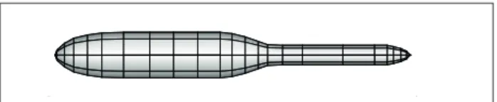
Figure 4. Discrete fuselage with panel method.
According to the research made by Katz (2001), the control point is set at the centroid of every element. he low-ield velocity on every control point needs to satisfy the no-penetration boundary conditions. For solving the doublet and source strength of every panel, the source panel strength can be written as Eq. 8:
where: V→∞ is the free stream velocity; V→freewake-induceis the
induced velocity at control point induced by the far-wake vortex; V→fuselageis the motion velocity of fuselage at control point.
Based on the relationship between velocity potential and velocity, combined with the no-penetration boundary condition on solid surface, the velocity at the ith control point should
satisfy the equation:
where: Bi,kand Ci,kare the induced velocity at the ith
panel element induced by the unit strength source or doublet distributed at the kth panel element.
We can get N equations of N panel elements like Eq. 9. he
source strengths σk can be achieved from Eq. 8, so the doublet
strengths can be obtained by solving the N-dimensional linear
equations. hen the induced velocity and the induced velocity potential at any point in the low-ield can be calculated.
Considering that the low on the fuselage is unsteady under the inluence of rotor interaction, the pressure and load on the fuselage is obtained through solving the unsteady Bernoulli Equation in:
(a)
(b)
where: Sf represents the whole boundary surface; r is the
distance from the doublet or source to the measured point;
n → is the local outward normal vector of the boundary surface.
he sources and doublets are uniformly distributed on every surface panel element. he discrete fuselage model is shown in Fig. 4.
where: P, V → and ϕ are, respectively, the pressure, velocity
in kg·m–3; R is the blade radius, in m; P
∞ is far-ield pressure;
Cpis deined as the non-dimensional pressure coeicient in this paper.
he studies of Crouse et al. (1992) and Quackenbush et al.
(1999) demonstrated that, in fuselage surface pressure determination, the unsteady term cannot be ignored. So, the unsteady term ∂ϕ/∂t is the aporia in unsteady low-ield
pressure prediction. If r is the distance from the potential panel to
the predicted point, that is r = √(x – x΄)2 + (y – y΄)2 + (z – z΄)2,
considering, ∂ϕ/∂x = (∂ϕ/∂r) g (∂r/∂x), we have, ∂ϕ/∂x΄ =
(∂ϕ/∂r) g (∂r/∂x΄) = 1g (∂ϕ/∂r) g (∂r/∂x), and the calculation
formula of ∂ϕ/∂t can be written as:
(11)
In Eq. 11, V→induce (x→) is the induced velocity of the potential
panel on the predicted point; V→ (x→) is the motion velocity of
the predicted point; V→source (x→ ΄) is the motion velocity of the
potential panel. So, in the case of a stationary fuselage, we can get ∂ϕ/∂t = –1g (V→induce (x→)) g (V→source (x→ ΄)).
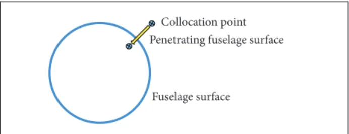
“MATERIAL LINE” RECTIFICATION METHOD he description of low-ield by the free-wake mathematical model is based on the Lagrange method. When updating the free-wake geometry on discrete temporal and spatial step, part of the wake vortices may not physically penetrate the fuselage surface as shown in Fig. 5.
Figure 5. The rotor wake collocation point “penetrates” fuselage surface.
Figure 6. Normal located wake collocation point and chosen auxiliary point at the last time step.
Collocation point Penetrating fuselage surface
Fuselage surface
Reverse extention line Auxiliary point Collocation point
Surface auxiliary point
Fuselage surface
not move inward solid surface to rectify the positions of the not physically located free-wake collocation points by interpolation. As shown in Fig. 6, in the rectiication, irst, at the last discrete time step when the wake collocation point is still outside the solid surface, a panel control point near the collocation point should be selected as an auxiliary point. he auxiliary point and the collocation point are connected with a straight line, then extend the line segment to another space auxiliary point, which is demanded to not penetrate the solid surface ater one time step and get as close to the collocation point as possible.
Considering the extended line segment as a luid material line, since one discrete time step is very short, the material line segment can be thought as a straight line segment ater one time step (Fig. 7). So, if the 2 auxiliary points do not penetrate the solid surface, all the points on the material line segment do not penetrate the solid surface, and the rectiied location of collocation point could be predicted by interpolation between 2 auxiliary points on the line segment.
In view of this problem, a “material line” rectification method is proposed in this section. he method is based on the fact that the luid micelles at the panel control points will
Figure 7. Location of the rotor wake collocation point after rectiication.
Surface auxiliary point Auxiliary point Reverse extention
line
Collocation point
Fuselage surface
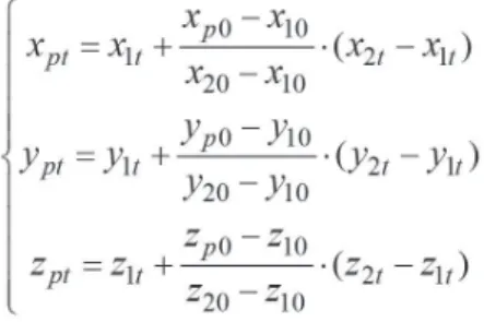
If we write the collocation point coordinates as (xp0, yp0, zp0),
the fuselage surface auxiliary point coordinates as (x10, y10, z10),
and the auxiliary point coordinates on the extended line as (x20, y20, z20), ater one time step, the coordinates of each of the
abovementioned 3 points can be written as(xpt, ypt, zpt), (x1t, y1t, z1t), and
(x2t, y2t, z2t), and the collocation point coordinates(xpt, ypt, zpt)
Figure 8. Space diagram and side elevation of rotor wake geometry at an advance ratio of 0.2.
Next, an accuracy analysis for the “material line” rectiication method will be given. Let us choose the rectiication formula as a representative sample for the analysis. If we consider
k = (zp0 – z10)/(z20 – z10), then we have:
(13)
(14)
(15)
(16)
(17)
At the last time step, the velocity on z direction can be written as Vz, then we have:
So the interpolation for collocation point location is an interpolation for its velocity in essence. Next, this section will give an accuracy analysis for point velocity interpolation.
If we set the surface auxiliary point as original point (subscript 1) and set l axis along the “material line”, the coordinates of space auxiliary point (subscript 2) in this coordinate system can be written as Δl. According to the proportional relation in Eq. 13, expanding Vz2 and Vz1 at location of the collocation point with a Taylor series, we can get:
Adding Eq. 15 and Eq. 16, we obtain:
(12) According to the former auxiliary points method chosen, the
magnitude orders of the material line length Δl and (V20 gΔt), that is (V20 g(Δψ/Ω), are close. From Eq. 17, we can see that the interpo- lation accuracy of “material line” rectiication method for velocity is of 2nd-order. So the interpolation accuracy of the method for location is O(Δl 2)gΔt, whose 3rd-order is in temporal discrete scale.
RESULTS AND DISCUSSION
SIMULATION AND ANALYSIS FOR ROTOR-FUSELAGE AERODYNAMIC INTERACTION
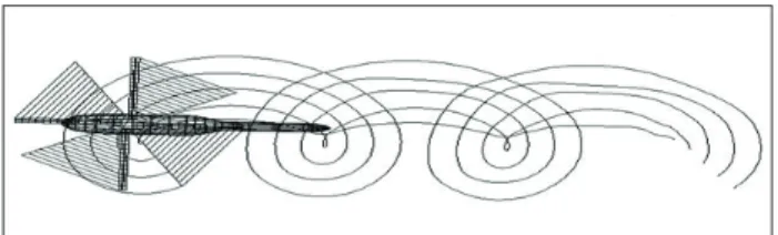
Leishman team conducted a series of experiments (Bi and Leishman 1990; Leishman and Bi 1990) about rotor-fuselage interaction phenomenon; the outlook of fuselage model they used is similar to the actual helicopter fuselage as shown in the let part of Fig. 4. In this section, the rotor/fuselage aerodynamic interaction of Maryland model in forward light is simulated and compared with measured data. Finally, the inluences of advanced ratio on unsteady aerodynamics interaction are analyzed. he simulated typical free-wake structure in interaction is shown in Fig. 8.
As can be seen in Fig. 8, in forward light situation, the free-wake vortex approaches the rear of fuselage. his indicates that the vortex-panel interactions become more intensive as the free-wake moves towards the backward of fuselage.
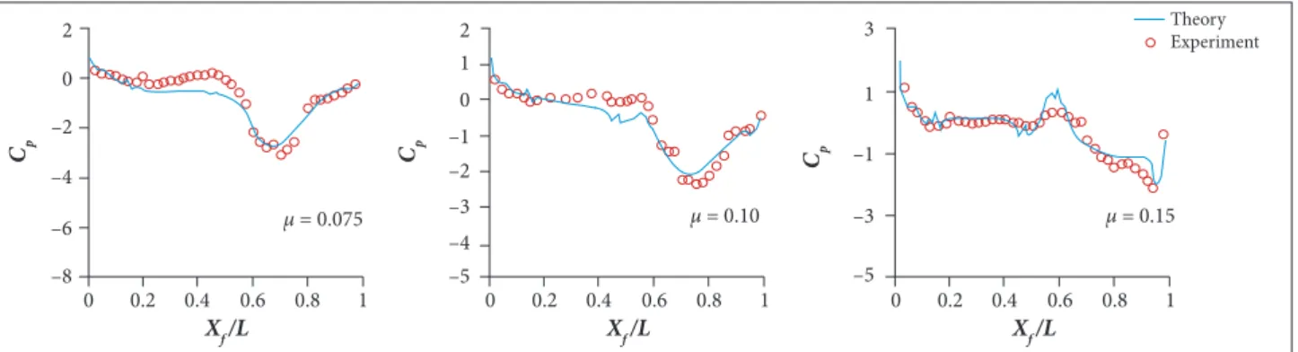
Figure 9. Comparison of predicted and experimental time average pressure on the left centerline of the fuselage surface at advance ratios of 0.075, 0.10 and 0.15 (C
T/σ = 0.085, αs = −6°, where CT is the rotor thrust coeficient and αs is the rotor shaft tilt angle).
0 –8 –6 –4 –2 0 2
0 1
–1 –2 –3 –4 –5 2
1
–1
–3
–5 3
1
0.2 0.4 0.6 0.8 0 0.2 0.4 0.6 0.8 1 0 0.2 0.4 0.6 0.8 1
μ = 0.075 μ = 0.10 μ = 0.15
Theory Experiment
Cp Cp Cp
Xf /L Xf /L Xf /L
From Fig. 9 we can also point out that, as the free stream velocity increases, the pressure coeicient on the fuselage nose increases. he negative peak of pressure coeicient emerges at the rear of the fuselage, which relects the location of vortex/ panel interaction and moves backward on the fuselage as the advanced ratio increases.
CONCLUSIONS
In this paper, an unsteady panel/time-stepping free-wake method is established to predict the helicopter rotor low-ield in aerodynamic interaction conditions. he panel method is applied to simulate the influence of helicopter fuselage on flow-field. A “material line” rectiication method is proposed to solve the problem that part of the wake vortices may penetrate the fuselage in numerical simulation. Considering the problem that the stability of traditional time-stepping free-wake algorithms is deicient for
the simulation of unsteady aerodynamics in rotor interaction, an explicit CB3D algorithm with 3rd-order accuracy is proposed. According to this study, a few general conclusions can be drawn:
• he coupled panel/time-stepping free-wake method is proved to be accurate and eicient for predicting the rotor low-ield of rotor-fuselage interaction. he simulated results are in good agreement with available experimental data.
• he “material line” rectiication method is lexible and has a 3rd-order precision. It is applicable to solve the non-physical motion problem encountered by the interaction between rotor wake geometry and solid surface. • Full-span free-wake model improves the simulation
accuracy of rotor/fuselage interaction phenomenon. As the free stream velocity increases, the pressure coeicient on the head of fuselage increases, and the negative peak of pressure coefficient at the rear of fuselage moves backward.
REFERENCES
Bagai A (1995) Contributions to the mathematical modeling of rotor flow-fields using a pseudo-implicit free-wake analysis (PhD thesis). College Park: University of Maryland.
Bhagwat M (2003) Mathematical modeling of the transient dynamics of helicopter rotor wakes using a time-accurate free-vortex methods (PhD thesis). College Park: University of Maryland.
Bi N, Leishman J (1990) Experimental study of rotor/body aerodynamic interactions. J Aircraft 27(9):779-788. doi: 10.2514/3.45938
Crouse L, Leishman J, Bi N (1992) Theoretical and experimental study of unsteady rotor/body aerodynamic interactions. J Am Helicopter Soc 37(1):55-65. doi: 10.4050/JAHS.37.55
Katz J (2001) Low-speed aerodynamics. 2nd edition. Cambridge: Cambridge University Press.
Leishman J, Bi N (1990) Aerodynamic interactions between a rotor and a fuselage in forward flight. J Am Helicopter Soc 35(3):22-31. doi: 10.4050/JAHS.35.22
Li P, Chen R (2012) Rotor unsteady aerodynamics model using an efficient free-vortex method. Aircr Eng Aerosp Tec 84(5):311-320. doi: 10.1108/00022661211255494
Lorber P, Egolf T (1990) An unsteady helicopter rotor-fuselage aerodynamic interaction analysis. J Am Helicopter Soc 35(3):32-42. doi: 10.4050/JAHS.35.32
Mavris D, Komerath N, McManhon H (1989) Prediction of aerodynamic rotor-airframe interactions in forward flight. J Am Helicopter Soc 34(4):37-46. doi: 10.4050/JAHS.34.37
flight mechanics. Proceedings of the 55th Annual Forum of the American Helicopter Society; Montreal, Canada.
Rand O (1988) Influence of interactional aerodynamics on helicopter rotor/fuselage coupled response in hover and forward flight. J Am Helicopter Soc 34(4):28-36. doi: 10.4050/JAHS.34.28
Smith C, Betzina M (1986) Aerodynamic loads induced by a rotor on a body of revolution. J Am Helicopter Soc 31(1):29-36. doi: 10.4050/JAHS.31.29
Warming R, Hyett B (1974) The modified equation approach to the
stability and accuracy analysis of finite-difference methods. Journal
of Computational Physics 14(2):159-179. doi:
10.1016/0021-9991(74)90011-4
Xu G, Zhao Q, Gao Z, Zhao J (2002) Prediction of aerodynamic interactions
of helicopter rotor on its fuselage. Chin J Aeronaut 15(1):12-17. doi: