Analysis of SiO
2
Thin Films Deposited by PECVD
Using an Oxygen-TEOS-Argon Mixture
CarlosE. Viana, Ana N. R.da Silva,NiltonI. Morimoto,
LSI-EPUSP,S~aoPaulo,SP, Brazil
and OlivierBonnaud
GMV,UPRESA6076, Universityof RennesI,Rennes,Frane
Reeivedon15May,2000
This study analyses the inuene of the argon ow on the Plasma Enhaned Chemial Vapor
Deposition(PECVD)of silionoxidethinlmsbyusingTEOSassilion soure. Theargonow
inreasesthedepositionrate,howeveritalsoanreatessomedefetsinthedepositedlm. Several
haraterizationtehniqueswereusedtoanalyzethedepositedlms. Thepreseneofargon,inthe
gasphase,modiestheplasmaomposition,thesurfaeroughnessofsilionwafer,andthesurfae
reation. Theoptimumargon owranges between65and 80sm to obtaina silion oxide thin
lmwithhighqualityintermsofrefrativeindex,smoothness,anduniformity.
I Introdution
Plasma Enhaned Chemial Vapor Deposition
(PECVD) by using tetraethylorthosiliate (TEOS),
as silion soure, isawell-known tehnique to deposit
silionoxidethinlms[1,2℄.Theadvantageofthis
teh-niqueistodepositsilionoxidewithahighrateandat
lowtemperature,that isompatiblewithalargerange
ofappliations. Indeed,aswellinverylargeintegrated
iruitproesswithverythinjuntionsasinlargearea
eletronis usingglass substrates,atemperaturelower
than600 Æ
Cisrequired[3℄. However,forthisratherlow
temperature, the silion oxide lm an present
stru-tural and eletrial defets. Thus, additional studies
areneededtooptimizetheproesstoimprovethe
ma-terial. Awaytomodifythelmpropertiesistohange
the dissoiation onditions of TEOS and thus to add
agas in theplasma. We propose, in this work,to use
a mixture of argon, oxygen and TEOS in the plasma
[4℄. Then,weanalyzetheinueneoftheargonowon
the silionoxide thin lmsdepositedby PECVDonto
silion substrate. The presene of argon modies the
plasma omposition and the deposition rate and also
anreatesomedefets,moreespeiallyattheSi/SiO
2
interfae. The main objetiveis thus to optimize the
qualityofthe silionoxidelm byhangingtheargon
ow.
Afterapresentationoftheexperimentalonditions
of the developed proess, several explanations of the
analysesandoptimalonditionsaredrawn.
II Experimental
Thehome made PECVD luster tool system, used in
this study, was desribed before [5,6℄. It has three
proesshambers,aloadlokandasample
manipula-tionhamber. Silionwafers(100),p-type,10-20.m,
75 mm in diameter were used assubstrate. The
sub-strateswereleaned usingthepiranhaandRCA
stan-dard leaning proesses followed by a dip in diluted
HF. The silion oxide depositions were arried out in
theonditionspresentedin Table1. TheTEOS,
oxy-gen, and argon gases are mixed in a speial hamber
before entering theproess reatorto guarantee a
ho-mogeneousmixture. Theargonow,expressedinsm,
istheanalyzedparameter.
From Ellipsometry measurements, using a
wave-length of 632.8 nm, the thikness and the refrative
indexweredetermined. Forthe wet ethingrate
mea-surement,weusedadilutedHFsolution(1:100).
The Composition of the plasma, in term of
moleulesand radials,isdedued from Optial
Emis-sion Spetrosopy (OES). Fourier Transform Infrared
Spetrosopy(FTIRS)wasusedtodeterminethe
hem-ialbonding statesof the lms. To evaluatethe
on-tamination as well at the Si/SiO
2
interfae as in the
Table1: proessparametersusedinallthesilionoxide
depositionproesses.
TEOSow(sm) 6.5
Oxygenow(sm) 450
Argonow(sm) 0to200
Proesspressure(Torr) 1
Temperature( Æ
C) 375
RFpower(W) 400
Distanebetweeneletrodes(mm) 10
Afterthedepositionproess,somesampleswere
an-nealed in a onventional furnae at 600 Æ
C during 12
hours, aluminum ontatMOS apaitorswere
imple-mentedforI-Vmeasurements.Thealuminumlayerwas
annealed at430 Æ
Cin forminggasduring 30min. The
nalapaitortestellareais300300m 2
.
III Results and Disussions
Theinueneofargonowonthedepositionand
eth-ingrateswereanalyzed.
Fig. 1showsthedepositionandethingratein
fun-tion of the argonow. One an observe tworegions.
Therst one(0-65 smof argon)in whih the
depo-sitionrate dereases, theseond one(100-200 smof
argon) in whih the deposition rate inreases. In the
rst region, the slight dereasing of the ething rate
showsthatthedensityofthedepositedlmsinreases.
This an be attributed to the argon bombardment of
the surfae, whih desorbs the ative speies. In the
gasphase,theeetoftheargonisnotsigniant,
de-spiteitshigheratomimassoftheargonionompared
withtheoxygen,beausethepartialpressureistoolow.
Intheseondregion,thesurfaebombardmentalways
inreasesbutthedepositionrateinreases,whihis
at-tributed to the higher ollision rate in the gas phase
promotingthedeompositionoftheTEOS[7,8℄. Butit
provokesalso struturaldefets asonrmed by AFM
and-Ramanresults.
Figure1. Depositionand ethingratesof thesilion oxide
lmsasa funtionof theargon ow. Aninreasingargon
owinduesrstadereaseandthenaninreaseofthe
de-positionrate withaorrelatedmodiation ofthe ething
The refrative index of the silion oxide lms was
1.4580.007andthuslosetothermaloxideone.
More-over,weobservedthat therefrativeindexhadno
sig-niantvariationin depth, during thewet ething
ex-periment. Thismeansthatdespitethevariationofthe
ethingrate,theompositionofthelmisalmost
on-stantandtheporosityremainslow.
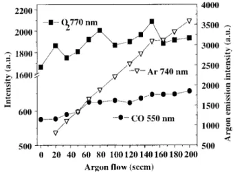
1) OESanalysis
To determine the omposition of the plasma and
to understand the role of argon ow, OES analysis
was performed [7,8℄. Fig. 2 shows the oxygen,
ar-bon monoxide, and argon optial emission intensities
in funtionofargonow.
Figure 2. OESmeasurementsofthe O,CO and Ar
emis-sionintensityinthegasphaseduringdeposition. TheCO
emission inreases with the argon ow suggesting an
en-hanementoftheTEOSoxidation.
TheslightandonstantinreaseoftheobservedCO
emissionsuggestsanenhanementoftheTEOS
oxida-tionproessbytheargonaddedtothegasmixture. An
inreaseofO
2
emissionisalsoobservedthatmeansthat
theargonenhanesthegenerationofexitedoxygenin
theplasma.
2) FTIRSanalysis
Fig. 3showsatypialspetraofthedeposited
sili-onoxide. Fortheargonow(0-65sm),weobserved
theregularstrething,bendingandrokingabsorbane
bands of silion oxide lms and also the Si-OH
ab-sorbane band. For higher argonow(100-200 sm)
the Si-OH absorbane band was not deteted
show-ing low hydrogen inorporation during the deposition
[9,10,11℄. Moreover,theindependeneofthespetra,in
funtionoftheargonow,onrmsthealmostonstant
Figure 3. FTIRSspetraofsamplesdeposited with
dier-entargonowsaddedtothetotalux. Thethreeobserved
peaksorrespondtosilion-oxygen bonds;noSi-OH peaks
arepresent.
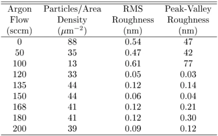
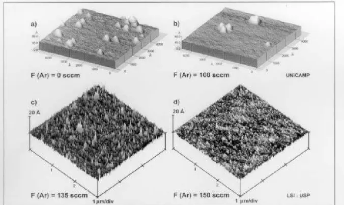
3) AFM analysis
Fig. 4 shows theAFM images of thesilion wafer
surfaeafterremovingthesilionoxidelayer.
First of all, an inrease of the argon ow, up to
100sm,leadstoaninreaseoftheaverageroughness
(seeTable2). Thisanbeexplainedbytheinreasing
bombardmentofthesilionsurfaeatthebeginningof
the deposition proess, by the morenumerous speies
presentintheplasma. Asmentionedabove,this
bom-bardmentalwaysinreaseswiththeargonow.
Forargonowshigherthan100sm,weobservea
strongdereaseoftheroughness. Thisbehavioranbe
explained by thebreakingof theadsorbedTEOS
sub-produtsatthesilionsurfaebythehigher
bombard-ment ofargonions. This bombardmentalso dereases
theinitialsilionroughness.
Moreover,oneanobservethepreseneofsmall
par-tilesatthesurfae,whihwerenotremovedbytheHF
solution treatment. These partiles are the unreated
[(Et-O)
3
Si-OH℄radialsremainingontothesilion
sur-fae. Aswellforthelowestasfor highestargonows,
the partile density is higher. This an be orrelated
to the deposition rate. When the deposition rate
in-reases,these adsorbedpartileshavenotreatedwith
oxygenandsomeofthemremainonthesurfaeandare
plasma bombardment, for high argon ows, promotes
aninreasingoftheroughnessanddefetsdensityofthe
silionsurfaeinreasingtheprobabilityoftrappingof
theunreated TEOSradials. Thisresultisonrmed
by-Ramananalysis.
Table 2: AFMmeasurementsobtained from the
sam-plesshowedin Fig. 4.
Argon Partiles/Area RMS Peak-Valley
Flow Density Roughness Roughness
(sm) (m
2
) (nm) (nm)
0 88 0.54 47
50 35 0.47 42
100 13 0.61 77
120 33 0.05 0.03
135 44 0.12 0.14
150 44 0.06 0.04
168 41 0.12 0.21
180 41 0.12 0.30
200 39 0.09 0.12
4.-RAMANanalysis
Puntualandlargedefets inthesilionoxidethin
lms are observed on -RAMAN images asshown in
Fig. 5.
Theso-alled\waferdefet"inthisgureisrelated
tothepre-existinglinedefetonthewafersurfae. We
expeted that the so-alled puntual defets have the
same origin. Fig. 6 shows the -RAMAN spetrum
madeinsidethepuntualdefet. ThepreseneofC=C
bondsonrmsthattheunreatedradialsaretrapped
bythesurfaestruturaldefets.
Thismeansthatthe\puntualdefets"are
arbon-based defets and ome from unreated TEOS
frag-mentsadsorbedat thesurfaeat thebeginningof the
deposition proess. Note that the wafer defets just
revealthis phenomenon. Oneannote that exept at
Figure4. AFMimagesofthesilionwafersurfaeafterremovingthesilion oxidelayer(usingadilutedHF 1:100H
2 O-DI
solution)andaordingtotheargonowvariation: a)withouttheargonow,b)100sm,)135smandd)150sm.
Figure5. -RAMANimageofsilionoxidelayerdeposited
withanargonow of135sm. Thesurfae appears
uni-formandsmoothexeptedatwaferdefets. Thesepuntual
defetsappearorrelatedtotheeetsobservedbyAFM.
Figure6. Typial-RAMANSpetrumofapuntualdefet
asshownFig. 5. Thearbonbondsonrmthepreseneof
2) EletrialCharaterization
Fig. 7shows typialJ-E urvesobtained from the
MOSapaitorsimplementedwithTEOSsilionoxide.
Table 3 shows the extrated parameters from the
J-Eurvesforseveralargonows. Theleakageurrent
density (J
LK
) values were obtained with a 4 MV/m
eletrialeld appliedtotheapaitors.
Figure 7. J-E urves from MOS apaitors implemented
with an argon ow of 65 sm. The annealing eet
de-reasestheleakageurrentdensityandinreasesthe
Table3: Leakageurrentand breakdown strength
a-ording the annealing time and as a funtion of the
argonowextratedfromJ-EurvesofFig. 7.
F
Ar
Annealing J
LK
(A)at E
BD
(sm) Time(h): 4MV/m (MV/m)
65 as-deposited 7:410 7
10.4
12 5:510
9
10.6
150 as-deposited 4:410 6
9.3
12 4:410
9
10.5
180 as-deposited 1:310 5
8.5
121:510 8
10.4
We anobserve an inreaseof theleakage urrent
densitywiththeargonow. Fortheas-deposited
sam-plesoneanobservethesamebehaviorafterannealing.
Theannealingeetivelydereasestheleakageurrent
density and inreases the breakdown strength. Thus,
thebestargonowrangesaround65sm.
IV Conlusions
Inordertoimprovethestruturalandeletrialquality
ofsilionoxidedepositedbyPECVDtehniqueandby
using TEOS assilion soure, we haveintrodued
ar-gon intheplasma. Wehavestudied silionoxidelms
depositedonmonorystallinesilionsubstrate. The
in-ueneofthepreseneofargonowin thereatorhas
dierent aspets. On one hand, whatever the argon
ow,therefrativeindex,measuredbyellipsometry,is
very lose to thermal oxide one that means that the
silionoxide isalwayslosetostoihiometri
omposi-tion. Ontheotherhand,aninreaseoftheargonow
dereasesrstthedepositionrateandtheninreasesit.
Inthe sametime,the roughnessof thesilionsurfae,
analyzed from AFM is ontinuously inreased due to
the bombardmentof additionalspeies present in the
plasma. Somepuntualdefets werealsodetetedbut
they appear at the strutural defets of the substrate
surfae. These arbon-baseddefets are more present
whenthedepositionrateinreasesasdetetedbyAFM
analysis beausetheyanberapidlyoverlayed.
Asaonlusion,by theargonowitispossibleto
get a silion oxide lm with high quality in term of
refrativeindex,smoothness,and uniformity. The
sili-onsubstrate surfaehasto befreeof defets to
min-imize puntual defets in thesilion oxide lm, whih
ould aet the eletrial behavior. Thebest results,
meansdenserlm,areobtainedforanargonowthat
rangesfrom65to80sm,thatorrespondsalsotothe
lowest leakageurrentdensity.
Aknowledgements
The authors aregrateful to Dr. M^onia A. Cotta,
N.M.HassanandDr. Sebasti~aoS. G.S.Filhoforthe
AFManalysis,toDr. M.L.P.Silvaforthe-RAMAN
measurements, to Dr. R. D. Mansano and Dr. L. S.
Zambon for their help at the leaning room, to
Car-losC. Nasimento and Gilberto K. Nishioka for their
tehnial support. Finanial support from FAPESP,
CNPq CAPES/COFECUB and FINEP are gratefully
aknowledged.
Referenes
[1℄ F.FraassiR.d'Agostino,andPFaviaJ.Eletrohem,
So.,139,2636 (1992).
[2℄ S.C.DeshmukhandE.S.Aydil,J.Va.S.Tehnol.B
14738(1996).
[3℄ K. Mourgues, F. Raoult, T. Mohammed-Brahim, D.
Briand,O.Bonnaud,Mat.Res.So.Symp.Pro.,471,
155(1997).
[4℄ C.E.Viana,A.N.R.daSilva,andN.I.Morimoto,
\Ar-gonInueneinthePETEOSSilionOxideDeposition
Proess", Pro. of International Conferene on
Miro-eletronisand Pakaging, Curitiba-PR (Brazil), 1998,
pp.481-483
[5℄ N.I. Morimoto, J.W.Swart, \A ClusterToolSystem
for Silion Oxide Deposition"; Pro. of X Congresso
daSoiedade Brasileira deMiroeletr^onia, Canela-RS
(Brazil),july1995,pp.393-409
[6℄ N.I. Morimoto, J.W. Swart\Developmentof a
Clus-ter Tool and Analysis of Deposition of Silion oxide
byTEOS/O
2
PECVD",RapidThermalandIntegrated
Proessing V, Mat. Res. So. Symp. Proeedings, vol.
429, 1996,pp.263-268.
[7℄ Y.Inoue, O.Tokai"Spetrosopi Studieson
Prepara-tionPlasmaSouresSi.Tehnol.,5,339(1996).
[8℄ R.Etemadi, C. Godet, and J. Perrin, Plasma Soures
Si.Tehnol.6,323(1997).
[9℄ P. Lange, L. Shmidt, M. Pelka, P. Hemiker, H.
BerntandWindbrake,J.Eletrohem.So.,139,1420
(1992).
[10℄ H.J.Shliwinski,etal.J.Eletrohem.So.,139,1730
(1992).
[11℄ S.K.Ray,C.K. Maiti, S.K.Lahiri, N.B.Chafrabarti,