UNIVERSITAT POLITÈCNICA DE CATALUNYA
Satyadhrik Sharma
Structural Analysis of the Masonry
Envelope of Ica Cathedral, Peru
Satyadhrik Sharma Str uctur al Anal ysis of t he Masonr y En
velope of Ica Cat
Structural Analysis of the Masonry
Envelope of Ica Cathedral, Peru
Name: Satyadhrik Sharma
Email: [email protected]
Title of the Msc Dissertation:
Structural Analysis of the Masonry Envelope of Ica Cathedral, Peru
Supervisor(s): Paulo B. Lourenço
Year: 2015
I hereby declare that all information in this document has been obtained and presented in accordance with academic rules and ethical conduct. I also declare that, as required by these rules and conduct, I have fully cited and referenced all material and results that are not original to this work.
I hereby declare that the MSc Consortium responsible for the Advanced Masters in Structural Analysis ofMonuments and Historical Constructions is allowed to store and make available electronically the present MSc Dissertation.
University: University of Minho
Date: 07 / 09 / 2015
Signature:
This thesis not only represents my work on the structural analysis of the Ica Cathedral in Peru. It represents a milestone culminating in one of the most productive years of my life: the year I have spent doing the SAHC masters.
I would like to take the opportunity to thank Prof. Paulo B. Lourenco for all he has provided to this thesis. He has truly been a supervisor in every sense of the word. Every minute of all the discussions were truly enriching in terms of my technical knowledge and in improving my experience in dealing with the structural analysis of historical constructions immensely. I would like to extend by heartfelt gratitude to Giorgos Karanikoloudis. It would have been next to impossible to get a better start to the thesis without the way he helped me. Even after the beginning, all the technical and non technical discussions we had regularly, along the entire period have contributed majorly to the shape of thesis as it lies completed.
Throughout the thesis, Dr. Nuno Mendes has offered amazing help and support with all problems relating with numerical modelling.
I would also like to thank the SAHC consortium for the financial support granted in the form of a scholarship, without which this fulfilling experience would not have been possible. I would also like to thank all my friends, colleagues in the University of Minho, whom I bothered regularly with my queries during this thesis.
My deepest gratitude to all my colleagues from SAHC during the coursework in Barcelona for gifting me one of the best seven months of my life. Giacomo, Inma, Marieta who came along with me to Guimaraes from Barcelona have been nothing short of family during my entire stay in Europe. Nirvan has been nothing short of another brother. His contribution to my stay in Europe including this thesis is something which is irreplaceable.
I would like to thank my family in India for their unwavering support through this intense year. The same goes for Devahuti, it has not been easy but it would have been much harder without your support.
Lastly but definitely not the least I would like to thank Maria Pia: sharing this entire experience with you has been nothing short of amazing.
Built in 1759, the Ica Cathedral is one of the four prototype buildings considered as a part of the Seismic Retrofitting Project (SRP) initiative of the Getty Conservation Institute. Under this project, the Ica Cathedral is considered representative of religious buildings built in coastal cities with a structural system consisting of thick mud brick walls and quincha vaults and domes. The Cathedral was also declared as a national monument of Peru in 1982.The Ica Cathedral currently exists in a state of disuse and in a heavily damaged state as a result of the 2007 Pisco earthquake and another subsequent earthquake in 2009.
This thesis primarily addresses the structural analysis of the masonry envelope of the Ica Cathedral. Based on existing information, a 3D model of the walls, base courses and bell towers of the structure was constructed. Consequently this model was used for creating a FE model in Midas FX+ for DIANA software in order to investigate various hypothesis of structural damage. A review of the results of the experimental campaign carried out under the banner of the SRP and existing literature was performed in order to input material properties into the numerical model. The created FE model was then updated in terms of material properties on the basis of ambient vibration tests performed on the cathedral recently. The nonlinear behaviour of the structure was investigated in the light of various static and dynamic simulations. Additionally the validated numerical model was also used to evaluate the effectiveness of a proposed strengthening scheme.
The present work was able to produce a numerical model validated in terms of existing damage. It was also able to make assesments of the seismic capacity of the cathedral and the effectiveness of the proposed strengthening in this regard. Nevertheless, further numerical modelling, including a combined model of the timber and masonry structures and subsequent structural analysis needs to performed in order to have a more conclusive assessment on the behaviour of Ica Cathedral.
Construída em 1759, a Catedral de Ica é um dos quatro edifícios protótipo considerados como parte da iniciativa SeismicRetrofitting Project (SRP) doGetty Conservation Institute. No âmbito deste projecto, a Catedral de Ica é considerada representativa de edifícios religiosos construídos em cidades costeiras com um sistema estrutural que consiste em paredes de adobe de elevada espessura e abóbadas e cúpulas de quincha. A Catedral foi declarada como monumento nacional do Peru em 1982.The Catedral deIcaencontra-se atualmente em estado de abandono e fortemente danificada como resultado do terremoto de Pisco em 2007 e outro terremoto subsequente em 2009.
Esta tese aborda principalmente a análise estrutural das paredes de alvenaria exteriores da Catedral. Com base nas informações existentes foi desenvolvido um modelo 3D das fundações, paredes e torres. Este modelo foi depois utilizado para a criação de um modelo de elementos finitos (EF) em Midas FX + para o programa DIANA a fim de investigar várias hipóteses de danos estruturais. Uma revisão dos resultados da campanha experimental realizadano âmbito do SRP e da literatura existente foi efetuada a fim de determinar as propriedades dos materiais a utilizar no modelo numérico. O modelo EF foi então atualizado em termos de propriedades dos materiais com base em testes de vibração ambiental realizados na catedral recentemente. O comportamento não linear da estrutura foi investigado em função de diferentes simulações estáticas e dinâmicas. Além disso, o modelo numérico validado foi igualmente utilizado para avaliar a eficácia de um esquema de reforço proposto.
O presente trabalho foi capaz de produzir um modelo numérico validado em termos de danos existentes. Foi também capaz de fazer uma avaliação da capacidade sísmica da catedral e da eficácia da solução de reforço proposta. Novos modelos numéricos, incluindo um modelo combinado das estruturas de madeira e alvenaria e subsequente análise estrutural deveria ser executada, a fim de ter uma avaliação mais conclusiva sobre o comportamento de Catedral de Ica.
Contents
1. Introduction ... 1
1.1 Objectives ... 3
1.2 Organization ... 4
2. The Ica Cathedral ... 7
2.1 History ... 8 2.1.1 Historical Background ... 8 2.1.2 Administrative Changes... 8 2.1.3 Church of Gesù ... 9 2.1.4 Seismic History ... 10 2.2 The Structure ... 11 2.2.1 Urban Context ... 11 2.2.2 Structural Description ... 11 2.2.3 Damage ... 18
3. Finite Element Model and Material Data ...23
3.1 Adopted Geometry... 24
3.2 Proposed Strengthening ... 27
3.3 Masonry Constitutive Behaviour ... 28
3.3.1 Fracture Process ... 28
3.3.2 Total Strain Rotating Crack Model ... 29
3.4 Review of Material Properties ... 31
3.4.1 Adobe Masonry ... 32
3.4.2 Fired Brick Masonry... 34
3.4.3 Rubble Stone Masonry ... 35
3.4.4 Timber ... 36
3.5 Material Properties for Strengthening ... 37
3.5.1 Geogrid-reinforced Adobe Masonry ... 38
3.5.2 New Brick Masonry ... 39
4.1.1 Dynamic Identification Techniques ... 43
4.2 Dynamic Identification of the Ica Cathedral ... 45
4.2.1 Test Parameters and Setups ... 45
4.2.2 Results ... 46
4.3 Model Updating and Eigenvalue Analysis ... 51
4.3.1 Model Updating ... 51
4.3.2 Eigenvalue Analysis ... 55
5. Nonlinear Structural Analysis ... 59
5.1 Self-Weight ... 61
5.2 Seismic Analysis ... 63
5.2.1 Pushover Analysis ... 63
5.2.2 Evaluation of Proposed Strengthening ... 74
5.2.3 Observations and Recommendations ... 77
5.2.4 Time History Analysis ... 80
6. Conclusions and Recommendations ... 99
6.1 Conclusions ... 100
6.2 Recommendations for further work ... 101
References
List of Figures
Figure 1: The Cathedral of Ica (Image: Scott S. Warren © J. Paul Getty Trust) ... 3 Figure 2: Floor plans of the Church of Gesù, Rome, and the Cathedral of Ica. ... 10 Figure 3: Location and surroundings of Ica Cathedral in the historic centre of Ica ... 11 Figure 4: Floor plan elucidating where wall prospections were performed (Drawing: José Garcia Bryce
and Mirna Soto for the GCI) ... 13
Figure 5: Southern bell tower structure (Drawing: José Garcia Bryce and Mirna Soto for the GCI) .... 15 Figure 6: Entrances to the cathedral-primary entrance in the eastern facade, entrances in the
northern lateral wall (Images: Sara Lardinois and Phillipe Garnier for the GCI) ... 16
Figure 7: Typical constructive details of the quincha pillars (Drawing: José Garcia Bryce and Mirna
Soto for the GCI) ... 17
Figure 8: Roof structure at the central nave and side aisles (Ciocci, 2015) ... 18 Figure 9: Roof structure at the crossing and transept (Ciocci, 2015) ... 18 Figure 10: Damage map of the front facade and bell towers (Drawing: Claudia Cancino for the GCI) 19 Figure 11:Horizontal and vertical cracking seen in the northern lateral wall ... 20 Figure 12:Damage map of the northern lateral wall (Drawing and photograph: PUCP for the GCI) ... 21 Figure 13: Location of altar and chapels in the Ica Cathedral ... 21 Figure 14: Damages in the roof structure of Ica Cathedral... 22 Figure 15: Representation of the FE Model: (a) 3D view; (b) plan view ... 24 Figure 16: Light weight roofing system seen in the sacristy, reception and other new constructions
present in the Ica Cathedral not included in the model. ... 25
Figure 17: Main entrance to the cathedral in the numerical model showing arched entrance (only for
a small part of the cross section) and timber lintel (for the remaining part of the cross section). ... 26
Figure 18: Cloister present adjacent to the southern lateral wall and 1 node springs simulating it in
the model. ... 26
Figure 19: Plan and elevation of the Ica Cathedral showing proposed strengthening scheme
(Drawing: D. Torrealva for the GCI). ... 28
Figure 20: Stress-displacement diagrams of quasi-brittle materials under tensile (left) and
compressive (right) loading (Lourenço et al., 1998). ... 29
Figure 21: Stress-Strain curve showing material model of masonry implemented in the numerical
model. ... 31
Figure 22: Schematic of the output-only technique of dynamic identification(Ramos, 2007)... 43 Figure 23: Measuring equipment: (a) accelerometer on the tower, (b): reference accelerometer on
the top of the northern longitudinal wall, (c) accelerometer on the pillar of the timber
structure(Greco et al., 2015). ... 46
Figure 24: Configuration of accelerometers in various test setups(Greco et al., 2015). ... 46 Figure 25: Data driven with the poles selection through the several test setups of the SSI-UPC
method(Greco et al., 2015) ... 47
Figure 26: Data driven with the poles selection through the several test setups of the SSI-UPC
method (Greco et al., 2015) ... 47
Figure 27: Comparison between the SSI-UPC and the EFDD results using the Modal Assurance
Criterion (MAC)(Greco et al., 2015) ... 49
Figure 28:Mode shapes obtained from the SSI-UPC Method, of the first three modes(Greco et al.,
2015). ... 50
Figure 29: Comparison of mode shapes obtained experimentally and selected numerical mode
Figure 31: Selected modes from modal analysis ... 57 Figure 32: Distribution of vertical displacements under self weight on the deformed mesh and
location of maximum vertical displacement. ... 61
Figure 33: Distribution of minimum principal stresses under self weight on the deformed mesh and
location of maximum compressive stress. ... 62
Figure 34: Distribution of maximum principal stresses under self weight on the deformed mesh and
location of maximum tensile stress. ... 62
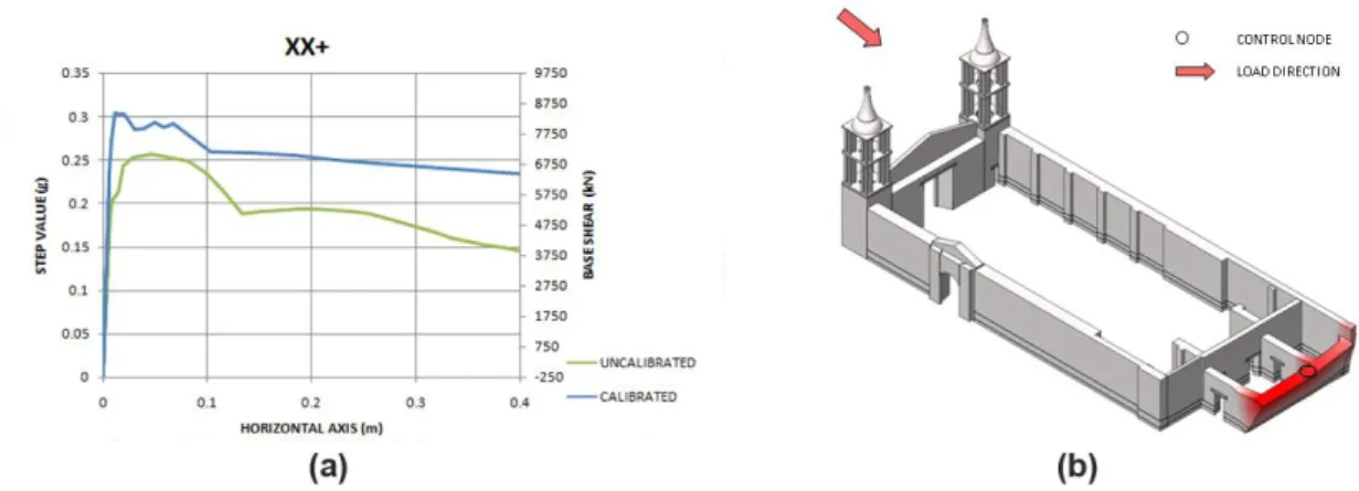
Figure 35: Response of the structure in XX+ direction: a) load displacement diagram and b) deformed
shape of the numerical model. ... 65
Figure 36: Crack pattern depicting the failure mechanism: a)global crack pattern; close up view of
b)vertical corner separation cracks c)base course flexural cracks ... 65
Figure 37: Disconnection and cracking of the upper end of the western wall of the altar (also
observed in situ) ... 66
Figure 38:Response of the structure in XX- direction: a) load displacement diagram and b) deformed
shape of the numerical model. ... 67
Figure 39: Crack pattern depicting the failure mechanism: a)global crack pattern; close up view of
b)vertical separation cracks and c) flexural cracks at the base ... 67
Figure 40: Crack pattern correlation: a) Numerical Model and b) In situ observations (Cancino et al.,
2012). ... 68
Figure 41: Response of the structure in YY+ direction: a) load displacement diagram and b) deformed
shape of the numerical model. ... 69
Figure 42: Crack pattern depicting the failure mechanism: a)global crack pattern; close up view of
concentration of tensile strains in b) north-western corner of the cathedral and c) near the northern bell tower... 70
Figure 43: Other regions of concentration of tensile damage in the numerical model during peak of
load displacement diagram. ... 71
Figure 44: Crack pattern co-relation: a) Numerical model and b) In situ observations (Cancino et al.,
2012). ... 71
Figure 45: Response of the structure in YY- direction: a) load displacement diagram and b) deformed
shape of the numerical model. ... 72
Figure 46: Crack pattern depicting the failure mechanism and close up view of shape of the segment
of the wall falling out of plane. ... 73
Figure 47: Other regions of concentration of tensile damage in the numerical model during peak of
load displacement diagram. ... 74
Figure 48: Response of the strengthened structure in YY+ direction: a) load displacement diagram
and b) deformed shape of the numerical model. ... 75
Figure 49:Crack pattern depicting the failure mechanism of a) strengthened model and b)
un-calibrated model ... 76
Figure 50: Crack pattern depicting the failure mechanism of a) strengthened model and b)
un-calibrated model ... 77
Figure 51: Seismic zones of Peru (Peruvian Code) and Ica location ... 80 Figure 52: Elastic response spectrum for the Ica Cathedral ... 82 Figure 53: Acceleration-time histories applied as base excitation to the model in two orthogonal
directions ... 83
Figure 54: Adopted variation of damping ratio along modes ... 85 Figure 55: Cracking in terms of principal tensile strains present globally in the structure... 88 Figure 56: Organization of the structure into various regions of interest to understand the dynamic
Figure 58: Time history of out of plane displacements of nodes on the top of the walls in region 1 and
4 (Y direction of the numerical model) ... 91
Figure 59: Base shear-horizontal displacement relationship in directions of dynamic loading of the
model. ... 92
Figure 60: Correlation of cracks observed from the numerical model and observed in situ on the
façade (Drawing:Cancino et al., 2012). ... 94
Figure 61: Correlation of various cracks in the interior part of the masonry envelope between the
numerical model and in situ observations: a) global crack pattern; b) near the southern bell tower; c) in the transept. Drawings: Cancino et al.(2012) ... 95
Figure 62: Correlation of various cracks between the numerical model and in situ observations: a)
List of Tables
Table 1: Historic seismic events affecting the Ica Cathedral ... 10
Table 2: Results of compression tests performed on adobe wallets from the Ica Cathedral(GCI & PUCP, 2014). ... 32
Table 3: Results of compression tests performed on brick masonry from Hotel El Comercio (GCI & PUCP, 2014). ... 34
Table 4: Material properties of different types of masonry input into the numerical model. ... 36
Table 5: Properties of Huarango timber species(GCI & PUCP, 2014). ... 37
Table 6: Comparison of mechanical properties between Geogrid-reinforced adobe and adobe masonry. ... 39
Table 7: Results of compression tests performed on brick masonry with new mortar from Hotel El Comercio (GCI & PUCP, 2014). ... 39
Table 8: Comparison of mechanical properties between new and existing brick masonry. ... 40
Table 9: Frequencies and damping ratios of the first three modal shapes – SSI-UPC Method(Greco et al., 2015). ... 48
Table 10:Frequencies and damping ratios of the first three modal shapes – EFDD Method(Greco et al., 2015). ... 48
Table 11: Comparison of numerical and experimental modal frequencies ... 54
Table 12: Comparison of numerical (calibrated) and experimental modal frequencies ... 55
Table 13: Comparison of Young’s modulus before and after model updating ... 55
Table 14: Modal participation masses for the first thirty modes in each direction ... 56
Table 15:Comparison of lateral load capacity of the calibrated and un-calibrated models in all four directions ... 78
Table 16: PGA values associated with seismic zones in Peru ... 80
Table 17: Soil Parameters for calculation of elastic response spectrum of Peru ... 81
Chapter 1
Structural analysis of historical masonry buildings represent some of the most challenging problems in the field of structural engineering. This thesis is focussed on the structural analysis and in particular the numerical modelling of such an construction: The Ica Cathedral in Peru.
Built in 1759, the Ica Cathedral is located in Ica, one of the most important cities on the coast of Peru. The cathedral is located in the corner of the city's historic centre and main plaza, at the intersection of two important streets: Jirón Libertad and Jirón Bolivar. Though currently in disuse after the 2007 Pisco earthquake, which severely damaged the structure, the cathedral has been used as a place of worship in the city under the ownership of various religious orders, changing hands numerous times with history.
The church was originally built by the Society of Jesus but following their expulsion in 1767 from the Viceroyalty of Peru, the Mercedarian Order took over the church in 1780. However the church is presently owned by the Roman Catholic Diocese of Ica which has been in possession of the church since their establishment in 1946.
Like most churches established by Jesuits, the Ica Cathedral follows the Jesuit typology modelled on the Church of Gesù in Rome. The basic layout of the cathedral consists of: a single central nave with four structural bays, a transept, an altar, and a choir loft-all covered by barrel vaults. Aisles flank the main nave on both sides and these aisles are covered with a number of small domes. Another large dome exists in the structure at the crossing of the nave and the transept. The domes and the barrel vaults are constructed with wooden arches and quincha(a local word used to indicate mixed timber-earthen construction). The lateral walls of the church are thick and constructed in mud brick masonry over courses of fired brick and rubble stone–the thickness of these layers vary in various parts of the church. The aisles are separated from the central nave by quincha pillars and arches covered with layers of gypsum plaster and mud. These structural elements are discussed in more detail in 2.2. Many similarities also exist with the Cathedral of Lima but these were incorporated mostly after the reconstruction works carried out in the late eighteenth century. Reconstruction and repair works were carried out in the cathedral after earthquakes which occurred in 1813
and 1942, and these are discussed in latter sections of this chapter. The structure is currently in a heavily damaged situation after the 2007 earthquake. The current damage includes primarily: partial collapse of the central dome, collapse of the barrel vaults near the facade, total collapse of the roof over one of the bays near the southern aisle and also loss of materials from various pillars and pilaster bases in the structure.
Figure 1: The Cathedral of Ica (Image: Scott S. Warren © J. Paul Getty Trust)
The following section of this chapter introduce the objectives that were considered before dealing with the case study being considered. The next section outlines how the work carried out to fulfil these objectives are organized in the main body of the thesis that follows.
1.1 Objectives
The main objectives of this thesis are summarized below:
To understand the geometrical and mechanical characterization of the structure. To perform a review of material properties from the experimental campaign
conducted on the same structure, existing literature in order to extract material parameters to be input into a finite element model of the structure.
To update the parameters of the model with results and observations from the site visit to the structure carried out by the team from the University of Minho.
To perform non linear finite element analyses on the numerical model: self weight loading, mass proportional pushovers and non linear dynamic loading in order to assess the safety and seismic capacity of the structure.
To validate the model in terms of its ability to reproduce the existing observed damages in the structure.
To use the validated model in order to simulate the proposed strengthening and evaluate its effect on the seismic capacity of the structure.
1.2 Organization
The work carried out in order to meet the objectives of the thesis, is organized into six chapters:
Chapter 1 introduces the motivation behind the thesis and its objectives. Also the organization of the work is presented here.
Chapter 2 presents both a historical and current survey of the cathedral. This chapter includes detailed information on the structural elements modelled in this thesis. The damage survey of the cathedral is also included.
Chapter 3 deals with three important parts of the thesis. Initially the finite element model is presented. The second part presents the strengthening proposed for the structure for which also another numerical model was constructed. The third part of this chapter deals with a review of all the material data used in the numerical model: constitutive law, mechanical characterization etc.
Chapter 4 presents the results of the dynamic identification tests carried out on the structure and how they were used to calibrate the model. The chapter also presents results of the eigenvalue analysis of the numerical model.
Chapter 5 presents the results of nonlinear analysis carried out on numerical model. The validated numerical model was also used to assess the proposed strengthening of the structure.
Chapter 6 presents conclusions from the works carried out. Additionally a few recommendations for further work are also mentioned.
Chapter 2
2.1 History
2.1.1 Historical Background
The city of Ica of which the cathedral is one of the most important buildings, has been inhabited since pre-Inca and Inca times. However, historically the city was claimed to be found by the Spanish conquerors in 1563. The first members of the Society of Jesus (Compañiade Jesus) who built the cathedral arrived in Peru in between 1567-1568. It is to be noted that the Jesuits were neither monks nor friars. Established in 1534 at the University of Paris, they were devoted to educational purposes. They often operated and lived in colleges. To maintain these educational establishments they often invested in farms which served for the purpose of money and also allowed them to interact with the rural population. Likewise in Peru they were associated with a number of farms in the Ica region at places like Mamacona, Belén, Caucato and San Jerónimo.
The Jesuits arrived in Ica in 1739 to open the College of San Luis Gonzaga. The building housing the cathedral at present was in fact originally intended to house this college. Work on the structure started in 1746 and was completed in 1759 if the inscription on the dome of the cathedral is to be believed. However the construction continued even after this date if other historical sources are to be believed, as master mason Gaspar Urrunaga was apparently working at the Jesuit college in Ica from 1762 to 1767, when the Jesuits were eventually expelled from Viceroyalty of Peru(Harth-Terré, 2003).
2.1.2 Administrative Changes
After the expulsion of Jesuits from Peru, the Ica Cathedral changed hands a number of times among various religious orders who not only occupied and renamed the cathedral but also altered and repaired the structure.
Notable among these are the Mercedarians who took over the church in 1780. The college was renamed as Colegio Mercedario de San Jose and the church was dedicated to Our Lady of the Mercy. The main altarpiece was also elaborated in 1802 by them. The church along
with a number of other buildings was damaged in an earthquake in 1813. The church was repaired by the Mercedarians following this. Notably the Neoclassical facade that exists now was built following the damage in this earthquake. The choir loft that exists presently was also possibly built at that time as such choir lofts are very uncharacteristic of Jesuit churches. The Mercedarians also had to leave Ica during 1821-1824 when Peru gained its independence and many religious orders were being suppressed. The college took back its former name of San Luis Gonzaga and the church took the name of Iglesia Matriz de San Jeronimo from a neighbouring church, which used to be the city's main church previously but was damaged in the earthquake of 1813.Several alterations were carried out in the nineteenth century but notable among these was the repairing of damages in 1874 which occurred during another earthquake in 1868.
The year of 1946 finally saw the establishment of the Roman Catholic Diocese of Ica with the former Jesuit College as its cathedral. The cathedral functioned as a place of worship for the diocese till the 2007 earthquake when it was damaged extensively. Even now the cathedral is still used by the priests of the diocese to celebrate mass occasionally in the damaged structure.
2.1.3 Church of Gesù
The floor plans of most Jesuit churches are based on the Church of Gesù in Rome and the Ica Cathedral is no exception. Typically Jesuit churches have floor plans which are in the form of a cruciform or a rectangle. The nave of such churches is often covered by very high barrel vaults and is flanked by low side aisles. These are divided into a number of square spaces, each covered by a dome. They continue to form the shallow transept which in turn is also covered with a barrel vault. The crossing of such churches are typically covered with a large dome holding up a lantern. However the Ica Cathedral shows a marked deviation from the floor plan of the Church of Gesù in the fact that the altar terminates in a flat wall instead of a semi-circular apse. The similarities in their floor plan are better elucidated in Figure 2.
.
Figure 2: Floor plans of the Church of Gesù, Rome, and the Cathedral of Ica.
2.1.4 Seismic History
The Nazca and South American tectonic plates meet near the Peruvian coast and earthquakes due to thrust faulting make Peru a very seismic zone. Historically, the Ica Cathedral has suffered damage due to a number of earthquakes which affected Peru after it was built. These earthquakes are tabulated in Table 1. It is to be noted that the damages incurred after these historical earthquakes were repaired and the church is currently in a state of disuse after the 2007 Pisco earthquake. Even more recently the already existing damages after the 2007 earthquake were aggravated by another earthquake in 2009.
Table 1: Historic seismic events affecting the Ica Cathedral
Date of Occurrence Magnitude Location
2009 5.8 Central coast of Peru 2007 8.0 Near the coast of central Peru 1942 8.2 Off the coast of central Peru 1868 9.0 Africa, Peru (now Chile) 1813 7.5 Ica, Peru
2.2 The Structure
2.2.1 Urban Context
Located at the intersection of two important streets in the historic centre of Ica: Jirón Libertad and Jirón Bolivar, the Ica Cathedral is located in the corner of an urban block rather than the middle of a city block. This makes the building more vulnerable in the event of an earthquake. On the east, near the front facade there is a 280m2 walled forecourt. On the
southern side, the church is an adjacent partly to a cloister and single storey mud brick construction which previously housed the Jesuit College and now houses a university. A three storey concrete structure and fired brick structure lie right next to the cathedral from the west.
Figure 3: Location and surroundings of Ica Cathedral in the historic centre of Ica
2.2.2 Structural Description
The cathedral has rectangular 22.5×48.5m floor plan oriented along the east-west axis. The total plan area of 1,075m2 is organised into ten functional spaces which are separated by
changes in floor level, interior pillars, pilasters and piers. More important than functionally ICA CATHEDRAL
CLOISTER NEW BUILDINGS JR. LIBERTAD
the Ica Cathedral can be divided into two substructures from the point of structural response:
The masonry envelope and the bell towers The timber framed interior structure
This thesis is focused on the numerical modelling of mostly the first substructure, being carried out in parallel with another thesis on the timber structure (Ciocci, 2015). Consequently, the sections that follow contain a more detailed structural description of the substructure being modelled here. A brief overview of structural details of the latter substructure is also provided.
Structural details of the masonry envelope and the bell towers which are very important for the finite element model developed are organised into the following sections: Foundation and Base Course; Fired Brick Facade; Load Bearing Lateral Walls; Bell Towers; Openings in the masonry envelope/ Entrances to the cathedral.
Foundation and Base Course
The Ica Cathedral is constructed over a base course constructed in fired brick masonry, rubble stone masonry or a combination of both. The base course in turn lies over foundations consisting of rubble stone masonry walls. The configuration and dimensions of the base course as well as the foundation vary considerably in the structure. However information about this is available only from the very limited number of wall prospections performed in the masonry. Information available from such prospections (Figure 4) are elucidated in the detailed description of various structural components that follows this section.
Figure 4: Floor plan elucidating where wall prospections were performed (Drawing: José Garcia Bryce and Mirna Soto for the GCI)
Fired Brick Facade
The 21 m long facade is constructed in fired brick masonry with lime mortar. The facade which was constructed in Neoclassical style after getting extensively damaged in 1813 due to an earthquake, largely defines the exterior appearance of the cathedral. The facade is characterised by the presence of large arched doors, Corinthian columns flanking them and a pediment on top. It is very interesting to note that the front facade reduces in its thickness and henceforth its slenderness ratio with height. The base is the thickest with a thickness of almost 2.25m while at the top it is about 0.30m thick. The facade rests on a foundation of rubble stone that is wider than the wall above the ground projecting almost 0.15m beyond the face of the wall and extends for a depth of 1m. A lack of proper connection is seen between the pediment and the lower part of the facade. The weak connection along with the highly changing slenderness ratio along with height of the facade makes the pediment highly susceptible to lateral overturning. Then, a choir loft, which was also added most probably to the cathedral at the same time as the facade was constructed, has a 0.10m embedment of its timber joists into the facade. The bases of the bell towers which are also constructed in brick masonry project from the two ends of the brick facade.
Lateral Walls
The two lateral walls in the church are both constructed in masonry of mud bricks and mud mortar. They have a slenderness ratio of approximately 3.35 and can be considered very thick. In fact their high thickness and consequently slenderness ratio (less than 5) make them very resistant to lateral overturning during earthquakes(Tolles et al., 2002). Though only a single wall prospection was performed per each of the lateral wall during previous investigations, it is known that the configuration of the foundation and base course is different in the lateral walls. The northern lateral wall rests over a 0.90m high fired brick masonry base course on top of a 0.40m rubble stone masonry wall. The height of the base course in southern lateral wall is 0.60m while the rubble stone wall is 0.48m deep. The lateral walls have a series of piers also constructed of mud bricks which lie behind each of the wooden pilasters in side aisles. Fired brick reinforcement is used at the connections between the piers and the lateral walls. These piers also have brick bases, but the bricks of these brick bases do not interlock with the brick base course of the adjacent lateral walls.
Bell Towers
The cathedral possesses two bell towers each approximately 3.80 × 3.80 m in plan. The bell tower structure consists of timber framed upper part which rests on a fired brick base projecting from the facade. The upper timber structure consists of vertical wooden posts which are connected to wooden plates that are embedded in the brickwork of the base. Horizontal wooden joists connected to the posts with half lap joints are used to create intermediate levels within the upper structure. Diagonal wooden framing is used to reinforce the posts. The timber framing of the bell tower is wrapped with a wire mesh lath covered with cement plaster finish. Originally however there used to be a gypsum plaster finish on canes which wrapped the voids in between the posts. In fact the entrance to the choir loft and the roof is provided by an opening in the southern bell tower which leads to a spiral staircase. It is also interesting to note that the nature of base course and foundation has been discovered to be markedly different at the connection of the bell towers to the walls. Detailed information is available only about the nature of this at the connection between
the northern bell tower and wall, where the rubble stone base course is interspersed with courses of bricks and extends up to a height of 1.75m above the floor level above. Then, there exists fired brick masonry for another 3m. Constructive details of the bell tower structure are explained in more detail in Figure 5.
Figure 5: Southern bell tower structure (Drawing: José Garcia Bryce and Mirna Soto for the GCI)
Openings in the masonry envelope/ Entrances to the cathedral
There are a total of three entrances to the cathedral. The main entrance is a pair of large arched doors present in the fired brick front facade facing the east. Access is also provided directly to the nave of the church by another set of large doors present in the northern lateral wall along Jirón Cajamarca. A third entrance also exists along the northern lateral wall which provides direct entrance to the sacristy. Access to the roof and the choir loft is provided through an entrance in the south eastern bell tower.
Figure 6: Entrances to the cathedral-primary entrance in the eastern facade, entrances in the northern lateral wall (Images: Sara Lardinois and Phillipe Garnier for the GCI)
The interior timber framed structure of the cathedral comprise of: Quincha Pillars and Pilasters; The Roof Structure.
Quincha Pillars and Pilasters
The main nave of the cathedral is separated from the side aisles by a number of wood- framed quincha pillars. These pillars spaced 5m apart from each other support not only the barrel vault over the nave but also the beams and joists which support the domes over the side aisles. Four similar pillars are present at the crossing of the nave and the transept, and these support the main dome present at the same location.
These pillars basically consist of eight 0.20×0.20 m and 0.20×0.10 m vertical wood posts connected either to an arcade plate or a beam with the help of dowels on the top; and nailed to a sill plate embedded in the fired brick base course. These posts are additionally reinforced by 0.07×0.07 m horizontal and diagonal wooden members also connected by dowels. A huarango tree trunk having diameter approximately 0.33m is located in the centre of each of these pillars, supporting but not connected to the arcade plate on its top and connected to embedded sill plate below. These pillars are finished with flattened cane reeds or cana chancada, typical of quincha constructions which are nailed to wooden battens, which in turn are nailed to the posts. The cana chancada are finally coated with a layer of plaster.
A number of similar but smaller pilasters exist along lateral walls adjacent to the mud brick piers reinforcing the lateral walls. These pilasters are constructed of four vertical wooden posts and they do not have the tree trunk in their centre. The pillars in the nave are connected to each other as well as to the pilasters near the lateral walls by wooden arches spanning in both the east-west direction as well as the north-south direction. Both the pillars and pilasters are supported on bases made of fired brick. More details of the structure of the quincha pillar are seen in Figure 7.
Figure 7: Typical constructive details of the quincha pillars (Drawing: José Garcia Bryce and Mirna Soto for the GCI)
Roof Structure
The roof structure of the Ica Cathedral is quite complicated and consists entirely of quincha. The main components of the roof structure are as classified below: Barrel vaults over the central nave, transept and altar; A large dome at the crossing of the nave and transept; Smaller domes over the side aisles; Five perpendicular lunette vaults intersecting the main
barrel vault on each side of the nave corresponding to the location of windows in the upper nave wall. Construction details of the timber roof are elucidated in Figure 8 and Figure 9.
Figure 8: Roof structure at the central nave and side aisles (Ciocci, 2015)
Figure 9: Roof structure at the crossing and transept (Ciocci, 2015)
2.2.3 Damage
The following sections of the thesis deal with the damage and other structural irregularities that exist currently in the structure. Like the previous section, more emphasis is laid on the damage seen in the part of the Ica Cathedral that is, mostly, numerically modelled in the scope of this thesis, i.e. the masonry envelope and the bell towers.
The damage and irregularities that exist currently are again organised as: Front Facade and Bell Towers; Lateral Walls; Altar and Roof Structure and other important damages.
Front Facade and Bell Towers
The front facade is characterised by horizontal cracks which exist at the connection between the pediment and the lower facade. Diagonal cracks suggesting pounding of the bell towers during seismic events also exist between the upper cornice and the base of the bell towers. In addition to this damage, the timber framed structural part of the bell towers is deteriorated and this poses a risk to the roofing system of the cathedral to the west. The deterioration seen includes failure of the connections between the timber members, change in position of a few timber elements from their original position (especially in the southern tower) and also termite damage.
Lateral Walls
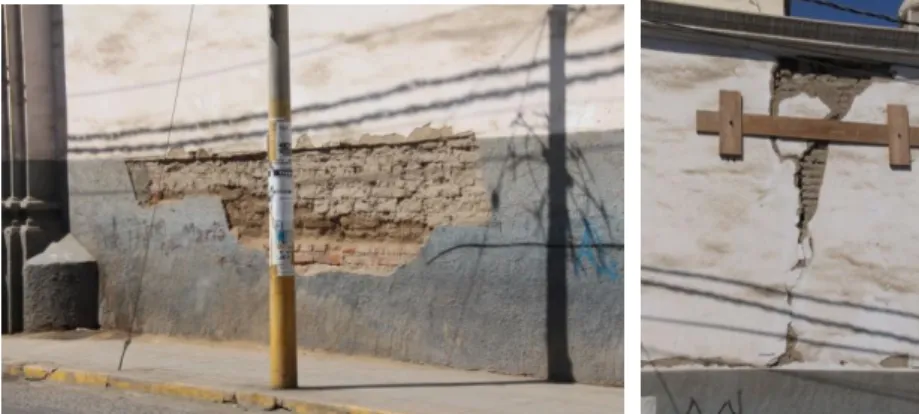
The damages and irregularities that exist in the northern and lateral walls are summarised here:
Horizontal and vertical cracks in the northern lateral wall along the perimeter of piers and arches adjacent to the choir loft.
An irregularity in construction seen is the fact that the bricks at base of the quincha piers do not interlock with the bricks of the base course of the lateral walls. This might be a possible cause behind the vertical cracking seen at the connection between the piers and the lateral walls (especially the southern lateral wall).
The southern lateral wall also suffers from humidity problems. This is most probably the result of improper drainage in the cloister of the Jesuit College which exists right next to this wall. Moisture problems have led to considerable degradation of the mortar and consequently of the masonry in the stone foundations of the southern wall, especially in the lower east end.
Horizontal cracks also exist at the upper and lower levels of the northern lateral wall in all the altarpiece spaces.
Both the southern and northern walls show horizontal cracking in their lower parts in the vicinity of the transept.
Figure 12:Damage map of the northern lateral wall (Drawing and photograph: PUCP for the GCI)
Altar
The altar, sacristy and chapels of the Ica Cathedral are located at its western end. Though no in-depth damage survey was carried out in the sacristy, the damages located in the altar and the chapels are well documented. These include:
Cracking, disconnection and out of plane movement of the upper end of the western wall of the altar and the southern chapel.
Vertical cracking in the corners of the walls of both chapels.
The upper parts of the northern and southern walls of the altar exhibit horizontal cracking. Similar cracking is exhibited by the southern and western walls of the northern chapel.
Figure 13: Location of altar and chapels in the Ica Cathedral
CHAPEL
ALTAR SACRISTY
Roof Structure and other important damages
The main damages seen in the Ica Cathedral are mostly in the roof structure, namely: Partial collapse of the central dome; Collapse of the barrel vaults near the facade above the choir loft; Total collapse of the roof over one of the bays near the southern aisle. In addition to these main damages extensive cracking, displacements, disconnection among structural members and other damages are seen in the interior, as well as the roof structure of the Ica Cathedral.
Chapter 3
This thesis is focussed on structural analysis of the masonry envelope of the Ica Cathedral using a finite element representation with a macro-model approach (Figure 15). The model is based on geometric and inspection surveys performed by the Getty Conservation Institute as part of the Seismic Retrofitting Project. Additional information was obtained by a site visit to the structure conducted during May-June 2015, by a team from University of Minho. Emphasis has been laid on reproducing the existing structural damage, the safety assessment of the structure in its current condition, the evaluation of the dominant mode shapes of the structure as predicted by the model, and also the comparison with the dynamic identification performed during the on site visit. This has been done by performing nonlinear static, eigenvalue, pushover and time history analyses, which will be addressed in subsequent Chapters.
Figure 15: Representation of the FE Model: (a) 3D view; (b) plan view
In addition to assessing the current condition of the church, a finite element model was also constructed based on the strengthening of the cathedral proposed by PUCP Peru on behalf of the Getty Conservation Institute. A detailed description of both finite element models can be found in this chapter.
3.1 Adopted Geometry
A 3D finite element model of the Ica Cathedral in its current state was constructed in Midas FX+ Version 3.3.0 Customized Pre/Post processor for DIANA software. This model was generated from the geometric survey carried out by the Pontificia Universidad Católica del Perú for the Seismic Retrofitting Project of The Getty Conservation Institute. The model as seen in Figure 15 includes the fired brick masonry facade, the bell towers, and the northern and southern lateral walls. The model however stops at the altar and the adjoining lateral
chapels. The regions in the cathedral housing the sacristy, reception and offices are not included in the model as from the visit conducted to the structure during May 2015, they were observed to be new structures with light weight roofing systems, not acting as a part of the masonry envelope, as seen in Figure 16.Therefore, these elements are likely to exhibit an independent behaviour from the parts of interest to this thesis.
Figure 16: Light weight roofing system seen in the sacristy, reception and other new constructions present in the Ica Cathedral not included in the model.
As per boundary conditions, all the nodes at the base of the structure were considered to be pinned, i.e. all the nodes have their translational degree of freedoms in three directions fixed to zero. All intersecting walls are assumed to have full connectivity. Full connectivity is also assumed between the fired brick base course and the adobe masonry parts of the wall and between the fired brick base course and the rubble stone base course foundation. It is also important to note that all the timber elements in the bell tower are also assumed to be rigidly connected, meaning that the stiffness and strength of the connections among these timber members are not considered in this model.
All the openings in the adobe masonry were assigned timber elements. Though no detailed geometrical information is available about their presence, the conducted damage survey shows that no significant damage is present near the openings. Thus the openings were provided with 30cm thick linear elastic timber lintels each having a bearing length of 50cm into the walls. This is illustrated in Figure 17.
Figure 17: Main entrance to the cathedral in the numerical model showing arched entrance (only for a small part of the cross section) and timber lintel (for the remaining part of the cross section).
Though the finite element model constructed does not include it, the constraining effect of the cloister which is adjacent to the southern lateral wall was taken into account. The presence of this cloister and consequently its stiffening effect on the southern lateral wall was simulated by the presence of 1-noded spring-dashpot elements. These spring elements were provided along the entire length of the southern lateral wall. The stiffness of each of these springs was calculated by calculating the stiffness of each of the columns present in the cloister. The stiffness hence calculated was multiplied with the number of columns present in the cloister to obtain the entire stiffness provided by the cloister. This was increased further to account for the presence of other vertical elements and lateral walls. The number finally obtained was divided by the number of nodes present on the mesh on the lateral wall corresponding to the height and thickness of the vault of the cloister present.
Figure 18: Cloister present adjacent to the southern lateral wall and 1 node springs simulating it in the model.
The created FE mesh for the model of the Ica Cathedral in its current state is composed of353,866isoparametric linear elements TE12L, 345one-noded translation spring dashpot elements SP12R and 81,236 nodes in total (TNO DIANA, 2014).
The FE mesh for the model of the Ica Cathedral considering the strengthening suggested for the masonry envelope is composed of 337,488 isoparametric linear elements TE12L, 338 one-node translation spring dashpot elements SP12R and 83,993 nodes in total(TNO DIANA, 2014).
3.2 Proposed Strengthening
As stated above, a FE model was also constructed considering the strengthening proposed by PUCP Peru on behalf of the Getty Conservation Institute. This section deals with the strengthening proposed only for the substructure of the Ica Cathedral being modelled in this thesis.
The proposed strengthening of the masonry envelope of the Ica Cathedral involves basically two procedures: replacing sections of the adobe masonry in the lateral walls with new brick masonry and reinforcing a part of both the walls with the help of geogrid nets. More information on how these strengthening procedures are assumed to change the material properties of the assigned sections of the structure in the numerical model are mentioned in It can be seen from Figure 19 that the proposed strengthening scheme involves only replacing and reinforcing portions of the adobe masonry and not the fired brick base course. The red portions in Figure 19 indicate regions to be replaced with new fired brick masonry while the shaded green areas in the crossing of the transept and main nave refers to regions of the walls which are proposed to be reinforced with geogrid.
Figure 19: Plan and elevation of the Ica Cathedral showing proposed strengthening scheme (Drawing: D. Torrealva for the GCI).
3.3 Masonry Constitutive Behaviour
Masonry is a quasi-brittle heterogeneous material. Different typologies of masonry result from differences in geometry, consistency and construction procedures. All the different typologies of masonry however share the common feature of having a very low tensile strength. The structural behaviour as well as the failure of masonry is mostly governed by the bond between unit and mortar (Lourenço, 1996).
3.3.1 Fracture Process
Numerical models aim to accurately simulate this behaviour of masonry: the transition from elastic behaviour to cracking leading to failure. This behaviour of masonry is often referred to as the softening of masonry. Softening can be defined as the decrease in mechanical resistance of masonry under constant the increase of deformation and gradual progress of
cracking. Concentrations of tensile and compressive stresses are released through a process evolving from a diffused micro crack pattern to localized macro cracks (Figure 20)(Lourenço et al., 1998).
Figure 20: Stress-displacement diagrams of quasi-brittle materials under tensile (left) and compressive (right) loading (Lourenço et al., 1998).
The cracking phenomenon is quantified by integral under the stress displacement diagram, denoted as fracture energy Gf for tension and Gc for compression. Additionally, failure can also take place at the unit mortar interface and this depends on the shear resistance of the unit-mortar interface. This mode of failure is quantified by the mode II fracture energy denoted as GfII and is calculated as the area under the shear stress and displacement diagram under the absence of confined loading (Lourenço, 1996).
This physical nonlinear compressive and tensile behaviour of masonry is described in the numerical model of the Ica Cathedral through the Total Strain Rotating crack material model which is available in DIANA. More details about the Total Strain Rotating crack model are presented in the following section.
3.3.2 Total Strain Rotating Crack Model
In total strain based models, a stress-total relation is defined for the continuum. This relation can be either defined in fixed or rotating axes and the material model used in the numerical model of the Ica Cathedral it is defined in the rotating axes as suggested by the name. The total strain based rotating model uses an implicit shear term which provides co-axiality of the rotating principal stress and strain. The constitutive relationship in such a model is
evaluated in a rotated local coordinate system defined at a location where the crack is assumed to have initiated.
Globally the strain is updated as:
The local strain vector is determined as:
Here φ is the angle between the global coordinate system and the local coordinate system, ns. The local coordinate system is fixed for a certain instance of time τ. This is calculated in correspondence to the time of occurrence of first occurrence of violation of failure condition in tension and is constantly updated.
If the angle between the global and local coordinate system is known, the strain transformation matrix is calculated as:
The stress vector in the local coordinate system can be computed as:
Assuming co-rotationality between the local strain and local stress vector, the stress vector in the global coordinate system can be updated as:
Thus it is seen that the constitutive law has to be input only locally. Thus this model is very attractive in terms of the fact that material model parameters can be defined very easily from stress strain relationships. There is no need to input complicated functions describing
𝜀𝑥𝑦= 𝜀𝑥𝑦+ ∆𝜀𝑥𝑦 ( 1 ) 𝜀𝑛𝑠= 𝑇(𝜏𝜑)𝜀𝑥𝑦 ( 2 ) 𝑇 = [ 𝑐𝑜𝑠2𝜑 𝑠𝑖𝑛2𝜑 𝑠𝑖𝑛𝜑𝑐𝑜𝑠𝜑 𝑠𝑖𝑛2𝜑 𝑐𝑜𝑠2𝜑 −𝑠𝑖𝑛𝜑𝑐𝑜𝑠𝜑 −2𝑠𝑖𝑛𝜑𝑐𝑜𝑠𝜑 2𝑠𝑖𝑛𝜑𝑐𝑜𝑠𝜑 −𝑐𝑜𝑠2𝜑𝑠𝑖𝑛2𝜑 ] ( 3 ) 𝜎𝑛𝑠= 𝐷(𝜀𝑛𝑠)𝜀𝑛𝑠 ( 4 ) 𝜎𝑥𝑦= 𝑇(𝜏𝜑)𝑇𝜎𝑛𝑠 ( 5 )
yielding or laws describing cracking. Non-orthogonal multi directional cracking cannot be included in these models and only orthogonal cracking can be formulated. It is to be however noted that there is a difficulty in choosing parameters to formulate non-orthogonal cracking. Moreover a large number of engineering problems involve just orthogonal cracking (Das, 2008).
For the numerical model of the Ica Cathedral, the Total Strain Rotating Crack model in DIANA has been used to characterize adobe masonry, fired brick masonry, rubble stone masonry, new fired brick masonry and geogrid reinforced adobe masonry. The values that need to be input to describe this material include basic properties like specific weight, Poisson's ratio, modulus of elasticity and also separately the behaviour of the model in tension and compression. In this model tensile softening is defined by an exponential curve which is based on fracture energy which is a predefined function in DIANA. Similarly the compressive behaviour is defined by a predefined parabolic function dependent again on fracture energy. This material model is graphically represented in Figure 21.
Figure 21: Stress-Strain curve showing material model of masonry implemented in the numerical model.
3.4 Review of Material Properties
The main materials present in the part of the structural system of the Ica Cathedral modelled in this thesis are: adobe masonry, walls of the structure; fired brick masonry, facade of the cathedral, base of the bell towers and also base course of the walls of the structure; rubble
stone masonry, base course foundation of the walls; timber, the upper part of the bell tower structure and timber lintels above all openings.
The material properties used for the numerical model presented in this report were derived primarily from the extensive experimental campaign carried out by the Pontificia Universidad Católica del Perú for the Seismic Retrofitting Project of The Getty Conservation Institute. Various national technical building standards (NTC-2008, ASTM, Eurocode 6, FEMA 306) and other bibliographic resources have also been used. The following sections explain in detail the methodology and reasoning behind the material properties adopted in the numerical model.
3.4.1 Adobe Masonry
Mechanical properties exhibited by adobe masonry often vary across a very wide range of values greatly affected by the quality of soil used and the workmanship associated. Thus a large number of samples needs to be tested from a site for a statistically accurate characterisation of the properties of such masonry. This is however complicated by the high level of fragility and low number of samples that can be extracted from historical sites(Angelillo M., 2014). The factors primarily influencing the compressive strength of such masonry are the quality of adobe units and thickness of mortar joints(Paulay & Priestley, 1992).
Compression tests were performed on adobe wallets constructed with adobe units from the Ica Cathedral as a part of the experimental campaign (GCI & PUCP, 2014). The results of these tests are seen in Table 2, where E and MOE both indicate the modulus of elasticity.
Table 2: Results of compression tests performed on adobe wallets from the Ica Cathedral(GCI & PUCP, 2014). Dimensions
Area(mm2) Compressive Strength MOE
a(mm) b(mm) h(mm) Load(KN) Stress(MPa) Avg. Stress(MPa) E*(MPa) Avg.E (MPa)
(MPA) 200 150 435 30000 14 0.468 0.46 104 98 200 150 430 30000 14 0.479 95 250 150 435 30000 13 0.443 93
*The modulus of elasticity E reported in the table are calculated from the slope of the stress strain curve taking into account values up to one third of the ultimate stress achieved in the tests.
The average stress obtained from the three tests can be adopted as the compressive strength for adobe to be used in the numerical model. Thus a compressive strength of 0.46 MPa is adopted for adobe masonry.
According to existing bibliography, the compressive strength of masonry can be related to its modulus of elasticity by the relationship:
According to Tomazevic (1999) the value of 𝛼 ranges from 200-1000. On the other hand FEMA 306 (1998) suggests a value of 550 while Eurocode 6 suggests a value of 1000. On choosing a value closer to the lower limit of the range of the suggested values, which is presumably more suitable for traditional masonry a modulus of elasticity of 93 MPa is obtained. This is very close to the values obtained experimentally and hence a Young's Modulus of 93 MPa is adopted for the adobe masonry.
Shear compression tests were also performed on three adobe triplets constructed with adobe blocks extracted from the Ica Cathedral and mortar to which straw had been added. These tests gave an average value of 44.5KPa for the cohesion and a value of 28.65° for the friction angle. The Mohr-Coloumb yield condition can be used to calculate the tensile strength of adobe masonry using the relationship:
The tensile strength is calculated as 0.05 MPa. The calculated tensile strength has a ratio of 0.10 with the compressive strength which is in the range of values in accordance with existing literature. Thus the tensile strength of adobe masonry to be used in the numerical model is adopted as this value.
𝐸𝑚= 𝛼𝑓𝑐 ( 6 )
𝑓𝑡=
2𝑐𝑜cos 𝜑
3.4.2 Fired Brick Masonry
No tests were performed on fired brick masonry specimens extracted from Ica Cathedral though tests were performed on adobe wallets extracted completely from Hotel El Comercio as well as piles constructed with units from Hotel El Comercio and a new lime/sand (1/2) mortar. The piles extracted from Hotel El Comercio showed a much lower strength than the piles reconstructed using the new mortar. This is due to the fact that even though the brick units were in good condition the masonry was very weak due to the fragile nature of the sand lime mortar in the piles extracted completely from Hotel El Comercio.
Considering the fact that most of the fired brick constructions in Ica Cathedral were reconstructed in the nineteenth century and are of the same age as in Hotel El Comercio, it is assumed that the sand lime mortar in fired brick masonry in Ica Cathedral has undergone the same deterioration. Thus it seems very reasonable to assume properties from these tests whose results are tabulated in Table 3.
Table 3: Results of compression tests performed on brick masonry from Hotel El Comercio (GCI & PUCP, 2014).
Dimensions
Area(mm2) Compressive Strength MOE
a(mm) b(mm) h(mm) Load(KN) Stress(MPa) Avg. Stress(MPa) E*(MPa) Avg.E (MPa)
(MPA) 130 300 370 3900 47.1 1.21 1.70 169 210 150 300 378 45000 65.4 1.45 58.5 140 300 385 42000 63.7 1.52 371 160 300 265 48000 87.8 1.83 124 140 300 254 42000 103.8 2.47 326
*The modulus of elasticity reported in the table are calculated from the slope of the stress strain curve taking into account values up to one third of the ultimate stress achieved in the tests.
The average stress obtained from the three tests can be adopted as the compressive strength for fired brick masonry to be used in the numerical model. Thus a compressive strength of 1.70 MPa is adopted for fired brick masonry.
According to existing bibliography, the compressive strength of masonry can be related to its modulus of elasticity by ( 6 ). Once again on choosing a value closer to the lower limit of the range of the suggested values, which is presumably more suitable for traditional masonry, the value of 340 MPa is obtained as the modulus of elasticity. The results of elastic modulus
obtained from the experimental campaign show a very high variation and hence they are not considered and the former value is adopted in the numerical model.
The failure of masonry occurs at the unit mortar interface and hence is governed by the strength of this bond. Factors affecting this bond depend on- the units: material, size, perforation, size, air dried or pre-wetted etc; the mortar: composition, water content etc; workmanship adopted: filling of joints, vertical loading etc. The dependence on so many factors makes a recommendation of this value just on the basis of unit type or mortar type or a combination of both very difficult though Eurocode-6 does make an indication of these values. The value is typically very low ranging between 0.1-0.2 MPa (Pluijm, 1999)(Rots, 1997). A value towards the lower end of this range of values was adopted for fired brick masonry and a tensile strength of 0.1 MPa was assumed.
It is to be noted that shear compression tests were also performed on nine fired brick triplets constructed with fired bricks extracted from the Hotel El Comercio and new sand/lime mortar. These tests gave an average value of 111KPa for the cohesion and a value of 57.3° for the friction angle. From the Mohr-Coloumb yield condition( 7 ) the tensile strength can be calculated as 0.065. It is unclear if these tests can be used to characterize the actual nature of fired brick masonry present in the Ica Cathedral because of the use of new mortar in tested specimens.
3.4.3 Rubble Stone Masonry
No testing was performed as a part of the experimental campaign on the rubble stone base course foundation present in the Ica Cathedral. Hence the values used in the numerical model are taken from existing literature. The minimum values are taken from the range prescribed by Italian Technical Building Norm (Table 11.D.1 of OPCM 3431. 2005) for rubble stone masonry.
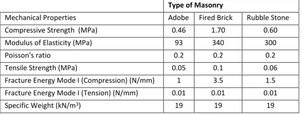
compressive strength and the tensile strength is calculated as 0.06 MPa. The material properties input into the numerical model for different types of masonry are tabulated in Table 4.
Table 4: Material properties of different types of masonry input into the numerical model. Type of Masonry
Mechanical Properties Adobe Fired Brick Rubble Stone Compressive Strength (MPa) 0.46 1.70 0.60 Modulus of Elasticity (MPa) 93 340 300 Poisson's ratio 0.2 0.2 0.2 Tensile Strength (MPa) 0.05 0.1 0.06 Fracture Energy Mode I (Compression) (N/mm) 1 3.5 1.5 Fracture Energy Mode I (Tension) (N/mm) 0.01 0.01 0.01 Specific Weight (kN/m3) 19 19 19
3.4.4 Timber
Timber elements are also present in the structural system of the Ica Cathedral being modelled in two locations: timber framed structure of the bell tower structure and in timber lintels assumed to be present above the openings. From the experimental campaign and inspection of the structure carried out by PUCP, it is known that the timber framed structure of the bell towers is constructed of Huarango timber species. The material properties obtained characterising the same are tabulated in Table 5
Additionally the timber lintels also assumed to be constructed of Huarango timber species, since it is the species with the highest Young's modulus and these were inserted to prevent the excessive concentration of stresses near the openings since no damages were seen there.