Effect of Weld Parameters on Residual Stress, Hardness and Microstructure of Dissimilar
AA2024-T3 and AA7475-T761 Friction Stir Welded Joints
Sergio Delijaicova* , Patricia Aparecida de Oliveira Silvaa , Hugo Borelli Resendeb,
Mario Henrique Fernandes Batalhab
Received: February 20, 2018; Revised: June 02, 2018; Accepted: August 04, 2018
This study presents the effect of the welding parameters variation on the results of forces, temperature, residual stresses and Vickers micro hardness of dissimilar butt joints of AA2024-T3 and AA7475-T761 welded by friction stir welding (FSW). The tool rotational speed, feed rate and tool tilt angle were investigated using the Design of Experiments method. The obtained results of penetration force, temperature in the weld zone compared with the microscopic analysis of the microstructure showed that it is necessary a minimum amount of force and heat input to obtain a defect free weld zone. It was also notable that, friction stir welding has a wide stability range of its most significant parameters - rotational speed and feed rate - which grantee this minimum condition. Micro hardness’ profiles showed the effect of the grain size refinement towards the thermo-mechanically affected zone as well as, the effect of recrystallization inside the nugget. Residual stresses’ profiles showed a tensile stress peak at the shoulder contact area due the pressure with the base material on thermo-mechanically affected zone and the stress relief effect caused by high temperatures in the nugget resulting in a decrease in residual stress value. The most significant variables for residual stress results were rotational speed of the tool and welding feed rate, once their interaction rule the heat input in the weld zone.
Keywords: Friction Stir Welding, Aluminum, Dissimilar Materials, Residual Stress.
*e-mail: [email protected]
1. Introduction
Friction Stir Welding (FSW) is a solid-state welding process developed by The Welding Institute (TWI) in 1991 in the United Kingdom, which has been extensively studied due to its applicability. It is used especially in low melting point alloys such as Al, Mg and Cu1-3 and heat treatable
Aluminum alloys, such as the 2XXX and 7XXX series, as welding them by conventional techniques generates loss of mechanical properties, as well as formation of solidification cracks, brittle fracture and oxide formation due to the high temperatures reached in conventional welding processes4.
Such alloys are widely used in aeronautic applications due to their high resistance combined with low density, as well as good fatigue resistance properties, as in the case of the 2XXX series5-6.
Although, heat treatable Aluminum alloys may be successfully joined by employing low heat input arc welding, such as pulse arch welding or cold metal arch welding or even laser or electron beam welding, the strength loss in the heat affected zone (HAZ) cannot be avoided by those methods. Age-hardened alloys, such as A2XXX and A7XXX series can even be welded by gas metal arch welding with cold metal transfer or high-power density fusion techniques,
but it requires a low and continuous heat input and adequate filler must be used7.
FSW is a welding technique based on the rotational movement between a tool and the base material, which leads to the formation of a plasticized region by the friction generated heating. The feed rate of the tool and the relative rotational movement between the tool and the base material allow the plasticized material to consolidate, guaranteeing the execution of the weld8.
The heat generated by the friction between the tool shoulder and the base material promotes intense local heating that does not melt the parts but assists in the plastic deformation of the material around the tool. The stirring tool moves along the workpiece by mixing and transferring the softened material around them to form the joint. The tool shoulder presses the plasticized material and prevents it from escaping through the surface. Thus, the materials is mechanically mixed in a severe deformation condition during the process9-12.
Comparing the efficiency between FSW and riveted joints when performing tensile and compression tests on two identical panels formed by AA7075-T6 and AA2024-T3, the following advantages were observed in the execution of joints by FSW13:
a. Regarding the resistance limits: there was a ten percent increase in the tensile strength; there was an increase of forty-one percent in the total elongation,
aCentro Universitário da Fundação Educacional Inaciana - FEI, Departamento de Engenharia
Mecânica, São Bernardo do Campo, SP, Brasil
bInstitutos de Pesquisas Tecnológicas - IPT, Laboratório de Estruturas Leves, São José dos Campos, SP,
b. As for the compression: the supported loads were equivalent to the riveted panels; FSW-welded panels continue to deform after failure, while rivets failed catastrophically;
c. Shear: there was an eight percent increase in shear stress compared to rivets; FSW-welded panels were able to dissipate deformation energy less abruptly than the rivet-joined panels, maintaining load bearing while subjected to damage to the stringers. FSW has presented better fatigue behavior than mechanical riveting and it causes a decrease in fatigue crack growth due to the presence of beneficial residual stresses in the weld zone14-15. Regarding the strength of the joint, the performances
of welded joints by FSW and mechanically riveted aluminum plates 2024 T3 concluded that the maximum tensile strength in FSW greater than the one achieved with the riveted joint, has confirmed the effectiveness of this type of solid state welding as an effective alternative to riveting16.
From the metallurgical perspective, FSW process generates low distortion in the base material, assures dimensional stability of the parts, preserves the alloy’s elements of the base material, maintains its mechanical properties, generates a recrystallized microstructure of fine grains, prevents cracking by solidification, as well as allows the welding of all types of Aluminum alloys. It is an environmentally friendly process, as it is performed with no gases, consumables and fumes, in addition to replacing singular fixation elements, generating weight reduction and consequent fuel economy in aeronautical and automotive applications17-18.
The mechanical and microstructural analysis of the joint of AA 2024-T3 and AA 7075-T6 sheets by FSW, shows:
a. There is a recrystallized structure of grains remarkably finer than the grains of the original base material which are mechanically transformed into a refined structure of equiaxed grains at the center of the weld; b. The tensile strength limit of the joint is close to the
limit of the least resistant base material; c. There is a decrease in the fatigue strength limit; d. The tensile fracture surface is characterized by a
ductile mechanism 19.
The welding parameters have great influence in the results of mechanical and microstructural properties as they directly affect the attainment of a defect free and with desirable penetration weld joint. The properties of the base materials and welding tools dictate the choice of parameters. It was found that materials with low strength limits and hardness and high ductility are easier to weld by FSW. The limits of flow, ductility and hardness of Aluminum alloys play a major role in the quality of the weld joint and empirical relationships can be established to determine if the welding parameters guarantee defect free joints according to the properties of the base material20.
Parameters such as tool rotation, feed rate along the joint, vertical force on the tool, tool tilt angle, tool penetration in
the joint and tool geometry are independent variables that can be controlled during the process21.
Low feed rates provide a higher heat generation per unit of length of the weld, since the tool stays longer in the region, on the other hand, high speeds lead to lower heat generation22.
The rotational speed of the tool is a parameter directly linked to the generation of heat and temperature increase, due to the friction of the tool with the base material, and is responsible for mixing the material around the pin, causing the material to flow from the front to the back of the tool23.
The vertical force or penetration force (Fp) is a parameter that directly influences the heat input of the process and the formation of weld joint defects. It must be treated as an independent variable and so it is necessary the equipment to have an active control for the force application, as its oscillation leads to a loss of quality of the joint, formation of surface defects, such as burrs, and reduction of cross section of the welded joint24.
The tilt angle of the tool represents the angle between the tool axis and the axis of the machine main axle. It assists the movement of the material from the front to the back of the pin and in the consolidation of the plasticized material, due to the higher pressure in this region. The penetration of the tool represents the depth that the tool shoulder penetrates into the material to weld, which depends on the thickness of the plate, the geometry and length of the pin, as well as the tilt angle adopted. This parameter defines the pressure exerted to the material during the welding process. If the pin is excessively long, the tool shoulder has little contact with the sheet to weld, which reduces the welding temperature and reduces the pressure exerted by the back of the shoulder to the plate, resulting in defective welding25.
It is the rotary tool that heats the material by a combination of friction and plastic deformation work at temperatures close to, but below the melting point of the base materials. The plastic flow of the materials during welding is complex and depends on the design of the tool, where most of the plastic deformation occurs by shearing the material in its surroundings26. In order to improve the flow of the material
in the process it is possible to develop several types of pins
such as, threaded and tapered27.
The joints obtained by FSW usually have better suface quality and weld profile than those performed by conventional welding techniques, but they may also have defects such as, surface irregularity caused by unbalenced motion of the tool, kissing-bond caused by insufficient pressure during the weld. There may also be excess of flash due to surface overheat, formation of channel-like void in the stir zone near the bottom of the weld due to the flow o plasticized material from the stir zone beneath the shoulder28.
the most resistant material at the retreating side to smooth the initial material stirring29.
In view of the great applicability potential of the FSW, in addition to its use in high-demand structural applications, the present study performs an analysis of the relationship between the welding parameters and the results of residual stresses, micro hardness and temperatures and its objective is divided in two steps:
a. Correlation of the results of penetration force, axial force, torque and temperature with the variable parameters of the process such as, rotational speed, welding feed rate and tool tilt angle, searching for the most significant parameters of the process; b. Analysis of transverse and longitudinal residual
stresses, micro hardness, microstructure of welded joints and their correlations with temperature during welding.
2. Materials and Methods
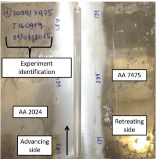
Dissimilar butt welds were performed by the FSW process to join Aluminum sheets of AA 2024-T3 and AA 7475-T761 (200 x 80 x 1.6 mm), according to chemical compositions given by the Table 1. The scheme of identification of the sheets can be seen in the Figure 1. The choice of these alloys and treatments was due to the need to meet a demand from an aeronautical industry.
In order to smooth material stirring from the advance to retreating side, the most resistant alloy, AA 7475-T761, was placed at the retreating side.
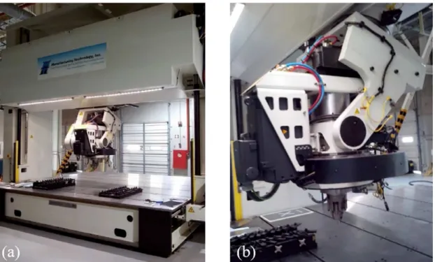
The equipment used for welding was a CNC dedicated machine to the FSW process. (Figure 2) with 5 axes of movement, 30kW power in the spindle and maximum axial force of 80kN. The instrumented head can measure forces in three directions, torques and rotations. The Light Structures Laboratory (LEL) of the Institute provided the machine for Technological Research (IPT) of São Paulo.
A Central Composite Design with 8 full factorial points, 6 stellar points, 2 central points and two replicates was
executed according to Table 2. The independent variables chosen were the tool rotational speed (n), the feed rate (f) and the tilt angle (a). The Analysis of Variance (ANOVA) was performed with the assistance of Statistica software.
The tempered AISI H13 tool steel used was machined with smooth concave shoulder of 8 mm diameter and conical pin with bottom diameter of 2.4 mm, upper diameter of 2.8 mm and height of 1.5 mm. A high temperature quenching and tempering with hardness of 46 HRC followed by nitriding treatment with a layer of 0.10 mm was executed to ensure the least possible wear of the tool. During welding, the tool was replaced by another one whenever a slight wear was observed.
In order to measure the temperature in the welding zone during the process, an infrared camera was used, which was positioned parallel to the tool, providing a frontal view of the process and the thermally affected zone. For the statistical analysis, the mean value of temperature after the stability of the process occurred was calculated.
The transverse residual stresses (direction perpendicular to the weld line) was measured using an X-ray diffractometer. The X-ray tube of Cr and Vanadium filter, and scanning parameters were used according to Table 3.
A transverse residual stress profile was obtained on the surface of the plates by measuring 13 points, the first point at the center of the weld bead (point 0), 6 points at the advancing side and 6 points at the retreating side. The points were distanced by 2 mm apart according to Figure 3.
In addition to the 13 points, a total measurement of 2 plates was made to verify the trend of the transverse residual stress behavior along the plate.
The residual stress in the longitudinal direction of the plates (line weld direction), was measured using the Hole
Table 1. Chemical compositions of AA2024T3 and AA7475-T761 alloys.
Element Chemical composition (wt%)
AA 2024-T3 AA 7475-T761
Cr 0,1 (max.) 0,18 – 0,25
Cu 3,8 – 4,9 1,2 – 1,9
Fe 0,5 (max.) 0,12 (max.)
Mg 1,2 – 1,8 1,9 – 2,6
Mn 0,3 – 0,9 0,06 (máx.)
Si 0,5 (max.) 0,1 (max.)
Ti 0,15 (max.) 0,06 (max.)
Zn 0,25 (max.) 5,6 – 6,2
Others 0,15 0,15
Figure 2. FSW machine provided by LEL (a) used to weld the samples and detail of its instrumented head (b).
Table 2. Independent variables
Welding parameters Symbol Units Levels
-1 0 1
Tool rotational
speed N rpm 1300 1450 1600
Welding feed rate f mm/min 40 65 90
Tool tilt angle a º 1 2 3
Table 3. X-ray diffractometer scanning parameters. Equipment parameters for residual stress measurement
ψ1 [°] 0
ψ2 [°] 15
ψ3 [°] 30
ψ4 [°] 45
Scan method - Countinous
Stress method - Psi 0 constant
Scan axis - 2Theta
Scan range [°] 137 - 142
Step angle [°] 0,1
Scan speed [°/min] 5
Voltage kV 30
Current mA 40
KAA2024 [kg/mm²/°] -17,4
KAA7475 [kg/mm²/°] -18,9
Kstir (central point) [kg/mm²/°] -18,15
Figure 3. Scheme of placement of points for residual stress measurement.
Drilling Method, since the longitudinal capacity of the X-ray diffractometer was not sufficient for the plates dimensions.
hole at the center of the weld line, three holes at advancing side and three holes at the retreating side. The distance between holes was 3 mm.
4. Results and Discussion
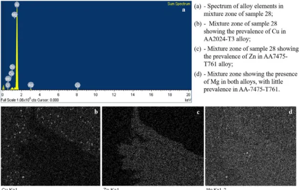
The good performance of the process is observed by the optical microscopy of Figure 5 where it is possible to observe the refinement of the grains towards the TMAZ, which is composed of grains much finer than the HAZ, as well as through Figure 6, obtained by scanning electron microscopy (SEM). It demonstrates the good mixture and absence of defects in the case of a medium value of rotational speed (1450 rpm) and low value of feed rate (40 mm / min), which enables sufficient heat input in the region of the nugget resulting in the good mixture and material flow.
In Figure 6 it is possible to observe the flow of the main alloy elements involved, Cu in the case of AA2024-T3 and Zn in the case of AA7574-T761. In Figure 6-b, the Cu element is highlighted by the lighter color and higher brightness intensity, it represents the prevailing element of AA2024-T3 and it is possible to see a trend of flow of that material towards the retreating side towards the region of the AA7475-T761, whose major alloy element is Zn, highlighted by the brightest area of Figure 6-c.
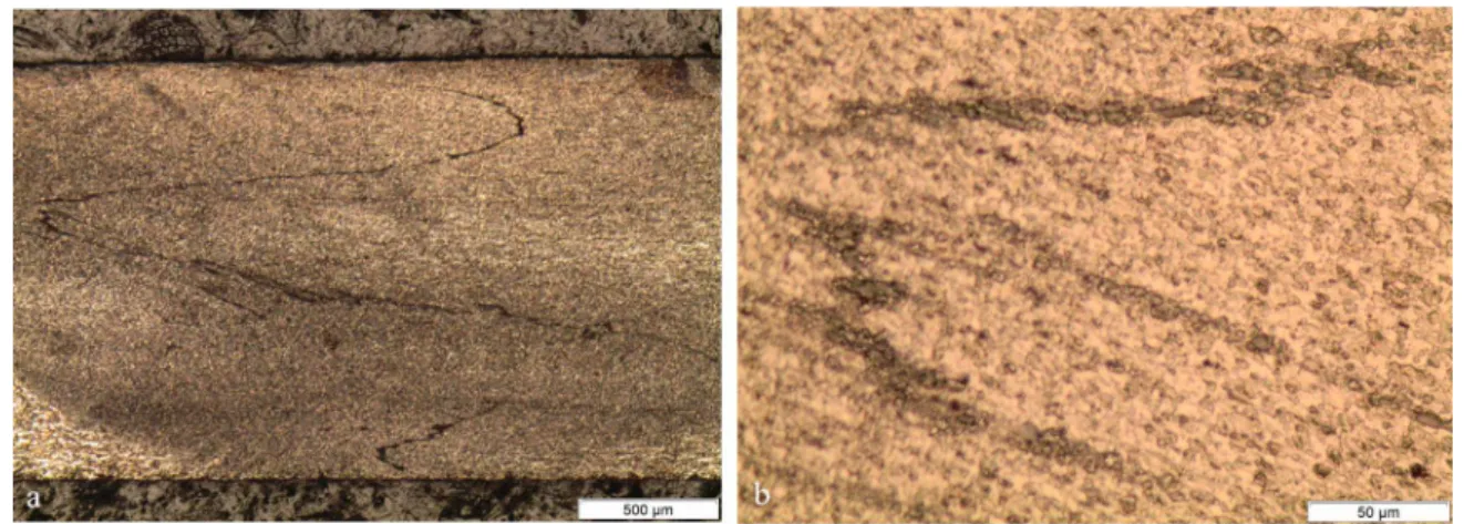
The optical microscopy of sample 17 of Figure 7 revealed the expected structure of the welding zone, where the grains become finer as they reach the nugget of the weld, where there is the greatest plastic deformation and consequently the greatest grain refinement in the weld zone. In Figure 7-a, the workpiece of advance side, AA 2024-T3, in its raw condition, without influence of the welding process, with coarse and non-equiaxed grains is observed. The same is shown at the retreating side, AA 7475-T761, in Figure 7-b.
In Figure 7-c it is possible to visualize the transition between the heat affected zone and the end of thermo mechanically affected zone at advance side, where there is the greatest grain refinement due to severe plastic deformation produced
by the pin work in nugget area. The same transition at the retreating side is shown in Figure 7-d.
In Figure 8-a the weld nugget is shown in the thermo-mechanically affected zone, where it is possible to verify the presence of a defect known as kissing bond, which is characteristic of incomplete bond of the materials in the welded joint. In the case of sample 17, a low value of rotational speed (1360 rpm) was used, which did not provide sufficient heat input to enable the proper mixture of materials.
In Figure 8-b it is possible to observe a magnification of the defect, clarifying the non-mixture of the alloys.
Table 4 shows the results of experimental measurements according to the central composite design. The independent variables of the experiment are rotational speed of the tool (n), welding feed rate (f) and tool tilt angle (a). The dependent variables are penetration force (Fp), torque (Mt), feed force (Ff), temperature (T), hardness (Hv) and residual stresses (RS). The welding feed rate and positioning angle (tilt angle) had less impact on the efforts generated by the welding process, but not secondary. It is expected that the higher the rotational speed of the tool, the lower the resultant efforts are, however, the welding feed rate must guarantee the necessary amount of time at the mixture temperature to enable the materials to soften. When the welding feed rate
Figure 6. Spectrum of alloy elements distribution and mixture zone appearance obtained by SEM.
Figure 8. Weld nugget of sample 17 with kissing bond defect.
variated to higher values, as shown in Table 4, the resultant efforts increased and it demonstrates that the time spent in the mixture temperature was not enough to enable a good welding performance. The most significant consequence of increase in efforts is the wear of the tool.
Table 4 also shows that the larger the tool tilt angles, the greater the efforts for the same values of rotational speed and feed rate. This was expected, and although negatively affecting the wear of the tool, it was necessary for the weld bead to remain homogeneous, as observed visually in the inspection of the welded plates. However, there were burrs in some plates, showing that the penetration force was not high enough to avoid them. The insufficient penetration force resulted from the execution of the experiment with control penetration depth of the tool instead of control of penetration force. This lack of control, caused instability issues during the execution of the weld due to high feed rates that did not allow the tool to spend a the minimum time required at the same position to enable the materials to fully soften.
Figures 9 and 10 show the fitted response surfaces of penetration force (Fp) analysis and demonstrate the stability ranges for rotations between 1350 and 1550 rpm through the full range of welding feed rates and tool tilt angles. It means that, it is possible to choose practically any value - at first approximation - in the variables’ domain of this experiment in order to have a good quality welded joint.
The lowest results of penetration forces are in the central range of rotational speed variation, combined with values of tilt angle of 1.2° up to 2.2°. A low tool penetration resultant force in the plate is not the best condition for the process, since it can compromise the role of the shoulder of pressing the mixture material, preventing it from escaping from the weld bead. In addition to that, it compromises part of the heat generated by friction, consequently not allowing the
joint to reach sufficient temperature for the proper occurrence of the mixture.
By evaluating the relationship between rotational speed (n) and feed rate (f) variables in the surface diagram of Figure 10, it is possible to infer that the increase in rotational speed tends to decrease the penetration force due to the increase in heat generated by friction between the shoulder and the base material, that leads to an easier material softening and consequent improvement in tool linear movement. On the other hand, when high rotational speed values are combined with high feed rates, this effect does not happen due to the decrease in time spent by the tool at the same spot, it difficult the heat generation and demands higher efforts for the tool to move linearly. The worst condition occurs when combining high feed rates and low rotational speeds, which leads to a low heat input in the welding region.
In Figure 11, it is possible to observe the tunneling defect due to high feed rate (90 mm/min), which did not allow the rotational speed to generate the necessary heat flow for the plasticized material to transfer completely from the advance to the retreating side. Thus, cavities appear in the weld bead and may lead to fatigue fractures.
In Figure 12, as expected, torque is inversely proportional to rotational speed; low rotational speed values require higher torques of the welding machine head. Also in Figure 12, it is possible to infer that the feed rate did not influence the results of torque.
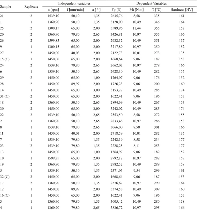
Table 4. Central composite design experimental results of the welded samples.
Sample Replicate Independent variables Dependent Variables
n [rpm] f [mm/min] a [ ° ] Fp [N] Mt [N.m] T [°C] Hardness [HV]
21 2 1539,10 50,10 1,35 2635,76 8,58 335 161
1 1 1360,90 50,10 1,35 3128,00 10,49 346 164
25 2 1300,15 65,00 2,00 3589,96 11,44 355 152
20 2 1360,90 79,80 2,65 3426,81 10,97 355 166
26 2 1599,85 65,00 2,00 2982,12 10,49 351 157
9 1 1300,15 65,00 2,00 3717,89 10,97 350 152
27 2 1450,00 40,03 2,00 2122,73 10,01 273 135
15 (C) 1 1450,00 65,00 2,00 1668,64 9,06 187 153
24 2 1539,10 79,80 2,65 2662,02 10,97 278 166
6 1 1539,10 50,10 2,65 2628,30 10,49 282 155
29 2 1450,00 65,00 1,00 1764,07 9,06 176 152
28 2 1450,00 89,97 2,00 1726,23 9,06 200 160
14 1 1450,00 65,00 3,00 3153,27 10,49 285 174
31 (C) 2 1450,00 65,00 2,00 1622,41 9,06 196 153
18 2 1360,90 50,10 2,65 2894,69 10,49 267 153
30 2 1450,00 65,00 3,00 3242,02 10,49 285 174
22 2 1539,10 50,10 2,65 2553,50 8,58 272 155
2 1 1360,90 50,10 2,65 2833,48 10,97 286 153
8 1 1539,10 79,80 2,65 3066,00 8,58 301 166
11 1 1450,00 40,03 2,00 2718,59 10,01 282 135
7 1 1539,10 79,80 1,35 2242,19 8,58 234 177
23 2 1539,10 79,80 1,35 2228,25 8,11 253 177
13 1 1450,00 65,00 1,00 1564,97 9,06 182 152
10 1 1599,85 65,00 2,00 2792,12 10,97 282 157
19 2 1360,90 79,80 1,35 2982,52 10,49 289 158
5 1 1539,10 50,10 1,35 2571,05 9,54 299 161
32 (C) 2 1450,00 65,00 2,00 1668,64 9,06 187 153
17 2 1360,90 50,10 1,35 2576,67 10,97 290 164
12 1 1450,00 89,97 2,00 3374,58 10,49 309 160
16 (C) 1 1450,00 65,00 2,00 1622,41 9,06 196 153
3 1 1360,90 79,80 1,35 3005,42 10,49 280 158
4 1 1360,90 79,80 2,65 3836,72 10,97 295 166
On the other hand, when working in a fixed rotational speed and increasing the tilt angle of the tool, there is an increase in temperature, since, the increase of tilt angle leads to an increase in penetration of the tool shoulder in the weld joint. It increases the area of friction between the shoulder and the base material and consequently leads to greater heating of the zone.
The Vickers micro hardness profile of Figure 14 for the welding conditions of samples 17 and 22 presented a profile in the shape of the letter W. In this profile, hardness decreased in the transition from the base material to the HAZ due to the aging of precipitates on AA 7475-T761 alloy and solubilization on AA2024-T3. It happens because, the average temperatures
reached were 272 °C in sample 17 and 290 °C in sample 22, which is higher than the aging temperature of 177 °C for AA 7475-T761 alloy and 256 °C solution temperature for AA 2024-T3 alloy. It was also observed the increase of the hardness when entering the TMAZ, since in this region the plastic deformation imposed by the shoulder, that initiates the grain refinement, begins and the temperature reached is not enough for recrystallization.
Figure 9. Fitted response surface diagram of penetration forces results (Fp) for n and a variables.
Figure 10. Fitted response surface diagram of penetration forces results (Fp) for n and f variables.
Figure 11. Image of the stir zone of sample 28 acquired by electronic scanning microscopy.
Figure 12. Fitted response surface diagram of torque results (Mt) for n and f variables.
other regions, since the severe plastic deformation caused by the pin leads to a very fine and equiaxed grain structure.
In Figure 14, when comparing the hardness results for plates 17 and 22, welded at the same feed rate of 50.1 mm/ min, it is possible to observe that the increase in rotational speed led to a lower hardness result due to the higher contribution of heat that leads to higher temperatures in the affected zones. This phenomenon increases the effects of recrystallization and dissolution of precipitates.
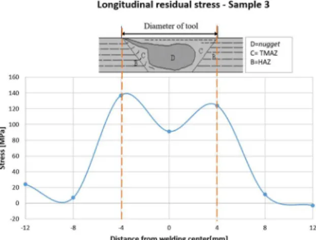
The phenomenon of residual stress can occur due to two factors: the mechanical deformation factor and the temperature gradient factor. The mechanical work of deformation in FSW occurs in the plastic regime of the material and therefore its effect on the residual stress is zero. However, full and homogeneous plasticizing of materials in the mixture zone cannot be guaranteed, which leads to compressive values of mechanical residual stress at low levels. In the mixture zone, the temperature reached levels that favored the phenomenon of recrystallization and thus, the residual stress portion due to thermal gradient is high and tensile. The expected algebraic sum of residual stresses is tensile and is shown in Figure 15 and Figure 16, both for the longitudinal residual stresses and the transverse residual stresses.
This research demonstrated that the most significant parameters in results of residual stresses were the rotational speed, the welding feed rated and their interactions. The effect of increasing rotational speed and decreasing welding feed rate was the reduction of the magnitude of the residual longitudinal tension. This is associated with the increase of the heat introduced.
The region of the mixture, which contains the circular region of the tool pin (2.4 mm), has an increasing hardness profile due to the mechanical stretching work (metals are mixed and centrifugally forced to leave the region) - figure 14 - which leads to an increase in both longitudinal and transverse residual stresses observed in Figure 15 and Figure 16. Outside the mixture region up to the limits of the heat affected zone, which is limited approximately by the diameter of the tool shoulder (8 mm), the lower temperature leads to more mechanical work and less heat input, resulting in a tensile residual stress higher than the value found in mixture zone. Outside the areas affected by welding is the
Figure 14. Micro hardness profile of samples 17 and 22.
Figure 15. Longitudinal Residual Stress profile for sample 3.
Figure 16. Transversal Residual Stress profile for sample 22.
base material with compressive residual stress due to the mechanical work of sheets lamination. The result shown in Figure 15 and Figure 16 also assured that the values of residual stresses on the less hard material side, AA2024, were lower than those obtained on the harder material side, AA7475.
5. Conclusions
This work aimed to correlate the results of stress and temperature with the parameters of the welding process and to obtain the most significant parameters. In addition, another objective was the analysis of microstructure, residual stresses and micro hardness correlating them with temperature. The main conclusions were:
a. The most significant parameters of the process were the rotational speed (n) and welding feed rate (f), since they rule the heat and flow of the material; b. To obtain the mixture without tunneling defect it
is necessary to take the joint to high temperatures and for this purpose, it is necessary to work in high rotational speed and low feed rate.
and consequently the generation of heat by friction is compromised;
d. In the nugget, the hardness suffers a small decrease due to the high temperature of the region that leads to the recrystallization of the grains;
e. The increase of longitudinal and transverse residual stresses starts at the TMAZ due to shoulder pressure at the joint;
f. Maximum tensile stresses were slightly higher on the retreating side, where the highest mechanical strength alloy (AA7475-T761) was positioned.
6. References
1. Liu X, Lan S, Ni J. Analysis of process parameters effects on friction stir welding of dissimilar aluminum alloy to advanced high strength steel. Materials &Design. 2014;59:50-62. 2. Almomani M, Hassan AM, Qasim T, Ghaithan A. Effect of
process parameters on corrosion rate of friction stir welded aluminium SiC-Gr hybrid composites. Corrosion Engineering, Science and Technology. 2013;48(5):346-353.
3. Li B, Zhang Z, Shen Y, Hu W, Luo L. Dissimilar friction stir welding of Ti-6Al-4V alloy and aluminum alloy employing a modified butt joint configuration: Influences of process variables on the weld interfaces and tensile properties. Materials & Design. 2014;53:838-848.
4. Mathers G. The Welding of Aluminium and Its Alloys. Sawston: Woodhead Publishing; 2002.
5. Aval HJ, Serajzadeh S, Kokabi AH. Evolution of microstructures and mechanical properties in similar and dissimilar friction stir welding of AA5086 and AA6061. Materials Science and Engineering: A. 2011;528(28):8071-8083.
6. Shtrikman MM. Current state and development of friction stir welding Part 3. Industrial application of friction stir welding. Welding International. 2008;22(11):806-815.
7. Çam G, Ipekoglu G. Recent developments in joining of aluminum alloys. The International Journal of Advanced Manufacturing Technology. 2017;91(5-8):1851-1866.
8. Thomas WM, Nicholas ED, Needham JC, Murch MG, Temple-Smith P, Dawes CJ, inventor; The Welding Institute, assignee. Friction Stir Welding. United States patent US 5460317A. 1991 Dec 6.
9. Rhodes CG, Mahoney MW, Bingel WH, Spurling RA, Bampton CC. Effects of friction stir welding on microstructure of 7075 aluminum. Scripta Materialia. 1997;36(1):69-75.
10. Liu G, Murr LE, Niou CS, McClure JC, Vega FR. Microstructural aspects of the friction-stir welding of 6061-T6 aluminum. Scripta Materialia. 1997;37(3):355-361.
11. Jata KV, Semiatin SL. Continuous Dynamic recrystallization during friction stir welding of high strength aluminum alloys. Scripta Materialia. 2000;43(8):743-749.
12. Benavides S, Li Y, Murr LE, Brown D, McClure J. Low-temperature friction-stir welding of 2024 aluminum. Scripta Materialia. 1998;41(8):809-815.
13. Widener C. Evaluation of Friction Stir Weld Process and Properties for Aircraft Application. JAMS (Internet). Washington: JAMS; 2010. Available from: https://depts.washington.edu/amtas/ events/jams_08/16.Widener.pdf . Access in: 28/05/2018.
14. Fratini L, Pasta S, Reynolds AP. Fatigue crack growth in 2024-T351 friction stir welded joints: Longitudinal residual stress and microstructural effects. International Journal of Fatigue. 2009;31(3):495-500.
15. Lemmen HJK, Alderliesten RC, Benedictus R. Fatigue initiation behaviour throughout friction stir welded joints in AA2024-T3. International Journal of Fatigue. 2010;32(12):1928-1936.
16. Lertora E. Comparison of AA 2024 T3 friction stir welded and riveted overlap joints with the addition of a pressurization test. Materials & Design. 2013;49:259-266.
17. Verma BB, Atkinson JD, Kumar M. Study of fatigue behaviour of 7475 aluminium alloy. Bulletin of Materials Science. 2001;24(2):231-236.
18. Mishra R, Mahoney W, eds. Friction Stir Welding and Processing. Materials Park: ASM International; 2007.
19. Cavaliere P, Nobile R, Panella FW, Squillace A. Mechanical and microstructural behaviour of 2024-7075 aluminium alloy sheets joined by friction stir welding. International Journal of Machine Tools and Manufacture. 2006;46(6):588-594.
20. Balasubramanian V. Relationship between base metal properties and friction stir welding process parameters. Materials Science and Engineering: A. 2008;480(1-2):397-403.
21. Nadan R, DebRoy T, Bhadeshia HKDH. Recent advances in friction-stir welding - Process, weldment structure and properties. Progress in Materials Science. 2008;53(6):980-1023.
22. Oliviecki NJ, Beskow AB. Analysis of the Parameters of Friction Welding Process of an Aluminum Alloy. Perspectiva. 2013;37(138):15-29.
23. Mishra RS, Ma ZY. Friction Stir Welding and Processing. Materials Science and Engineering: R. 2005;50:1-78. 24. Cruz MF. Desenvolvimento dos parâmetros de Friction Stir
Welding - FSW, aplicado na junção de topo de chapas finas de alumínio de alta resistência. [Dissertation]. São José dos Campos: Instituto Tecnológico de Aeronáutica; 2009.
25. Zhu XK, Chao YJ. Numerical simulation of transient temperature and residual stress in friction stir welding of 304L stainless steel. Journal of Materials Processing Technology. 2004;146(2):263-272.
26. Burford P, Gimenez Britos E, Boldsaikhan E, Brown J. Evaluation of Friction Stir Weld Process and Properties for Aerospace Application: e-NDE for Friction Stir Processes. In: 6th Annual Technical Review Meeting; 2010 May 19-20; Washington, DC, USA.
27. Podržaj P, Jerman B, Klobčar D. Welding defects at friction stir welding. Metalurgija. 2015;54(2):387-389.
28. Çam G, Mıstıkoğlu S. Recent Developments in Friction Stir Welding of Al-Alloys. Journal of Materials Engineering and Performance. 2014;23(6):1936-1953.