MSc in Paleontology
Evolution of Diplodocid Sauropod
Dinosaurs with Emphasis
on
Specimens from Howe Ranch, Wyoming
(USA)
Dissertação para obtenção do Grau de Doutor em Geologia, especialidade de Paleontologia
Orientador: Prof. Octávio Mateus, CICEGe-FCT,
Universidade Nova de Lisboa
Júri:
Presidente: Prof. Doutora Maria Paula Pires dos Santos Diogo
Arguentes: Prof. Doutor Paul Upchurch Prof. Doutor Louis Jacobs
Vogais: Prof. Doutor Rogério Rocha Prof. Doutor João Pais
Doutor Fidel Torcida Fernández-Baldor Prof. Doutor Octávio Mateus
Evolution of Diplodocid Sauropod Dinosaurs
Emanuel Tschopp
2013
B
A
D
I
Emanuel Tschopp
MSc in Paleontology
Evolution of Diplodocid Sauropod
Dinosaurs with Emphasis on Specimens
from Howe Ranch, Wyoming (USA)
Dissertação para obtenção do Grau de Doutor em Geologia, especialidade de Paleontologia
Orientador: Prof. Octávio Mateus, CICEGe-FCT, Universidade
Nova de Lisboa
Júri:
Presidente: Prof. Doutora Maria Paula Pires dos Santos Diogo
Arguentes: Prof. Doutor Paul Upchurch Prof. Doutor Louis Jacobs Vogais: Prof. Doutor Rogério Rocha
Prof. Doutor João Pais
Doutor Fidel Torcida Fernández-Baldor Prof. Doutor Octávio Mateus
II
Copyright capítulos 1, 4.3-4.4, 5-7: Emanuel Tschopp, Faculdade de Ciências e Tecnologia – UNL, and Universidade Nova de Lisboa
A Faculdade de Ciências e Tecnologia e a Universidade Nova de Lisboa tém o direito, perpétuo e sem limites geográficos, de arquivar e publicar esta dissertação através de exemplares impressos reproduzidos em papel ou de forma digital, ou por qualquer outro meio conhecido ou que venha a ser inventado, e de a divulgar atraves de repositôrios cientificos e de admitir a sua côpia e distnibuiçao com objectivos educacionais ou de investigacao, não comerciais, desde que seja dado crédito ao autor e editor.
III
dedicata a te
per la tua pazienza infinita
per il tuo sostegno e supporto straordinario
per il tuo amore
IV
Acknowledgment
A Ph.D. thesis cannot be undertaken without a supervisor, so my first, big “thank you” goes to Octávio Mateus, who was a thoughtful and understanding mentor. He found the perfect equilibrium between tight guidance and leaving room for my own decisions, and thereby easily managed to keep my interest in science very strong.
Further thanks go to the remaining members of the doctoral committee, which are Martin Sander (Bonn, Germany), João Pais, Rogerio Rocha (both CICEGe), and Louis Jacobs (Dallas, USA). They were there when I needed further advice or help with administrative things.
Besides them, most importantly, I want to thank Köbi Siber (or Kirby for the English speaking readers), and anybody else from the Sauriermuseum Aathal (Switzerland), not only for the possibility to study material under their care during my Ph.D. thesis, but especially for their continuing support and inspiration during my entire (yet still short) scientific career. I obtained my first preparation skills in the museum, the first professional paleontological excavation I took part was at the Howe Ranch, I held my first scientific presentation at the Stegosaur Symposium in Aathal in 2009, and my first scientific paper was a result from the studies done for the symposium in material from the Sauriermuseum. I was allowed to photograph, laser scan, drill, CT scan, take samples for SEM, and museum staff was always available for help. Through the museum, and especially thanks to Köbi, I got to know many important paleontologists on my way, among which was also my present supervisor Octávio Mateus. Finally, the Sauriermuseum also provided financial support for some of my studies, or for travels to field work or conferences, which I greatly acknowledge.
From the Sauriermuseum staff I want to thank in particular, and specifically for the work done for my Ph.D. thesis: Esther Premru for the outstanding work during the preparation of the bones and the drawing of the quarry map of the holotype specimen of Kaatedocus siberi SMA 0004, Ben Pabst for the stunning reconstruction of its skull, and Martin Kistler and Ben Pabst for the help with the dismantling of SMA 0004 for the structured light scanning. Martin Kistler and his team also helped a lot with opening boxes for the study of SMA 0011. Preparation of that specimen was led by Yoli Siber, together with Maya Siber, Esther Wolfensberger, and myself back in 2001 and 2002. Specimen SMA 0087 is being prepared by Christina Egli and Yoli Siber, quarry maps of both SMA 0011 and 0087 were drawn by Esther Premru.
I furthermore want to thank the staff of the Museu da Lourinhã for their companionship, and the technical support during my stay in Lourinhã. Particular thanks go to the entire Mateus family for hospitality, and to João Russo and Simão Mateus for their help with the thesis formatting and printing.
I highly appreciated the work with my co-authors and collaborators for some of the papers published during the time of my Ph.D.: Gordon Dzemski (Flensburg, Germany) introduced me to 3D scanning and reproduction, which lead to two articles (Tschopp and Dzemski, 2012; Tschopp et al., 2013). João Russo (CICEGe) contributed the part on deforming a Dodo cervical vertebra to the retrodeformation paper, which is part of the present thesis (Tschopp et al., 2013). Inspiring artistic collaborations were made with Davide Bonadonna (Milan, Italy), Andrea Pirondini (Bologna, Italy), and Simão Mateus (ML). Bonadonna provided the highly accurate skull life reconstruction of Kaatedocus siberi for the description (Tschopp and Mateus, 2012b: fig. 12), and with an extended version of this life reconstruction, arranged as a poster by Pirondini, he won the 2013 Lanzendorf PaleoArt Award of the Society of Vertebrate Paleontology in the category Scientific Illustration. A second piece with Kaatedocus siberi in his environment at the Howe Quarry locality was used as background for the new permanent exhibit around the holotype specimen at SMA, and was awarded the 2013 Lanzendorf PaleoArt Award of SVP in the category 2D Illustration. Simão Mateus created the beautiful reconstruction of the skull of Galeamopus shellensis.
V
Regina Fechner (Univ. Bochum, Germany) on sauropodomorph gastralia and sternal ribs, and for her comments on a first draft of the clavicles manuscript. Ricardo Araújo and Jasmina Hugi (Winterthur, Switzerland) were of great help with finding literature on the embryological development of the various chest bones in reptiles, birds and mammals. Emanuele Minari (Turin, Italy) translated the description of the clavicle of Datousaurus in Dong and Tang (1984). Octávio Mateus, Christophe Hendrickx (CICEGe), Steve Brusatte (Univ. of Edinbourgh), Jay Nair (Univ. of Queensland), and Mike Taylor (Univ. of Bristol) reviewed an earlier version of portions of the dissertation. Ioannis Michelis shared information concerning Barosaurus and the Howe Quarry material. Remo Forster (Zürich, Switzerland) helped with some figures of the specimen SMA 0087. Lara Couldwell (ML), Holly Barden (Univ. of Manchester), Steve Brusatte, Jay Nair, and Mike Taylor provided corrections for the English. I also want to thank the editorial staffs of the Journal of Paleontological Techniques, the Journal of Systematic Palaeontology, the Journal of Anatomy, and Palaeontologia Electronica for their help, as well as four anonymous reviewers for thoughtful and detailed reviews of the published papers.
A specimen-based phylogenetic analysis as performed herein is highly dependent on personal observations of the specimens included. Although it was not possible to see all of them, many collection visits were possible thanks to the help and hospitality from the following people: Kate Wellspring (AC), Carl Mehling, Mark Norell, and Alana Gishlick (AMNH), Ted Daeschler and Ned Gilmore (ANS), Amy Henrici, Matthew Lamanna, and Dan Pickering (CM), Rafael Royo-Torres and Edoardo Espilez (CPT), Daniela Schwarz-Wings (MB.R.), Virginia Tidwell and Logan Ivy (DMNS), David Temple (HMNS), Margarita Belinchón (MCNV), Paul Barrett and Sandra Chapman (NHMUK), Matt Carrano and Mike Brett-Surman (USNM), Ralf Kosma, Achim Ritter, and Ulrich Joger (SNHM), Bill Wahl and Malcolm Bedell (WDC), and Dan Brinkman and Marilyn Fox (YPM). Several people shared numerous pictures of specimens I was not able to see myself: Christophe Hendrickx, Carl Mehling, Dave Lovelace (Univ. of Wisconsin), Henry Galiano (Dinosauria International), Heiner Mallison (MB.R.), José Carballido (MPEF), Jean Le Loeuff (Esperaza, France), Jay Nair, John Whitlock, Kelli Trujillo (Univ. of Wyoming), Mattia Baiano (Inst. Cat. Pal, Barcelona), Mike Brett-Surman, Matt Wedel (West. Univ. of Health Sciences, Pomona), Nils Knötschke (Dinopark Münchehagen), Octávio Mateus, Phil Mannion, Pong Suteethorn (Univ. of Mahasarakham, Thailand), Regina Fechner, Ralf Kosma, Takehito Ikejiri (Univ. of Alabama), Virginia Tidwell, William Gearty (YPM), and William Simpson (FMNH).
I thank the Willy Hennig Society for making the phylogeny software TNT freely accessible, and Andrea Cau (Museo Geologico “Cappellini”, Bologna), Jay Nair, and especially José Carballido for invaluable help with phylogenetic techniques.
This study would not have been possible without the financial support throughout my Ph.D. through the doctoral fellowship from the Fundação para a Ciência e a Tecnologia of the Ministério de Educação e Ciência, Portugal (SFRH / BD / 66209 / 2009), under which I also received additional travel subsidies for my stay at South. Methodist Univ. Many thanks go to the Jurassic Foundation for the funding of a project of 3D digitalization and the study of serial variation in sauropod cervical and caudal vertebrae. Travel subsidies were kindly provided by the following institutions: European Science Foundation (a short visit grant for a histology course at Univ. of Bonn, Germany), Jackson School of Geosciences (for the attendance and poster presentation at the SVP conference in Pittsburgh, 2010), Synthesys (DE-TAF-1150; for a collection visit at Museum für Naturkunde, Berlin), Fundação Lusoamericana (for a talk at the Romer Prize Session at the SVP conference in Los Angeles, 2013), and the Sauriermuseum Aathal and Siber & Siber (for the participation at excavations in Wyoming, 2010, and the attendance at the SVP conference in Los Angeles, 2013).
VI
Resumo
Os Diplodocidae estão entre os dinossauros saurópodes mais conhecidos. Várias espécies foram descritas no final do século XIX ou início de XX. Desde então, numerosos espécimes outros foram recuperados nos EUA, Tanzânia, Portugal, bem como, possivelmente de Espanha, Inglaterra e Ásia. Até à data, o clado inclui 12 a 15 espécies diferentes, algumas delas com estatuto taxonómico questionável como, por exemplo, 'Diplodocus' hayi ou Dyslocosaurus polyonychius. No entanto, as relações intragenéricas de géneros multi-específicos e icónicos como Apatosaurus e Diplodocus ainda são pouco conhecidos. A maneira de resolver este desafio é uma análise filogenética baseada em espécimes, o que foi feito para Apatosaurus, mas aqui é realizada pela primeira vez para todo o clado Diplodocidae.
Novo material de diferentes localidades e níveis estratigráficos (em Howe Ranch, Shell, Wyoming, EUA) aumenta o conhecimento sobre a evolução dos Diplodocidae. Três novos espécimes são aqui descritos, aumentando consideravelmente o nosso conhecimento da anatomia do grupo. Os novos espécimes (SMA 0004, SMA 0011 e SMA 0087) representam duas, possivelmente três novas espécies de diplodocídeos, e compreendem material ósseo de todas as partes do esqueleto, incluindo dois crânios quase completos, bem como membros anteriores e posteriores bastante completos, o que é geralmente raro em diplodocídeos. Desta forma, os espécimes permitem um aumento consideravel da sobreposição anatómica entre holótipos que amiúde são incompletos, o que permite obter resultados significativos nesta análise filogenética com base em espécimes. Além disso, são identificados os ossos clavícula e interclavícula, sendo este último aqui reportado pela primeira vez em dinossauros. A sua presença parece restrita aos primeiros saurópodes, Flagellicaudata e Macronaria basais, e pode por isso ser um caso de retenção de plesiomorfia, com a perda destes ossos como sinapomorfia dos Titanosauriformes e possivelmente Rebbachisauridae.
Os novos espécimes permitem testar anteriores hipóteses filogenéticas dos diplodocídeos. Com esse objectivo, todos os espécimes-tipo previamente propostos como diplodocídeos foram incluído no estudo, assim como outros espécimes relativamente completos de forma a aumentar a sobreposição anatómica entre eles. Espécimes ulteriormente sugeridos como saurópodes não-diplodocídeos, foram incluídos como grupos externos. A análise filogenética resultante inclui, assim, 76 unidades taxonómicas operacionais, 45 das quais pertencem a Diplodocidae. Cada espécime foi codificado para 477 caracteres morfológicos, o que representa uma das mais extensas análises filogenéticas de dinossauros saurópodes. O cladograma resultante recupera o arranjo clássico das relações filogenéticas dos diplodocídeos.
Foi realisada uma abordagem numérica para reduzir a subjetividade na decisão de separação específica ou genérica, para as espécies que historicamente têm sido incluídas em géneros conhecidos, como Apatosaurus ou Diplodocus, tendo algumas resultado serem genericamente diferente. Desse modo, o famoso género Brontosaurus é ressuscitado, e as evidências sugerem, ainda que também
Elosaurus parvus (anteriormente designados Apatosaurus) ou 'Diplodocus' hayi representam géneros únicos. O estudo aumenta o conhecimento sobre a variação individual, e ajuda a decidir como classificar géneros multi-específicos. Este tipo de análise filogenética baseada em espécimes provou ser uma ferramenta valiosa para validar espécies históricas em saurópodes, e na paleontologia como um todo.
VII
Abstract
Diplodocidae are among the best known sauropod dinosaurs. Several species were described in the late 1800s or early 1900s. Since then, numerous additional specimens were recovered in the USA, Tanzania, Portugal, as well as possibly Spain, England, and Asia. To date, the clade includes about 12 to 15 different species, some of them with questionable taxonomic status (e.g. ‘Diplodocus’ hayi or
Dyslocosaurus polyonychius). However, intrageneric relationships of the multi-species, iconic genera
Apatosaurus and Diplodocus are still poorly known. The way to resolve this issue is a specimen-based phylogenetic analysis, which was done for Apatosaurus, but is here performed for the first time for the entire clade of Diplodocidae.
New material from different localities and stratigraphic levels on the Howe Ranch (Shell, Wyoming, USA) sheds additional light on the evolution of Diplodocidae. Three new specimens are described herein, considerably increasing our knowledge of the anatomy of the group. The new specimens (SMA 0004, SMA 0011, and SMA 0087) represent two, to possibly three new diplodocid species. They preserve material from all parts of the skeleton, including two nearly complete skulls, as well as fairly complete manus and pedes, material which is generally rare in diplodocids. Thereby, they considerably increase anatomical overlap between the sometimes fragmentary holotype specimens of the earlier described diplodocid species, allowing for significant results in a specimen-based phylogenetic analysis. Furthermore, clavicles and interclavicles are identified, the latter for the first time in dinosaurs. Their presence seems restricted to early sauropods, flagellicaudatans, and early Macronaria, and might thus be a retained plesiomorphy, with the loss of these bones being synapomorphic for Titanosauriformes and possibly Rebbachisauridae.
The new material allows to test previous hypotheses of diplodocid phylogeny. In order to do so, any type specimen previously proposed to belong to Diplodocidae was included in the study, as are relatively complete referred specimens, in order to increase the degree of overlapping material. For specimens subsequently suggested to be non-diplodocid sauropods, their hypothesized sister taxa were included as outgroups. The current phylogenetic analysis thus includes 76 operational taxonomic units, 45 of which belong to Diplodocidae. The specimens were scored for 477 morphological characters, representing one of the most extensive phylogenetic analyses done within sauropod dinosaurs.
The resulting cladogram recovers the classical arrangement of diplodocid relationships. Basing on a newly developed numerical approach to reduce subjectivity in the decision of specific or generic separation, species that have historically been included into well-known genera like Apatosaurus or
Diplodocus, were detected to be actually generically different. Thereby, the famous genus
Brontosaurus is resuscitated, and evidence further suggests that also Elosaurus parvus (previously referred to Apatosaurus) or ‘Diplodocus’ hayi represent unique genera. The study increases our knowledge about individual variation, and helps to decide how to score multi-species genera. Such a specimen-based phylogenetic analysis thus proves a valuable tool to validate historic species in sauropods, and in paleontology as a whole.
VIII
Chapters
Figures X
Tables XXIX
Supplementary Material XXXII
Abbreviations XXXII
1. Introduction 1
Overview of diplodocid sauropods 1
Howe Ranch: a rediscovered diplodocid Eldorado 2
Structure of the thesis 4
2. Retrodeformation as a test for the validity of phylogenetic characters 8
Abstract 8
Introduction 8
Material & Methods 9
Results 14
Discussion 20
Conclusions 22
3. The skull and neck of a new flagellicaudatan sauropod 23
Abstract 23
Introduction 23
Geological setting 24
Systematic paleontology 25
Description 29
Phylogenetic analysis 54
Conclusions 62
Addendum 64
4. Clavicles, interclavicles, gastralia, and sternal ribs in sauropod dinosaurs 65
Abstract 65
Introduction 65
Locality 67
Description and discussion 69
Morphological implications 98
Functional implications 99
Phylogenetic implications 99
Conclusions 101
IX
5. Two new specimens of diplodocid sauropods 102
Locality 102
Material 102
Systematic paleontology 102
Description of SMA 0011 105
Systematic paleontology 148
Description of SMA 0087 148
6. A specimen-based phylogenetic analysis of Diplodocidae 165
Methods 165
Material 170
Character list 178
Results 358
Discussion 370
Diagnoses 415
7. Future developments 439
8. Conclusions 440
X
Figures
Figure 1.1: Locality of the Howe Ranch in the vicinity of Shell, Wyoming (lower left, star), with a detailed map of the three most important sites on the Ranch (lower right). Left inlet modified from Christiansen and Tschopp, 2010, right inlet courtesy of the Sauriermuseum Aathal.
Figure 1.2: Stratigraphic log of the Howe Ranch sites showing the levels of the three most important quarries. The red line marks the clay change which has been proposed as marker bed to correlate sites across the Morrison Formation. Copyright by Jacques Ayer.
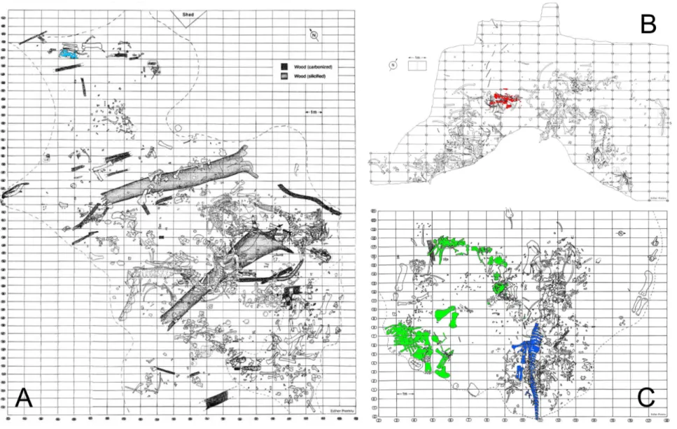
Figure 1.3: Quarry maps of the Howe-Stephens Quarry (a), Howe Quarry (b), and the Howe-Scott Quarry (c), highlighting the specimens included in the phylogenetic analysis (A, light blue: SMA 0009; B, red: SMA 0004; C, green: SMA 0011; C, dark blue: SMA 0087). Quarry maps drawn by Esther Premru, copyright by
Sauriermuseum Aathal.
Figure 2.1: Posterior view of CV 12 of Kaatedocus siberi SMA 0004, showing brittle (arrow) and plastic deformation (lines; indicate the originally horizontal plane of postzygapophyses (above) and transverse processes (below)). Scale bar equals 5 cm.
Figure 2.2: Landmarks used for the retrodeformation methods, shown in CV 10 of Kaatedocus siberi SMA 0004 in posterior, right lateral, and anterior view (from left to right). Only landmarks on right side are shown. The landmarks on the centrum are: 1) anteromedial corners of the parapophyses; 2) posterior ends of the
parapophyses; 3) dorsolateral corner of the border of the cotyle, where the centropostzygapophyseal laminae converge with the centrum; 4) ventrolateral corner of the cotyle, where the posterolateral flanges of the ventral surface of the centrum merge with the border of the cotyle. The landmarks on the neural arch are: 5) anterior ends of prezygodiapophyseal laminae; 6) anterior-most points of prezygapophyses; 7) medial-most point of prezygapophyses; 8) medial sides of insertion of centroprezygapophyseal laminae into prezygapophyses; 9) posterolateral-most points of transverse processes; 10) anterior-most points of the neural spine summit; 11) small protrusions at the center of the neural spine summit; 12) posterior-most point of the neural spine summit; 13) posteromedial corners of postzygapophyses; 14) anterolateral corners of postzygapophyses; 15) posterior ends of spinopostzygapophyseal laminae. The landmark on the cervical rib is its anterior-most tip (16).
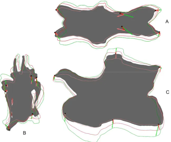
Figure 2.3: Shape changes after two retrodeformation steps in CV 12 of Kaatedocus siberi SMA 0004 in dorsal (A), anterior (B), and left lateral (C) view. The full shape marks the original deformed model, the outlines show the shape of the retrodeformed models (green: SAM, dark and light red: MM, two steps).
Figure 2.4: Outlines of different retrodeformed models of CV 12 of Kaatedocus siberi SMA 0004 obtained by using 4 (green), 9 (blue), or 16 (red) landmarks to define the midsagittal plane. A: results of the MM, B: results of the SAM.
Figure 2.5: Original and retrodeformed models of CV 10 of Kaatedocus siberi SMA 0004 in dorsal (top left), anterior (bottom left), and lateral view (right). Note the elongation of the prezygapophysis in the retrodeformed models (arrow) and the slenderness of the model produced by the MM. Vertebrae not to scale.
Figure 2.6: Original and retrodeformed models of CV 11 of Kaatedocus siberi SMA 0004 in dorsal (top left), anterior (bottom left), and lateral view (right). Note the leveling of the transverse processes in the retrodeformed models (arrows). Vertebrae not to scale.
Figure 2.7: Original and retrodeformed models of CV 12 of Kaatedocus siberi SMA 0004 in dorsal (top left), anterior (bottom left), and lateral view (right). Note the more rounded condyles (arrows) and the pronounced robustness of the model produced by the SAM. Vertebrae not to scale.
Figure 2.8: Original and retrodeformed models of CV 13 of Kaatedocus siberi SMA 0004 in dorsal (top left), anterior (bottom left), and lateral view (right). Note the more pronounced posteroventral corner in the SAM (arrow). Vertebrae not to scale.
Figure 2.9: Original and retrodeformed models of CV 14 of Kaatedocus siberi SMA 0004 in dorsal (top left), anterior (bottom left), and lateral view (right). Note the retraction of the prezygapophyses in the retrodeformed models (arrows) and the robustness of the model produced by the SAM. Vertebrae not to scale.
XI
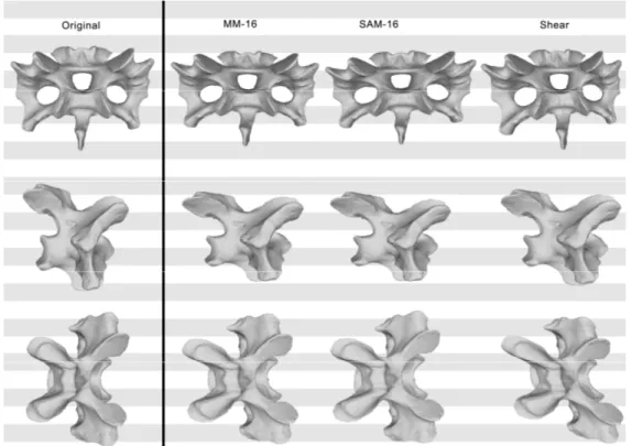
Figure 2.11: Original, deformed (using shear), and retrodeformed models of a cervical vertebra of Raphus cucullatus (DNSM Ornithology 2366) in anterior (top), right lateral (center), and dorsal (bottom) view. Note the dorsoventrally more compressed retrodeformed models compared to the deformed model.
Figure 2.12: Original, deformed (compression and shear combined), and retrodeformed models of a cervical vertebra of Raphus cucullatus (DNSM Ornithology 2366) in anterior (top), right lateral (center), and dorsal (bottom) view. Note the dorsoventrally higher, and anteroposteriorly shorter retrodeformed models compared to the deformed model.
Figure 2.13: Phylogenetic trees (based on Harris, 2006c) recovered with (left) and without (right) the questionable characters (H112 and H114). Bootstrap values indicated if > 50. Note the better resolved tree without the questionable characters. Bootstrap values in the right tree are higher for high-level, but lower for low-level taxa.
Figure 2.14: Phylogenetic trees (based on Whitlock, 2011a) recovered with (left) and without (right) the questionable character (W90). Bootstrap values indicated if > 50. Note the differences in diplodocine intrarelationships. Bootstrap values in the right tree are higher for high-level, but lower for low-level taxa.
Figure 2.15: Calculated midsagittal plane on original model of CV 13 of Kaatedocus siberi SMA 0004 in oblique anterodorsal view. The used symmetrical pairs of landmarks are indicated in yellow and blue, the midsagittal plane in green. Note the medial tuberosity (arrow in close-up), which is supposed to lie on the midsagittal plane, but the methods used herein do not allow to include single points.
Figure 3.1: Quarry map of the holotype of Kaatedocus siberi, SMA 0004. Gray elements represent cervical vertebrae and disarticulated skull elements. Two of the latter were found 15 and 75 cm to the right of this grid (see arrows on the lower right side). SMA 0004 was associated with dorsal ribs, an interclavicle, sternal ribs and chevrons of maybe another individual. Drawing by Esther Premru. Scale bar = 50 cm.
Figure 3.2: Geographical and geological setting of the Howe Quarry within the Upper Jurassic Morrison Formation. The Howe Quarry is located in North Central Wyoming, and stratigraphically well below the clay change. Modified from Schwarz et al. (2007c).
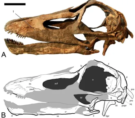
Figure 3.3: A, Photograph and B, drawing of the reconstructed skull of the holotype of Kaatedocus siberi (SMA 0004) in right lateral view. Light gray areas in B are reconstructed parts. The right surangular is mistakenly mounted as left angular. Notes corresponding to diagnostic features: (1) anteriorly restricted squamosal; (2) high tooth count, teeth not restricted to anterior-most jaw. Scale bar = 5 cm.
Figure 3.4: A, Photograph and B, drawing of the reconstructed skull of the holotype of Kaatedocus siberi (SMA 0004) in left lateral view. Light gray areas in B are reconstructed parts. The right surangular is mistakenly mounted as left angular. Note corresponding to diagnostic features: (1) closed or reduced preantorbital foramen. Scale bar = 5 cm.
Figure 3.5: A, Photograph and B, drawing of the reconstructed skull of the holotype of Kaatedocus siberi (SMA 0004) in dorsal view. Light gray areas in B are reconstructed parts. Notes corresponding to diagnostic features: (1) U-shaped frontal notch; (2) rounded snout; (3) narrow, distinct sagittal nuchal crest. Scale bar = 5 cm.
Figure 3.6: A, B, Photographs and C, D, drawings of the reconstructed skull of the holotype of Kaatedocus siberi
(SMA 0004) in anteroventral (A, C), and posterodorsal (B, D) views. Light gray areas in C and D are reconstructed parts. Notes corresponding to diagnostic features: (1) lateral lacrimal spur; (2) postparietal foramen; (3) narrow, distinct sagittal nuchal crest. Scale bar = 5 cm.
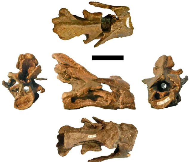
Figure 3.7: Drawings of the atlas–axis complex of the holotype of Kaatedocus siberi (SMA 0004; assignment of axis uncertain, see text) in A, dorsal, B, right lateral, C, ventral, D, posterior, and E, anterior views. Scale bar = 4 cm.
Figure 3.8: Photographs of the atlas-axis complex of the holotype of Kaatedocus siberi (SMA 0004; assignment of axis uncertain, see text) in posterior (left), dorsal (top), right lateral (center), ventral (bottom), and anterior (right) views. Scale bar = 4 cm.
Figure 3.9: A, Photograph and B, C, drawings of the anterior cervical vertebrae of the holotype of Kaatedocus siberi (SMA 0004). Photographs in lateral view and to scale, elements shown in the drawings are indicated by an asterisk. Drawings of CV 5 (B), and CV 3 (C) in dorsal (1), lateral (2), ventral (3), posterior (4) and anterior (5) views; scaled to the same centrum length, in order to highlight changes of proportions. Scale bars = 4 cm.
XII
(top), right lateral (center), ventral (bottom), and anterior (right) views. Scale bar = 4 cm.
Figure 3.11: Photographs of CV 4 of the holotype of Kaatedocus siberi (SMA 0004) in posterior (left), dorsal (top), right lateral (center), ventral (bottom), and anterior (right) views. Scale bar = 4 cm.
Figure 3.12: Photographs of CV 5 of the holotype of Kaatedocus siberi (SMA 0004) in posterior (left), dorsal (top), right lateral (center), ventral (bottom), and anterior (right) views. Scale bar = 4 cm.
Figure 3.13: A, Photograph and B, drawings of the mid-cervical vertebrae of the holotype of Kaatedocus siberi
(SMA 0004). Photograph in lateral view and to scale, CV 8 shown in the drawings is indicated by an asterisk. Drawings of CV 8 (B) in dorsal (1), lateral (2), ventral (3), posterior (4) and anterior (5) views. Scale bars = 4 cm.
Figure 3.14: Photographs of CV 6 of the holotype of Kaatedocus siberi (SMA 0004) in posterior (left), dorsal (top), right lateral (center), ventral (bottom), and anterior (right) views. Scale bar = 4 cm.
Figure 3.15: Photographs of CV 7 of the holotype of Kaatedocus siberi (SMA 0004) in posterior (left), dorsal (top), right lateral (center), ventral (bottom), and anterior (right) views. Scale bar = 4 cm.
Figure 3.16: Photographs of CV 8 of the holotype of Kaatedocus siberi (SMA 0004) in posterior (left), dorsal (top), right lateral (center), ventral (bottom), and anterior (right) views. Scale bar = 4 cm.
Figure 3.17: Photographs of CV 9 of the holotype of Kaatedocus siberi (SMA 0004) in posterior (left), dorsal (top), right lateral (center), ventral (bottom), and anterior (right) views. Scale bar = 4 cm.
Figure 3.18: Photographs of CV 10 of the holotype of Kaatedocus siberi (SMA 0004) in posterior (left), dorsal (top), right lateral (center), ventral (bottom), and anterior (right) views. Scale bar = 4 cm.
Figure 3.19: A, Photographs and B, C, drawings of the posterior CV of the holotype of Kaatedocus siberi (SMA 0004). Photographs in lateral view and to scale, elements shown in the drawings indicated by an asterisk. Drawings of CV 14 (B), and CV 11 (C) in dorsal (1), lateral (2), ventral (3), posterior (4) and anterior (5) views; scaled to the same centrum length, in order to highlight changes of proportions. Arrows in C2 mark possible bite marks. Scale bars = 4 cm.
Figure 3.20: Photographs of CV 11 of the holotype of Kaatedocus siberi (SMA 0004) in posterior (left), dorsal (top), right lateral (center), ventral (bottom), and anterior (right) views. Scale bar = 4 cm.
Figure 3.21: Photographs of CV 12 of the holotype of Kaatedocus siberi (SMA 0004) in posterior (left), dorsal (top), right lateral (center), ventral (bottom), and anterior (right) views. Scale bar = 4 cm.
Figure 3.22: Photographs of CV 13 of the holotype of Kaatedocus siberi (SMA 0004) in posterior (left), dorsal (top), right lateral (center), ventral (bottom), and anterior (right) views. Scale bar = 4 cm.
Figure 3.23: Photographs of CV 14 of the holotype of Kaatedocus siberi (SMA 0004) in posterior (left), dorsal (top), right lateral (center), ventral (bottom), and anterior (right) views. Scale bar = 4 cm.
Figure 3.24: Nelsen Consensus tree obtained from a heuristic search in WinClada (six most parsimonious trees; tree length = 388; CI = 64%; RI = 57%). Dots indicate ambiguous (white) and unambiguous (black)
synapomorphies, and autapomorphies of the respective clade. The corresponding character number and scoring is indicated above and below the dots, respectively. Main clades are indicated by their name, and bootstrap as well as Bremer Support values are given for each node (Bremer Support in square brackets). Kaatedocus siberi
is resolved as Diplodocinae more basal than Tornieria africana, Barosaurus lentus and Diplodocus.
Figure 3.25: Life reconstruction of the skull of Kaatedocus siberi. Note the lateral spur on the lacrimal and the palpebral element covering the orbit. Illustration by Davide Bonadonna (Milan).
Figure 4.1: Compiled quarry map of the two excavation periods at the Howe Quarry (AMNH map below; SMA map above). Arrows indicate supposed clavicles at SMA, arrowheads possible locations of the supposed clavicle at AMNH. Circles indicate gastral or sternal baskets (full circles: SMA; dashed circles: AMNH), rectangle marks the SMA pair of symmetrical bones. AMNH map modified from Bird (1985); SMA map drawn by Esther Premru.
Figure 4.2: Detail of the 1991 quarry map, with sections producing associated morphotype C–E elements enlarged (from left to right: clusters M 21, F 27 and D 28). The morphotype C–E elements are highlighted in gray in the enlarged sections.
XIII
(d) SMA L 22-3; (e) SMA L 27-7. Scale bar = 10 cm. Gray areas in (a) indicate broken surfaces. Note the bifurcate end on top and the spatulate end at the bottom.
Figure 4.4: Photographs of morphotype A element AMNH 30900. Scale bar = 10 cm.
Figure 4.5: Photographs of morphotype A element SMA I 24-4. Scale bar = 10 cm.
Figure 4.6: Photographs of morphotype A element SMA M 25-3. Scale bar = 10 cm.
Figure 4.7: Photographs of morphotype A element SMA L 22-3. Scale bar = 10 cm.
Figure 4.8: Photographs of morphotype A element SMA L 27-7. Scale bar = 10 cm.
Figure 4.9: Drawings of the pair of morphotype B elements SMA K 24-3 (outer bone) and SMA K 24-6 (inner bone) in internal (a) and external (b) view. Short leg of L-shaped bones shown in perpendicular view below. Note the considerable bend of this portion in respect to the main axis of the bone. Scale bar = 10 cm.
Figure 4.10: Photographs of the morphotype B element SMA K 24-6. Scale bar = 5 cm.
Figure 4.11: Photographs of the morphotype B element SMA K 24-3. Scale bar = 10 cm.
Figure 4.12: Drawings of the pair of morphotype B elements AMNH 30789 in internal (a) and external (b) view. Scale bar = 10 cm.
Figure 4.13: Photographs of the left morphotype B element AMNH 30789. Scale bar = 10 cm.
Figure 4.14: Photographs of the right morphotype B element AMNH 30789. Scale bar = 10 cm.
Figure 4.15: Morphotype B elements of the diplodocid DQ-SB, articulated with the acromia (arrowheads) of the scapulae, as they were found. Co, coracoid; MB, morphotype B element; Sc, scapula. Picture courtesy of H. Galiano.
Figure 4.16: Coracoid with taphonomically attached morphotype B element (MB) of the non-somphospondylian macronarian SMA 0009 in posteroventral (a) and lateral (b) view. Coracoid made semitransparent in order to visualize better the morphotype B element. Arrows indicate brightly colored matrix present between the MB and the coracoid. CF, coracoid foramen; GL, glenoid surface. Scale bar = 2 cm.
Figure 4.17: Drawings of morphotype C elements SMA H 20-7 (a) and L 21-5 (b). Both elements are incomplete, fracture surface at the top is indicated by the gray area. Scale bar = 10 cm.
Figure 4.18: Photographs of the morphotype C element SMA H 20-7. Scale bar = 10 cm.
Figure 4.19: Photographs of the morphotype C element SMA L 21-5. Scale bar = 10 cm.
Figure 4.20: Drawings of morphotype D elements SMA D 28-5 (a), M 21-2 (b) and M 21-8 (c). The bottom end of M 21-8 is broken. Scale bar = 10 cm.
Figure 4.21: Photographs of the morphotype D element SMA D 28-5. Scale bar = 10 cm.
Figure 4.22: Photographs of the morphotype D element SMA M 21-2. Scale bar = 10 cm.
Figure 4.23: Photographs of the morphotype D element SMA M 21-8. Scale bar = 10 cm.
Figure 4.24: Proposed articulation between two morphotype D elements (left, SMA D 5; right, SMA D 28-14) in three views (internal/dorsal view in the center, gray lines indicate the same morphological landmarks on the respective elements). Note the similarity to the central portion of the fused morphotype D element (Fig. 4.23). Scale bar = 5 cm.
Figure 4.25: Drawings of morphotype E elements SMA H 21-3 (a), N 22-12 (b) and M 21-15 (c). Note the irregular shapes that do not allow an assignation to any other morphotype. Dotted lines in (a) indicate direction of the broken hook-like projection. Scale bar = 10 cm.
Figure 4.26: Photographs of morphotype E element SMA M 21-15. Scale bar = 10 cm.
Figure 4.27: Photographs of morphotype E element SMA N 22-12. Scale bar = 10 cm.
XIV
sternal plates; SR, sternal ribs (morphotypes C and E); VC, vertebral column. Modified from Schwarz et al. (2007a; a) and Filla and Redman (1994; b).
Figure 4.29: Evolution of the furcula, comparison between the two hypotheses. Note the gap within
Dinosauriformes in the furcula-interclavicle hypothesis. Line drawings scaled to same size. Eaton and Stewart (1960: Hesperoherpeton); Chatterjee (1978: Parasuchus); Klima (1987: Ornithorhynchus); Rieppel (1992:
Lacerta); Steyer et al. (2000: Aphanerama); Benton and Walker (2002: Erpetosuchus); Martz (2002:
Typothorax); Vickaryous and Hall (2006: Dimetrodon; 2010: Alligator, Basilicus, Gallus, Leptoceratops); Remes (2008: Euparkeria); Dilkes and Sues (2009: Doswellia).
Figure 5.1: Quarry map of SMA 0011, indicating the single bones found. Note the separation of the cervical series and the skull from the dorsal column and the appendicular skeleton. Color code: skull (orange), CV (red), DV (violet), DR and SR (yellow), PcG (light green), PvG (dark green), Fl (light blue), Hl (dark blue). Abb.: Bc, braincase; co, coracoid; CR, cervical rib; CV, cervical vertebra; DR, dorsal ribs; DV, dorsal vertebra; fe, femur; fi, fibula; Fl, forelimb; h, humerus; Hl, hindlimb; il, ilium; is, ischium; Ma, manus; PcG, pectoral girdle; Pe, pes; pu, pubis; PvG, pelvic girdle; r, radius; sc, scapula; SR, sternal ribs; SV, sacral vertebrae; tb, tibia; u, ulna. Map drawn by Esther Premru.
Figure 5.2: Quarry map of SMA 0087, without bones of other specimens found close-by. Abb.: DR, dorsal ribs; DV, dorsal vertebra; fe, femur; fi, fibula; il, ilium; is, ischium; Pe, pes; pu, pubis; SR, sternal ribs; SV, sacral vertebrae; tb, tibia. Map drawn by Esther Premru.
Figure 5.3: Skull bones of SMA 0011 before mounting. Black elements were lacking and reconstructed for the mounted skull. Abb.: an, angular; aof, antorbital fenestra; at, atlas; Bc, braincase; d, dentary; f, frontal; j, jugal; la, lacrimal; m, maxilla; na, nasal; pf, prefrontal; pm, premaxilla; pra, proatlas; q, quadrate; qj, quadratojugal; sa, surangular; T, teeth. Scale bar = 10 cm. Photo by Urs Möckli.
Figure 5.4: Skull of SMA 0011 as usually figured in anterodorsal (top), posterodorsal (left), right lateral (bottom center), and rostral views (right). Dark elements were lacking and reconstructed for the mounted skull. Abb.: an, angular; aof, antorbital fenestra; bo, basioccipital; bpr, basipterygoid process; d, dentary; ex, exoccipital; f, frontal; j, jugal; ltf, laterotemporal fenestra; m, maxilla; n, external nares; na, nasal; o, orbit; os, orbitosphenoid; p, parietal; paof, preantorbital fossa; pf, prefrontal; pm, premaxilla; po, postorbital; popr, paroccipital process; pro, prootic; q, quadrate; qj, quadratojugal; sa, surangular; so, supraoccipital; sq, squamosal; stf, supratemporal fenestra. Scale bar = 10 cm.
Figure 5.5: Skull of SMA 0011 in supposed habitual pose in dorsal (top), anterior (left), left lateral (bottom center), and posterior views (right). Dark elements were lacking and reconstructed for the mounted skull. Abb.: an, angular; aof, antorbital fenestra; bo, basioccipital; bpr, basipterygoid process; bt, basal tubera; cpr, crista prootica; d, dentary; ex, exoccipital; f, frontal; fm, foramen magnum; j, jugal; ltf, laterotemporal fenestra; m, maxilla; n, external nares; na, nasal; o, orbit; os, orbitosphenoid; p, parietal; pf, prefrontal; pm, premaxilla; po, postorbital; popr, paroccipital process; pro, prootic; ptf, posttemporal fenestra; q, quadrate; qj, quadratojugal; sa, surangular; so, supraoccipital; sq, squamosal; stf, supratemporal fenestra. Scale bar = 10 cm.
Figure 5.6: Skull reconstruction of Galeamopus shellensis in dorsal and lateral view, created by Simao Mateus (ML), and based on SMA 0011. Lacking bones were reconstructed after Diplodocus (Whitlock, 2011b).
Figure 5.7: Maxillary canal in the skull of SMA 0011 (arrow in the inlet) in right lateral view. The canal is herein interpreted as an autapomorphy of Galeamopus shellensis. Abb.: aof, antorbital fenestra; j, jugal; m, maxilla; paof, preantorbital fossa. Scale bar in skull overview = 10 cm.
Figure 5.8: Unusual development of sagittal nuchal crest in the skull of SMA 0011 (arrow in the inlet) in posterodorsal view. The complex structure indicates that there might have been an additional element lacking, but no such bone has yet been described in any sauropod skull. Abb.: f, frontal; p, parietal; so, supraoccipital. Scale bar in skull overview = 10 cm.
Figure 5.9: Right pterygoid of SMA 0011 in lateral (A) and medial (B) views. The element is only partly prepared, the lighter color is matrix adhered to the darker bone. Abb.: ar, anterior ramus; er, ectopterygoid ramus; qr, quadrate ramus. Scale bar = 5 cm.
Figure 5.10: Right hyoid of SMA 0011 in medial (A) and lateral (B) views. Abb.: ar, anterior ramus; sqr, squamosal ramus. Scale bar = 10 cm.
XV
Figure 5.12: Teeth of SMA 0011. They were found disarticulated from the skull. Abb.: tc, tooth crown; tr, tooth root. Scale bar = 2 cm.
Figure 5.13: Right proatlas of SMA 0011 in lateral (A) and medial (B) views. Note the elongate and narrow distal tip. Scale bar = 2 cm.
Figure 5.14: Atlas and axis of SMA 0011. A shows the two elements in an articulated state, B show the neurapophyses in lateral (B1) and medial (B2) views. Abb.: acdl, anterior centrodiapophyseal lamina; at, atlas; avl, anteroventral lip; ax, axis; axr, axial rib; cpol, centropostzygapophyseal lamina; di, diapophysis; dip, distal process; epi, epipophyses; lsp, lateral spur; mp, medial process; ncs, neurocentral synostosis; pl, pleurocoel; podl, postzygodiapophyseal lamina; poz, postzygapophysis; prdl, prezygodiapophyseal lamina; prsl, prespinal lamina; spol, spinopostzygapophyseal lamina; vk, ventral keel. Scale bars = 10 cm.
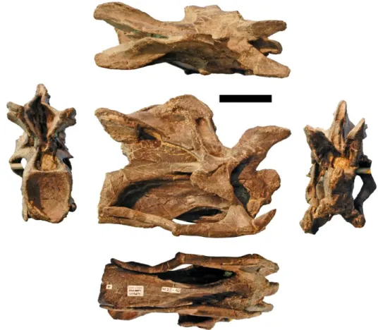
Figure 5.15: Cervical vertebrae 3 to 6 of SMA 0011 in right lateral view. Abb.: acdl, anterior centrodiapophyseal lamina; apf, anterior pneumatic fossa; cpol, centropostzygapophyseal lamina; cprl, centroprezygapophyseal lamina; di, diapophysis; dsf, dorsal spinal fossa; epi, epipophysis; naf, neural arch foramen; ncs, neurocentral synostosis; pap, parapophysis; pcdl, posterior centrodiapophyseal lamina; pl, pleurocoel; podl,
postzygodiapophyseal lamina; poz, postzygapophysis; ppf, posterior pneumatic fossa; prdl, prezygodiapophyseal lamina; pre, pre-epipophysis; prsl, prespinal lamina; prz, prezygapophysis; pvf, posteroventral flange; pvfo, posteroventral fossa; spol, spinopostzygapophyseal lamina; sprl, spinoprezygapophyseal lamina; vk, ventral keel; vsf, ventral spinal fossa. Scale bar = 10 cm.
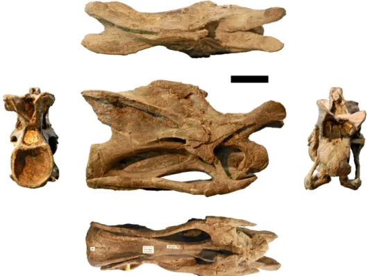
Figure 5.16: Cervical vertebrae 8 and 9 of SMA 0011 in right lateral view. Note the open neurocentral synchondrosis. Abb.: acdl, anterior centrodiapophyseal lamina; al, accessory lamina; apf, anterior pneumatic fossa; asl, accessory spinal lamina; bns, bifid neural spine; cpol, centropostzygapophyseal lamina; cprl, centroprezygapophyseal lamina; di, diapophysis; epi, epipophysis; naf, neural arch foramen; ncs, neurocentral synchondrosis; pap, parapophysis; pcdl, posterior centrodiapophyseal lamina; podl, postzygodiapophyseal lamina; poz, postzygapophysis; ppf, posterior pneumatic fossa; prdl, prezygodiapophyseal lamina; pre, pre-epipophysis; prz, prezygapophysis; pvf, posteroventral flange; pvfo, posteroventral fossa; spol,
spinopostzygapophyseal lamina; sprl, spinoprezygapophyseal lamina; vsf, ventral spinal fossa. Scale bar = 10 cm.
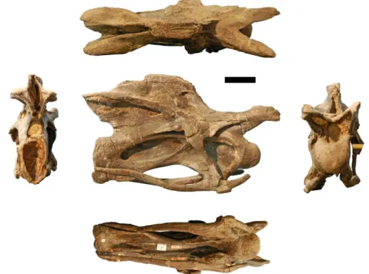
Figure 5.17: Cervical vertebrae 11 and 12 of SMA 0011 in right lateral view. Abb.: al, accessory lamina; apf, anterior pneumatic fossa; asl, accessory spinal lamina; bns, bifid neural spine; cpol, centropostzygapophyseal lamina; cprl, centroprezygapophyseal lamina; di, diapophysis; mt, median tubercle; naf, neural arch foramen; pap, parapophysis; pcdl, posterior centrodiapophyseal lamina; podl, postzygodiapophyseal lamina; poz, postzygapophysis; ppf, posterior pneumatic fossa; prdl, prezygodiapophyseal lamina; pre, pre-epipophysis; prz, prezygapophysis; pvf, posteroventral flange; pvfo, posteroventral fossa; spol, spinopostzygapophyseal lamina; sprl, spinoprezygapophyseal lamina. Scale bar = 10 cm.
Figure 5.18: Cervical vertebra 15 of SMA 0011 in right lateral view. Articulated DV 1 shaded. Abb.: acdl, anterior centrodiapophyseal lamina; al, accessory lamina; cpol, centropostzygapophyseal lamina; cprl,
centroprezygapophyseal lamina; di, diapophysis; ncs, neurocentral synostosis; pap, parapophysis; pcdl, posterior centrodiapophyseal lamina; pl, pleurocoel; podl, postzygodiapophyseal lamina; poz, postzygapophysis; prdl, prezygodiapophyseal lamina; prz, prezygapophysis; pvf, posteroventral flange; spol, spinopostzygapophyseal lamina; sprl, spinoprezygapophyseal lamina. Scale bar = 10 cm.
Figure 5.19: Neurocentral synostosis in CV 5 of SMA 0011. Detail of the vertebra in right lateral view. Note the higher degree of fusion in the posterior portion compared to the anterior part (arrows). Abb.: apf, anterior pneumatic fossa; cpol, centropostzygapophyseal lamina; di, diapophysis; pcdl, posterior centrodiapophyseal lamina; podl, postzygodiapophyseal lamina; poz, postzygapophysis; ppf, posterior pneumatic fossa; pvfo, posteroventral fossa.
Figure 5.20: Neural arch foramina in CV 9 of SMA 0011, in posterodorsal view. The foramina are highlighted with the semi-transparent overlay. Abb.: bns, bifid neural spine; epi, epipophysis; mt, median tubercle; naf, neural arch foramen; pap, parapophysis; poz, postzygapophysis; ppf, posterior pneumatic fossa; prdl,
prezygodiapophyseal lamina; prz, prezygapophysis; pvfo, posteroventral fossa; spol, spinopostzygapophyseal lamina; sprl, spinoprezygapophyseal lamina. Scale bar = 10 cm.
XVI
prezygapophysis; pvf, posteroventral flange; spol, spinopostzygapophyseal lamina; sprl, spinoprezygapophyseal lamina. Scale bar = 10 cm.
Figure 5.22: Dorsal vertebra 2 of SMA 0011 in right lateral view. Articulated DV 1 and DV 3 shaded. The right metapophysis is lacking, only the medial face of the left one is visible. Note the broken diapophysis that reveals the inner structure. Abb.: cpol, centropostzygapophyseal lamina; cprl, centroprezygapophyseal lamina; di, diapophysis; pap, parapophysis; pl, pleurocoel; poz, postzygapophysis; prdl, prezygodiapophyseal lamina; prz, prezygapophysis; spol, spinopostzygapophyseal lamina; sprl, spinoprezygapophyseal lamina. Scale bar = 10 cm.
Figure 5.23: Dorsal vertebra 3 of SMA 0011 in right lateral view. Articulated DV 2 and partial DV 4 shaded. The right metapophysis is lacking, only the medial face of the left one is visible. The broken right
prezygapophysis is present on top of the broken diapophysis. Abb.: DV, dorsal vertebra; ncs, neurocentral suture; pap, parapophysis; pl, pleurocoel; prz, prezygapophysis; spol, spinopostzygapophyseal lamina; sprl, spinoprezygapophyseal lamina; vk, ventral keel. Scale bar = 10 cm.
Figure 5.24: Dorsal vertebral centrum 4 of SMA 0011 in anterior (A), dorsal (B), and left lateral (C) views. The element is still partly preserved within matrix. Abb.: nc, neural canal; ncs, neurocentral synostosis; pl,
pleurocoel. Scale bar = 10 cm.
Figure 5.25: Dorsal vertebra 5 of SMA 0011 in posterolateral (A) and right lateral view (B). The element lacks the right half of the neural spine, and is partly mounted in matrix. Grey lines indicate the probable extensions of the right half. Note that the tip of the left diapophysis is reconstructed. Abb.: di, diapophysis; nc, neural canal; pap, parapophysis; pl, pleurocoel; poz, postzygapophysis; prz, prezygapophysis; spdl, spinodiapophyseal lamina; spol, spinopostzygapophyseal lamina; sprl, spinoprezygapophyseal lamina. Scale bar = 10 cm.
Figure 5.26: Dorsal vertebrae 6 to 10 of SMA 0011 in right lateral (A), posterolateral (B), and anterolateral view (C). The elements are partly preserved in matrix. Note the open neurocentral synchondrosis in DV 7 to DV 10. Abb.: cpol, centropostzygapophyseal lamina; DV, dorsal vertebra; lspol, lateral spinopostzygapophyseal lamina; pap, parapophysis; pcdl, posterior centrodiapophyseal lamina; pcpl, posterior centroparapophyseal lamina; pl, pleurocoel; podl, postzygodiapophyseal lamina; posl, postspinal lamina; poz, postzygapophysis; prdl, prezygodiapophyseal lamina; prpl, prezygoparapophyseal lamina; prsl, prespinal lamina; spdl,
spinodiapophyseal lamina; sprl, spinoprezygapophyseal lamina. Scale bar in A = 10 cm, DV 6 in A and C, and DV 10 in A and B are scaled to the same vertebral height.
Figure 5.27: Scapula and coracoid of SMA 0011 in right lateral view. Lacking parts indicated with dashed lines. Abb.: acr, acromion ridge; CF, coracoid foramen; co, coracoid; GL, glenoid; sc, scapula. Scale bar = 20 cm.
Figure 5.28: Forelimb of SMA 0011 in anterior view: A) humerus, B) antebrachium and manus (as mounted within matrix). Note that the carpal was probably mounted upside down. Abb.: c, carpal; dpc, deltopectoral crest; hh, humeral head; lr, lateral ridge; mc, metacarpal; mr, medial ridge; phm, manual phalanx; r, radius; rt, tubercle for articulation with radius; u, ulna; ut, tubercle for articulation with ulna. Scale bar (valid for both A and B) = 20 cm.
Figure 5.29: Left manual phalanx I-1 of SMA 0011 in posterior view. Note the distinct posteroventral lip and posterolateral crest. Abb.: lco, lateral condyle; mco, medial condyle; plc, posterolateral crest; pvl, posteroventral lip. Scale bar = 2 cm.
Figure 5.30: Possible preservation of keratinous sheet on left manual ungual I-2 of SMA 0011 (medial view). Note the different surface texture at the tip (arrow), compared to more posterior portions. Abb.: dg, distal groove; pas, proximal articular surface. Scale bar = 5 cm.
Figure 5.31: Right pubis (A) and left ischium (B) of SMA 0011 in medial view. The distal end of the ischium is reconstructed. Abb.: ac, acetabular surface; amb, ambiens process; ip, iliac peduncle; isa, ischial articular surface; of, obturator foramen; pua, pubic articulation. Scale bar = 20 cm.
Figure 5.32: Left hindlimb of SMA 0011: A) femur in posterior view; B) tibia and fibula in anterior view, as mounted. The lacking greater trochanter of the femur is indicated by the dashed line. Abb.: cc, cnemial crest; ec, epicondyle; fh, femoral head; fi, fibula; fic, fibular condyle; icg, intercondylar groove; tb, tibia; tic, tibial condyle. Scale bar = 20 cm.
Figure 5.33: Left astragalus of SMA 0011 in anterior (A) and lateral (B) view. Due to the mounted state, a portion of the tibia, obscuring a posterodorsal part of the astragalus is masked as semitransparent. Abb.: asp, ascending process; dro, distal roller; fif, fibular facet; tb, tibia; tif, tibial facet. Scale bar = 5 cm.
XVII
V. Elements partially overlapping the other bones are marked by a black line. Abb.: dlr, dorsolateral ridge; icg, intercondylar groove; mts, metatarsal; nf, nutrient foramen; plp, posterolateral process. Scale bar = 10 cm.
Figure 5.35: Left pedal phalanges of SMA 0011 in dorsal view, as mounted. Php IV-1 could actually also be php III-2 or php V-1 (see text). Abb.: php, pedal phalanx; ung, ungual. Scale bar = 10 cm.
Figure 5.36: Dorsal centrum 6 of SMA 0087 in left, posterior, right, anterior (top left to right), and ventral view (bottom). Abb.: cpol, centropostzygapophyseal lamina; cprl, centroprezygapophzseal lamina; nc, neural canal; pl, pleurocoel. Scale bar = 10 cm.
Figure 5.37: Dorsal neural spine 6 of SMA 0087 in left, right, and ventral (bottom) view. Note the anterior and dorsal spurs on the diapophysis. Abb.: cpol, centropostzygapophyseal lamina; das, diapophysis anterior spur; dds, diapophysis dorsal spur; di, diapophysis; hya, hypantrum; hys, hyposphene; lspol, lateral spol; mspol, medial spol; pap, parapophysis; pcdl, posterior centrodiapophyseal lamina; pcpl, posterior centroparapophyseal lamina; podl, postzygodiapophyseal lamina; posl, postspinal lamina; poz, postzygapophysis; prdl,
prezygodiapophyseal lamina; prpl, prezygoparapophyseal lamina; prsl, prespinal lamina; prz, prezygapophysis; spdl, spinodiapophyseal lamina; spol, spinopostzygapophyseal lamina; sprl, spinoprezygapophyseal lamina. Scale bar = 10 cm.
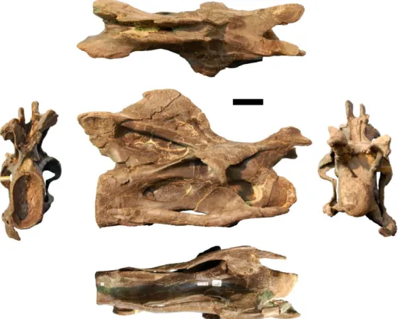
Figure 5.38: Caudal vertebra 5 of SMA 0087 in anterior, left lateral, and posterior view (from left to right). Note the foramen that pierces the ventral surface, and the dorsally expanded transverse processes. Abb.: chf, chevron facet; nf, nutrient foramen; posl, postspinal lamina; poz, postzygapophysis; prsl, prespinal lamina; prz,
prezygapophysis; spol, spinopostzygapophyseal lamina; sprl, spinoprezygapophyseal lamina; tp, transverse process. Scale bar = 10 cm.
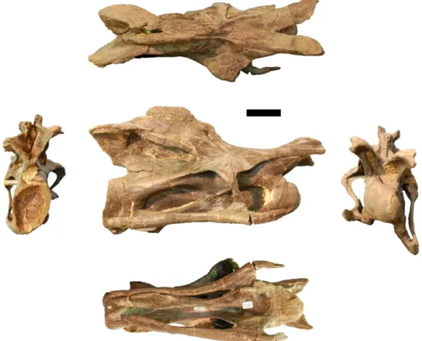
Figure 5.39: Caudal vertebra 7 of SMA 0087 in posterior, right lateral, and anterior view (left to right). Abb.: cpol, centropostzygapophyseal lamina; cprl, centroprezygapophyseal lamina; posl, postspinal lamina; poz, postzygapophysis; prsl, prespinal lamina; prz, prezygapophysis; spol, spinopostzygapophyseal lamina; sprl, spinoprezygapophyseal lamina; tp, transverse process. Scale bar = 10 cm.
Figure 5.40: Caudal vertebra 16 of SMA 0087 in dorsal (top), posterior (left) and right lateral view (bottom right). Note the presence of two weak longitudinal ridges on the centrum. Abb.: chf, chevron facets; lr, lateral ridge; prsl, prespinal lamina; prz, prezygapophysis; poz, postzygapophysis; sprl, spinoprezygapophyseal lamina; vlr, ventrolateral ridge. Scale bar = 10 cm.
Figure 5.41: Anterior chevron of SMA 0087 in anterior, right lateral, and posterior view (left to right). This chevron was found between Cd 2 and 3. Note the bridged over haemal canal. Abb.: hc, haemal canal. Scale bar = 10 cm.
Figure 5.42: Mid-chevron of SMA 0087 in anterior, left lateral, posterior, right lateral (top, left to right), and ventral view (bottom). This chevron was recovered associated with Cd 16 to 18. Note the ventral slit visible in ventral view. Abb.: ap, anterior process; hc, haemal canal; pp, posterior process. Scale bar = 10 cm.
Figure 5.43: Sternal rib of SMA 0087. Corresponds to Morphotype C of Tschopp and Mateus (2013). Scale bar = 10 cm.
Figure 5.44: Sternal or gastral rib of SMA 0087. Corresponds to morphotype C of Tschopp and Mateus (2013). Note the longitudinal sulcus (arrow), which might indicate a gastral instead of a sternal origin. Scale bar = 10 cm.
Figure 5.45: Right astragalus of SMA 0087 in dorsal (top), posterior (center left), ventral (bottom), and anterior view (center right). Abb.: af, astragalar foramen; asp, ascending process; dro, distal roller; fif, fibular facet; tif, tibial facet. Scale bar = 10 cm.
Figure 5.46: Right metatarsal I of SMA 0087 in proximal (top), dorsal, medial, plantar, lateral (center left to right), and distal view (bottom). Abb.: dlr, dorsolateral ridge; nf, nutrient foramen; plp, posterolateral process. Scale bar = 10 cm.
Figure 5.47: Right metatarsal II of SMA 0087 in proximal (top), dorsal, medial, plantar, lateral (center left to right), and distal view (bottom). Abb.: dlr, dorsolateral ridge; plp, posterolateral process. Scale bar = 10 cm.
Figure 5.48: Right metatarsal V of SMA 0087 in proximal (top), dorsal, medial, plantar, lateral (center left to right), and distal view (bottom). Scale bar = 10 cm.
XVIII
Figure 5.50: Right pedal phalanx II-1 of SMA 0087 in proximal (top), dorsal, medial, plantar, lateral (center left to right), and distal view (bottom). Abb.: nf, nutrient foramen. Scale bar = 5 cm.
Figure 5.51: Right pedal phalanx II-2 of SMA 0087 in proximal (top), dorsal, medial, plantar, lateral (center left to right), and distal view (bottom). Scale bar = 5 cm.
Figure 5.52: Right pedal ungual I-2 of SMA 0087 in dorsal (top), medial, lateral (center left, right), and plantar view (bottom). Abb.: ps, proximal spur; Scale bar = 10 cm.
Figure 5.53: Right pedal ungual II-3 of SMA 0087 in dorsal (top), medial, lateral (center left, right), and plantar view (bottom). Scale bar = 10 cm.
Figure 6.1: Skulls of Mamenchisaurus youngi (A; modified from Ouyang and Ye, 2002), Camarasaurus sp. USNM 13786 (B; photo from O. Mateus), Giraffatitan brancai (C; modified from Janensch, 1935), Diplodocus
sp. CM 11161 (D), and Galeamopus shellensis SMA 0011 (E) in lateral view, illustrating the states of the characters 1, 5, 13, 14, 15, 19, 20, 21, 37, 38, 39, 45, 46, 55, 113. Not to scale.
Figure 6.2: Anterior portions of premaxillae of Camarasaurus (A; modified from Madsen et al., 1995) and
Galeamopus shellensis SMA 0011 (B) in anterodorsal view, illustrating the states of characters 2 and 3. Not to scale.
Figure 6.3: Skulls (A, C-E) or maxilla (B) of Camarasaurus sp. SMA 0002 (A; photo by O. Mateus),
Dicraeosaurus hansemanni MB.R.2336 (B), Kaatedocus siberi SMA 0004 (C), Galeamopus shellensis SMA 0011 (D; photo by O. Mateus), and Diplodocus sp. CM 11161 (E) in anterolateral view, illustrating the states of the characters 6, 9, 10, 11, 12, 16, 17, 48. Not to scale.
Figure 6.4: Premaxillae of Suuwassea emilieae ANS 21122 (A), Dicraeosaurus hansemanni MB.R.2337 (B), and Diplodocus sp. USNM 2673 (C, left element reversed) in lateral view, illustrating the states of character 7. Not to scale.
Figure 6.5: Skulls of Camarasaurus (A; modified from Wilson and Sereno, 1998), Limaysaurus tessonei
MUCPv-205 (B; photo by J. Whitlock), Dicraeosaurus hansemanni MB.R.2379 (C), Kaatedocus siberi SMA
0004 (D) and Diplodocus sp. CM 11161 (E)in dorsal view, illustrating the states of the characters 8, 26, 29, 30, 34, 35, 36, 66. Not to scale.
Figure 6.6: Skull roof of Diplodocus sp. CM 11161 (A; based on Wilson and Sereno, 1998) and Limaysaurus tessonei MUCPv-205 (B; based on Calvo and Salgado, 1995) in dorsal view. Note the anteromedial hook in the prefrontal of CM 11161 (A; C23-1), and the differently shaped frontal-nasal suture (straight to anteriorly bowed in A, C28-0; bowed posteriorly in B, C28-1). Abb.: f, frontal; na, nasal; pf, prefrontal. Scaled to the same skull roof length.
Figure 6.7: Left (F, H-K) and right (A-E, G) diplodocoid frontals in dorsal view, anterior to the front. The upper row shows elements with an anteriorly restricted posterior process of the prefrontal (C23-0), the lower row have elongated posterior processes (C23-1). Additional states are illustrated from the characters 24, 31, 33. Frontals figured in strict perpendicular view, and scaled to the same anteroposterior length.
Figure 6.8: Left jugal of Diplodocus USNM 2672 in lateral view, illustrating the large contribution of the jugal to the antorbital fenestra (C40-1), the narrow and elongate posteroventral process (C42-1), the dorsal process of the jugal (C43-0), and the anterior spur (C44-1). Abb.: aof, antorbital fenestra; j, jugal; la, lacrimal; ltf,
laterotemporal fenestra; m, maxilla; o, orbit; po, postorbital; qj, quadratojugal.
Figure 6.9: Skulls of Shunosaurus lii ZG 65430 (A; modified from Chatterjee and Zheng, 2002) and Diplodocus
sp. CM 11161 (B) in ventral view. Note the anteriorly displaced position of the ectopterygoid ramus of the pterygoid, and the ectopterygoid itself, in Diplodocus (B; C41-1 and C102-1), as well as the vomer that articulates with the premaxilla in Shunosaurus (A; C103-0), but with the maxilla in Diplodocus (B; C103-1). Abb.: aof, antorbital fenestra; bo, basioccipital; bpr, basipterygoid process; bt, basal tuber; ep, ectopterygoid; er, ectopterygoid ramus; j, jugal; m, maxilla; pa, palate; pm, premaxilla; popr, paroccipital process; pt, pterygoid; qj, quadratojugal; v, vomer. Pictures scaled to the same skull length.
Figure 6.10: Quadrate articular surface shapes of Camarasaurus sp. SMA 0002 (left, quadrangular, C49-0),
Suuwassea emilieae ANS 21122 (center, roughly triangular, C49-1), and Nigersaurus taqueti GAD512-7 (right, crescent-shaped, C49-2). Figures of Suuwassea and Nigersaurus traced from Harris (2006a) and Sereno et al. (2007), respectively.
XIX
posterior view, illustrating the transverse ridge (B, inlet; C50-1), and the deep (A; C51-0) versus shallow (B; C51-1) quadrate fossa. Not to scale.
Figure 6.12: Quadrates of Camarasaurus sp. SMA 0002 (A) and Diplodocidae indet. SMA D27-7 (B) in medial view, illustrating the second medial fossa (B; C52-1), the shape of the dorsal margin (C53, concave versus convex), and the stocky versus slender posterior ramus (C54). Scaled to the same height.
Figure 6.13: Squamosal and adjacent bones in Mamenchisaurus youngi (A; traced from Ouyang and Ye, 2002),
Camarasaurus lentus CM 11338 (B; traced from Madsen et al., 1995), Amargasaurus cazaui MACN-N15 (C; traced from Salgado an Bonaparte, 1991), and Diplodocinae indet. CM 3452 (D; traced from a 3D model from L. Witmer), in right (A, C) and left (B, D) lateral view; illustrating the states of the characters 56, 57, and 58. Abb.: po, postorbital; q, quadrate; qj, quadratojugal; sq, squamosal. Not to scale.
Figure 6.14: Sauropod skulls of Spinophorosaurus nigerensis GCP-CV-4229 (A; traced from Knoll et al. 2012);
Suuwassea emilieae ANS 21122 (B; traced from Harris, 2006a); Limaysaurus tessonei MUCPv-205 (C; after Calvo and Salgado, 1995); Kaatedocus siberi SMA 0004 (D); Apatosaurus louisae CM 11162, (E, reversed);
Diplodocus sp. CM 11161 (F) in posterior view. Note the participation (C; C59-0) or exclusion (D; C59-1) of the parietal to the posttemporal fenestra; the straight (A; C62-0) or convex (D; C62-1) dorsal edge of the
posterolateral process of the parietal; the outwards curve of the distal end of the posterolateral process of the parietal (B; C64-1); the distally expanded (C; C68-0) or straight paroccipital processes (F; C68-1); the dorsally vaulted supraoccipital (E; C73-0); and the narrow contribution of the basioccipital to the dorsal surface of the condyle (B; C78-1). Skulls scaled to the same occipital condyle width.
Figure 6.15: Transverse ridge of the parietal (arrow, C65-1) of Kaatedocus siberi SMA 0004 in posterolateral view. Abb.: anp, antotic process; bo, basioccipital; f, frontal; p, parietal; ppfo, postparietal foramen; po, postorbital; popr, paroccipital process; pra, proatlas; snc, sagittal nuchal crest; so, supraoccipital; stf, supratemporal fenestra.
Figure 6.16: Oblique ridge on paroccipital process (arrow, C67-1) of Kaatedocus siberi SMA 0004 in posterior view. Abb.: CV, cervical vertebrae; f, frontal; p, parietal; ppfo, postparietal foramen; po, postorbital; popr; paroccipital process; pra, proatlas; ptf, post-temporal fenestra; q, quadrate; qj, quadratojugal; so, supraoccipital; sq, squamosal; stf, supratemporal fenestra.
Figure 6.17: Braincase of Suuwassea emilieae ANS 21122 (A) and Tornieria africana MB.R.2386 (B) in right (A) and left (B) lateral view, illustrating the curved lateral end of the paroccipital process (A; C68-1), and the short (A; C79-0) and elongate basioccipital (B; C79-1). Abb.: anp, antotic process; bo, basioccipital; bpr, basipterygoid process; bt, basal tuber; cpr, crista prootica; f, frontal; os, orbitosphenoid; p, parietal; popr, paroccipital process. Scale bar = 5 cm.
Figure 6.18: Braincase of Diplodocus sp. CM 11161 (A) and Tornieria africana MB.R.2386 (B) in dorsal view. Note the concave anterior margin of the supraoccipital in Diplodocus (A; C72-0), in contrast to the convex edge of Tornieria (B; C72-1). The left frontal of MB.R.2386 is lacking. Abb.: f, frontal; na, nasal; os, orbitosphenoid; p, parietal; pf, prefrontal; po, postorbital; popr, paroccipital process; so, supraoccipital; sq, squamosal; stf, supratemporal fenestra. Not to scale.
Figure 6.19: Skulls of Diplodocus sp. CM 11161 (A) and Dicraeosaurus hansemanni MB.R.2379 (B) in posterior view, illustrating the development of the sagittal nuchal crest (C74), and the supraoccipital foramina (C75). Abb.: bo, basioccipital; ex, exoccipital; fm, foramen magnum; p, parietal; po, postorbital; popr, paroccipital process; ptf, post-temporal fenestra; so, supraoccipital; sq, squamosal. Skulls scaled to the same skull width.
Figure 6.20: Basal tubera and basisphenoid of Dicraeosaurus hansemanni MB.R.2379 in posteroventral (A), left lateral (B), and anterodorsal view (C). Note the lateral expansion of the anteroventral end of the crista prootica (C76-1), the narrowly diverging, and elongate basipterygoid processes (C92-2 and C94-2, respectively), the deep slot-like cavity separating the bases of the processes (A, arrowhead; C95-1), and the groove on the dorsal surface of the parasphenoid rostrum (C; C99-1). Abb.: bt, basal tuber; bpr, basipterygoid process; cpr, crista prootica; psr, parasphenoid rostrum. Scale bar = 5 cm.
XX
Figure 6.22: Braincase of Losillasaurus giganteus MCNV Lo-26 in posterolateral (A) and posterior (B) view. Note the lateral basioccipital depression between the foramen magnum and the basal tubera (A; C80-1); the laterally curving distal ends of the basipterygoid processes (B; C97-1), as well as their distinct transverse expansion (B; 98-1). Abb.: bo, basioccipital; bpr, basipterygoid process; bt, basal tuber; ex, exoccipital; fm, foramen magnum; popr, paroccipital process; psr, parasphenoid rostrum; so, supraoccipital. Scale bar = 10 cm.
Figure 6.23: Hypothetical diplodocid basioccipital-basisphenoid complex in posteroventral view, showing the locations of pits sometimes present in diplodocid specimens: between occipital condyle and basal tubera (C81-1), in the notch between basal tubera (C90-(C81-1), and on the basisphenoid, between the bases of the basipterygoid processes (termed 'basipterygoid recess' by Wilson, 2002; C91-1). Abb.: bo, basioccipital; bpr, basipterygoid process; bs, basisphenoid; bt, basal tuber; cpr, crista prootica; ex, exoccipital; popr, paroccipital process.
Figure 6.24: Basal tubera of Camarasaurus grandis YPM 1905 (A; modified from Madsen et al., 1995),
Suuwassea emilieae ANS 21122 (B), and Kaatedocus siberi SMA 0004 (C; photo by J. Marinheiro) in posterior view. Note the globose (B; C82-0) compared to the box-like shape (C; C82-1) of the tubera, the transverse ridge on their posterior face (C; C86-1), and the ventrolateral (A; C89-0) in contrast to ventral orientation (C; C89-1). Abb.: bo, basioccipital; bpr, basipterygoid process; bs, basisphenoid; bt, basal tuber; ex, exoccipital; fm, foramen magnum; oc, occipital condyle; popr, paroccipital process. Pictures scaled to same distance between dorsal face of occipital condyle and basal tubera.
Figure 6.25: Skulls of Nigersaurus taqueti (A; modified from Schmitt, 2012) and Diplodocus sp. USNM 2673 (B) in occipital view. Note the reduced basal tubera in Nigersaurus (A; C84-1), and the convex (A; C 85-0), or concave (B; C85-2) posterior face of the tubera. Abb.: bpr, basipterygoid process; bt, basal tuber; cpr, crista prootica; fm, foramen magnum; oc, occipital condyle; popr, paroccipital process; so, supraoccipital. Skulls scaled to same occipital condyle height.
Figure 6.26: Basioccipital-basispenoid complex of Apatosaurus louisae CM 11162 (A), Kaatedocus siberi SMA 0004 (B; traced from a photo by J. Marinheiro), and Diplodocus sp. CM 11161 (C) in posteroventral view. Note the differing orientations of the longest axes of the basal tubera (B; C87-0; in contrast to C; C87-1), as well as the concave (A; C88-1) versus the straight to slightly convex anterior edge of the tubera (B; C88-0). Abb.: bo, basioccipital; bpr, basipterygoid process; bs, basisphenoid; bt, basal tuber; ex, exoccipital. Drawings not to scale.
Figure 6.27: Basisphenoid of Kaatedocus siberi SMA 0004 (A; traced from a photo by J. Marinheiro), and
Diplodocus sp. CM 11161 (B) in posteroventral view. Note the parallel proximal portion of the basipterygoid processes and the accompanying outwards curve in Kaatedocus (A; C96-1), in contrast to the straight processes of CM 11161 (B; C96-0). Abb.: bo, basioccipital; bpr, basipterygoid process; bs, basisphenoid; bt, basal tuber. Scaled to the same process length.
Figure 6.28: Braincases of Suuwassea emilieae ANS 21122 (A), and Tornieria africana MB.R.2386 (B; traced from Janensch, 1935) in anterior view. Note the unpaired optic foramen of Suuwassea (A; C100-1), in contrast to the paired foramen in Tornieria (B; C100-0). Abb.: anp, antotic process; bs, basisphenoid; can, crista antotica; cpr, crista prootica; ls, laterosphenoid; olf, olfactory foramen; opf, optic foramen; os, orbitosphenoid; popr, paroccipital process; pro, prootic. Scaled to the same width of the orbitosphenoids.
Figure 6.29: Left pterygoid of Camarasaurus lentus DNM 28 in medial view. Note the presence of a hook-like process at the articulation surface for the basipterygoid process (C101-1). Diplodocidae, on the other hand, only have shallow articular facets without hooks. Abb.: ap, anterior process; bph, basipterygoid hook; er,
ectopterygoid ramus; qr, quadrate ramus. Picture traced from Madsen et al. (1995). Scale bar = 10 cm.
Figure 6.30: Left dentary of Camarasaurus lentus DNM 28 (A; traced from Madsen et al., 1995), Dicraeosaurus hansemanni MB.R.2372 (B; traced from Janensch, 1935), and Nigersaurus taqueti MNN GAD512-10 (C; traced from Sereno et al., 2007) in lingual view. Note the chin-like ventral process in Dicraeosaurus (B; C104-1), the different shapes of the symphysis (C105-1 to 3), and the high elevation of the coronoid eminence in
Camarasaurus (A; C108-0). Abb.: an, angular; d, dentary; sa, surangular; sym, symphysis; t, tooth. Scaled to the same anteromedial height of the dentary.
Figure 6.31: Left dentary of Dicraeosaurus hansemanni MB.R.2372 (A), and Nigersaurus taqueti MNN GAD512-10 (B; traced from Sereno et al., 2007) in dorsal view. Note the labial tubercle in Dicraeosaurus (A; C106-1), the dentigerous portion that expands laterally in Nigersaurus (B; C107-1), and the anterolaterally displaced tooth row, compared to the usual curvature in both taxa (C112-1). Abb.: sym, symphysis; t, tooth. Scaled to the same anteroposterior length.