Structural analysis of composite metakaolin-based
geopolymer concrete
Análise estrutural do compósito de concreto
geopolimérico à base de metacaulim
a Civil Engineering Department, Federal University of Santa Catarina, Florianópolis, SC, Brazil; b Civil Engineering Department, Adamantinenses University, Adamantina, SP, Brazil; c Santa Catarina Extreme South University, Criciúma, SC, Brazil;
d Graduate Program in Civil and Environmental Engineering, Federal University of Paraíba, João Pessoa, PB, Brazil.
Received: 15 Feb 2017 • Accepted: 04 Dec 2017 • Available Online:
F. PELISSER a
pelisser@hotmail.com
B. V. SILVA b
dovalesilva@hotmail.com
M. H. MENGER a
manuela.hm@hotmail.com
B. J. FRASSON a
brunajfrasson@hotmail.com
T. A. KELLER c
tchekeller7@hotmail.com
A. J. TORII d
ajtorii@hotmail.com
R. H. LOPEZ a
rafaelholdorf@gmail.com
Abstract
Resumo
The study of alternative binders to Portland cement, such as geopolymer cements, offers the chance to develop materials with different properties.
With this purpose, this study evaluated experimentally the mechanical behavior of a geopolymer concrete beam and compared to a Finite Element
(FE) nonlinear numerical model. Two concrete beams were fabricated, one of Portland cement and another of metakaolin-based geopolymer ce
-ment. The beams were instrumented with linear variable differential transformers and strain gauges to measure the deformation of the concrete and steel. Values for the compressive strength of the geopolymer cement concrete was 8% higher than the Portland cement concrete (55 MPa and 51 MPa, respectively) and the tensile rupture strength was also 8% higher (131 kN) for the geopolymer concrete beam in relation to Portland cement concrete beam (121 kN). Distinct failure mechanisms were verified between the two samples, with an extended plastic deformation of the geopolymer concrete, revealing post-fracture toughness. The geopolymer concrete showed higher tensile strength and better adhesion in
cement-steel interface.
Keywords: concrete, geopolymer, beam, finite element.
O estudo de aglomerantes alternativos ao cimento Portland, como os cimentos geopoliméricos, contribui para o desenvolvimento de materiais com diferentes propriedades. Com este objetivo, nesta pesquisa, foi avaliado experimentalmente o comportamento de vigas de concreto com-parando com modelo numérico utilizando Elementos Finitos. Foram fabricadas duas vigas de concreto, uma utilizando cimento Portland e outra utilizando cimento geopolimérico. As vigas foram instrumentadas com LVDT´s e strain gauges para medir a deformação do concreto e do aço. A
resistência à compressão do concreto geopolimérico foi 8% superior em relação ao concreto de cimento Portland (55 MPa e 51 MPa, respecti
-vamente) e a tensão de ruptura a flexão também foi 8% superior para a viga de concreto geopolimérico (131 kN) em relação a viga de concreto de cimento Portland (121 kN). Mecanismos distintos de ruptura foram observados, com maior deformação plástica para viga de concreto geopo -limérico, mostrando sua tenacidade. O concreto geopolimérico apresentou maior resistência de aderência à tração e maior coesão na interface com a armadura.
Structural analysis of composite metakaolin-based geopolymer concrete
1. Introduction
The growing demand for concretes with higher performance, lower
cost and reduced environmental impact has promoted the devel-opment of clinker-free alternative cementitious materials [1]. The use of clinker-free materials, including alkali-activated cements (AACs), also referred as ‘geopolymers’, can reduce the carbon
footprint of construction projects when compared to those using
conventional Portland cements [1, 2].
Geopolymer cements are increasingly being studied because they
present improvements in certain properties compared with Portland cement, namely competitive costs and lower environmental impact [3-6]. Among the main characteristics of this cement, the following
should be highlighted: excellent mechanical strength [3] and high temperature (800°C) [7], long-term durability [4], low shrinkage [5], fast setting [4] and acid resistance [8]. The material can be produced
using a wide variety of raw materials - do not require materials of
high purity and uniformity [9]. Considering these characteristics, the development of geopolymer concretes and their application to
ele-ments with structural purpose is a promising field of research.
Numerous studies [3-9] have evaluated the compositions and ma-terials used to produce geopolymers, their curing procedures, gen-eral mechanical properties, durability and thermal properties.
Geo-polymers result from a three-dimensional aluminosilicate network, composed by amorphous to semicrystalline structures [10]. Two main alkali-activated binding systems were established: (i) one com -posed by silica and blast furnace slag (Si+Ca), (ii) the other based
on metakaolin and fly ash (Si+Al) [11]. Blast furnace slag [12], fly
ash [13, 14] and metakaolin-based geopolymers [15-17] have been
widely studied in the last decade, and results revealed their potential
for the construction industry [1, 3]. High compressive strength
val-ues, around 60 MPa at 28 days [3, 18] and over 70 MPa at 90 days
[19], better cohesion and adhesion of the cement matrix to reinforce-ment elereinforce-ments [3, 20], are some of its advantageous properties. The majority of the research papers published focus on the analy-sis of the micromechanical and mechanical properties of
geopoly-mer paste/mortar/concrete. However, for the employment of geo -polymer materials in the construction industry, it is of paramount importance the characterization of the structural behavior of
rein-forced concrete elements having them as bonding material. How
-ever, only a few studies involving the application of geopolymer
cements in structural elements had been reported.
Recently, for example, Un, Sanjayan, Nicolas and Deventer [21] tested a geopolymer concrete beam having as goal the study of its
cracking and deformation for the slow application of the load. These authors showed that the geopolymer concrete beam strength results are viable for the use as structural elements, however they detected
cracking in the curing stage and indicated that further analysis should
be pursued. Maranan et al. [22] investigated the structural perfor
-mance of five GFRP- reinforced beams and compared their results to
a steel-reinforced geopolymer concrete beam (the control specimen).
As a result, they showed that the bending-moment capacities at con -crete crushing failure of the GFRP-reinforced geopolymer con-crete
beams were 1.2–1.5 times greater than the one of the steel-reinforced geopolymer concrete beam with similar reinforcement ratio.
In this context and in order to contribute to the state of the art of this subject, this paper aims at evaluating the structural performance of
reinforced concrete beams whose bonding component is the geo
-polymer cement. Also, it gives a step forward in utilization of such cement in elements with structural purpose, advancing the work de -veloped by the authors on the characterization of the micromechani-cal behavior of geopolymer cement pastes/mortars [23]. The main idea here is to identify if the properties of geopolymer cement, such as ductility and tensile strength, contribute to the structural
perfor-mance of beams. In order to accomplish this goal, first, the mechani -cal behavior of the geopolymer concrete is evaluated by pursuing compressive strength, steel-concrete bond and elastic modulus experiments. Then, a 4 point bending test is developed in order to measure the structural performance of the geopolymer reinforced concrete beam. In both cases, mechanical characterization of the
concrete and of the beam, specimens are fabricated with Portland cement to serve as reference results. Finally, a non-linear finite ele -ment model of the geopolymer beam is built using the experi-mental data (acquired in the geopolymer concrete experiments) and its re-sults are compared to the experimental ones.
2. Materials and methods
As it was mentioned in the introduction, we divide the experiments in two steps: (i) characterization of the mechanical behavior of the
geopolymer concrete, and (ii) analysis of the structural behavior of
reinforced geopolymer concrete beam. For the first step, it is nec -essary to evaluate the compressive strength, elastic modulus and
steel-concrete bond, while the second phase is accomplished with a
Table 1
Composition of concretes used to produce RefBeam e GeoBeam beams
Materials GeoBeam (in mass) Materials RefBeam (in mass)
Geopolymer cement 1 1 Portland cement 1
H2O/MK (g/g) 0.75 w/c ratio 0.40
Sand 3.8 Sand 2.3
Gravel 1.2 Gravel 2.7
Sand+Gravel 5 Sand+Gravel 5
Density (kg/m3) 2350 Density (kg/m3) 2360
1Composition of the geopolimeric cement (wt% - ratios): SiO
four-point beam bending test [24]. To create a basis of comparison,
in both steps specimens also are fabricated with Portland cement, which are considered as reference results. In the sequence, we first define the composition of the concretes used in this research, and then, we present the details about both experimental steps.
2.1 Concrete composition and production
The experimental setup initiates with the data required to produce
the concrete. Table 1 gives the composition of the cement and the concretes prepared to produce the specimens for the concrete
me-chanical characterization as well as the beams. It is important to mention that the reference concrete is produced with Portland ce
-ment (RefBeam), while the other uses geopolymer ce-ment (Geo
-Beam). In both concretes, Standard sand (NBR 7215 [25]) was
utilized. Such a sand is composed of equal mass fractions of four distinct sizes – 0.15-0.3 mm, 0.3-0.6 mm, 0.6-1.2 mm, and 1.2-2.4
mm. Gravel (with a fineness modulus of 4.67 and a maximum di
-ameter of 12.5mm) was also added.
Cement mixing was performed in a 10 L mixer, followed by the ad -dition of the aggregates, and an ad-ditional mixing step (in a 20 L
mixer). Cylindrical test specimens measuring 10 x 20 cm Ø were molded for the compressive strength and elastic modulus tests,
while for the steel-concrete bond tests, test samples measuring 10
x 10 cm Ø were produced.
2.2 Concrete mechanical characterization
The compressive strength determination was evaluated in an elec
-tric-hydraulic testing machine, with a 0.5 MPa/s loading rate [26], at curing age of 7, 21 and 28 days. The elastic modulus was de -termined using the stress/strain curve obtained in the compressive
strength test. The elastic modulus was determined by the tangent of the stress-strain curve, for values up to 0.5 MPa [27].
Steel-concrete bond was measured by push-in tests [28]. Ribbed steel rods were used with a nominal diameter (Ø) of 8.0 mm and anchor length 40.0 mm (5Ø). The steel yield strength is 597 MPa
and the ultimate stress is 747 MPa, both obtained from a tensile
test at a controlled speed, according to the parameters ISO
6892-1:2009 [29]. Two linear variable differential transformers (LVDTs) were positioned on the opposite sides of each test sample to con -trol the relative displacement of the compressed rod in relation to
the concrete. The bond strength test was performed in an electric-hydraulic testing machine, with a 0.032 MPa/s loading rate, as rec
-ommended by RILEM RC6:1983 [30]. The maximum bond stress (τb, max) was calculated using equation 1:
(1)
where Fmax is the maximum load achieved during testing, Ø is the diameter of the steel rod and lexp is the length of the experi-mental anchorage.
2.3 Structural behavior of the beams
The behavior of the geopolymer concrete within a structural ele
-ment was evaluated using the four-point bending test [24], which
is schematically illustrated in Fig. 1. A part of the actual beam is
shown in Fig. 2.
The Portland and geopolymer concrete beams tested in this research have the same dimensions - 12 × 25 × 220 cm
(width x height x length) – and reinforcement - 16 mm and
Figure 1
Schematic representation of bending tests performed with prepared reinforced beams
Figure 2
Structural analysis of composite metakaolin-based geopolymer concrete
5 mm Ø steel rods were utilized (Fig. 1). The beams were project according to requirements of NBR 6118 [24], i.e. ductile structures.
Both concrete beams were cured in ambient, with relative humidity around 60% and temperature of 23 ± 2°C.
The strain gauges were fixed on the steel bars (SG3, Fig 1) at the mid-span of the beam. Two other strain gauges were fixed on the
concrete compression cover (SG1 and SG2 - Fig. 1 and 3). The overall ductility μd of the beam is calculated by equation 2:
(2)
where δu is the maximum displacement at failure and δy is the maximum
displacement at yield stress (to reach the plastic region – plastic load).
The correlation between the applied load and the “ϕ” curvature
formed in the cross-section of the beam, which takes into account the specific deformations measured by the strain gauges (SG) in the
steel (SG-T) and in the concrete (SG-C) is given by the equation 3:
(3)
where ϕ is the curvature of the cross-section, εs is the deforma-tion of the steel, εc is the deformation of the concrete in the most
compressed fiber of the cross-section, and d is the distance
from extreme compression fiber to centroid of longitudinal ten -sion reinforcement.
3. Results and discussion
3.1 Mechanical properties of concrete
The compressive strength of the geopolymer cement concrete was 8% higher than Portland cement concrete (28 days), achieving 55 MPa and 51 MPa, respectively (Table 2). However, the rate of strength gain of Portland cement concrete was higher than that of geopolymer concrete in the first curing period (up to 7 days), prob
-ably because the curing of geopolymer concrete was performed
at room temperature (and not as usual thermal curing). The mean
value of the elastic modulus of the geopolymer concrete was es
-timated as 26 GPa, which is very similar to previous results ob -tained for the same type of metakaolin-based geopolymer mortar
[20]. This value is about 45% lower than the one estimated for the
Portland cement concrete (48 GPa). This rigidity loss or increase in deformation is characteristic of geopolymer concretes [31] and it
has influence of the Si/Al ratio. Low ratio of Si/Al<3 result in three dimensional cross-linked rigid network, whereas a higher ratio of Si/Al>3 results in two dimensional network having linearly linked
Figure 3
(a) Setup experimental of Geopolymer concrete beam; (b) Detail of LVDTs position and bonding of strain
gauges in Geopolymer concrete beam
Table 2
Measured mechanical properties of the two concretes
Geopolymer concrete
Compressive strength (MPa) Elastic modulus (GPa)
Bond strength (MPa)
7 days 21 days 28 days
Mean (s.d.) 5.4±0.2 44.5±5.4 55.1±2.2 26.1±0.2 34.1±0.3
Portland concrete
Compressive strength (MPa) Elastic modulus (GPa)
Bond strength (MPa)
7 days 21 days 28 days
polymeric structures [32]. In this work the molar ratio Si/Al = 3.2 (table1), being between the two zones.
In the steel-concrete bond test, the displacement of the steel rod as
a function of the applied load was measured and the bond strength
results are in Table 2. The steel rod slippage in the geopolymer
concrete was 40% lower than in Portland cement concrete, while the maximum bond stress was 23% higher. All the test samples showed slipping of the steel rod in relation to the concrete and no apparent concrete cracking was observed. The higher value of
steel-concrete bond stress obtained in the geopolymer concrete contributes to the decrease in the anchoring length of the
rein-forced concrete beams. This shorter anchoring length will contrib
-ute to structural elements with lower steel consumption per cubic
meter of concrete. This fact can generate structural elements more economical in comparison to the Portland cement concrete.
3.2 Structural behavior of the beams
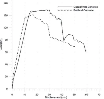
Figure 4 shows loading vs. displacement curves of the beams for both concretes. GeoBeam showed a maximum failure load of 131.7 kN (maximum bending moment, Mu = 48.9 kN.m), while the Refbeam reached 121.4 kN (Mu = 45.1 kN.m). The cracking loads were estimated as 17.1 kN (cracking bending moment, Mcr = 6.9 kN.m) and 20.4 kN (Mcr = 8.1 kN.m), respectively, for the Geo -Beam and Ref-Beam. The maximum displacement at service load
(L/250, NBR 6118) [22] was 77.7 kN (Moment at L/250 - M(L/250) = 29.1 kN.m) for the GeoBeam, while it was equal to 98.9 kN (M(L/250) = 36.9 kN.m) for the RefBeam.
The plasticity load was 127.0 kN (plasticity moment, Mp = 47.2 kN.m) and 116.2 kN (Mp = 43.2 kN.m) for the GeoBeam and Ref -Beam, respectively. It is important to highlight here that the failure
load was 8% greater for the geopolymer concrete beam. The maxi
-mum displacement at failure load was equal to 27.6 mm, while for plasticity load was 14.4 mm, which results in an overall ductility
factor of 1.92 for the GeoBeam. For the RefBeam, the maximum
displacement at failure load was 16.5 mm and for plasticity load was 10.4 mm, which results in an overall ductility factor of 1.59.
Figure 5 shows the elastic line obtained by using the three LVDTs.
Taken together, these results revealed that the GeoBeam pres-ents higher plastic deformation (see Fig. 4), leading to higher ductility. This behavior has been observed by other researchers
when evaluating the ductility of geopolymer cement composites with fibers [31]. The geopolymer concrete can support higher de
-formation without failure since it shows higher resistance to crack
propagation or higher tenacity. This is revealed for the GeoBeam in
the plastic regime (Fig. 4). Despite less rigid than Refbeam, differ -ences in the elastic regime are not very high, i.e. similar behavior in the elastic regime.
Figure 6 presents the specific deformation of the steel (measured
Figure 4
Load vs vertical displacement curves of the tested
beams, obtained by using the LVDTs
Figure 5
Vertical displacement along the beams length,
measured by the LVDTs during the loading test
Figure 6
Structural analysis of composite metakaolin-based geopolymer concrete
at the base of the beam) and of the concrete (evaluated on the
top of the beam), upon loading in the flexural tensile mode. The deformation at maximum load is rather similar for the two con
-cretes: geopolymer = 2.77%; Portland cement = 2.78%. This is
another evidence of the suitability of the geopolymer concrete as a substitute of Portland concrete for selected structural applications.
Complementarily, the curvatures “f” of the beams, measured upon
charging until the plasticity loads were equal to 2.02x10⁻⁵ rad/mm
and 2.28x10⁻⁵ rad/mm for the RefBeam and GeoBeam, respec-tively (Fig. 7), which shows a rotation capacity higher than 11% for the GeoBeam before the plasticity moment compared with the RefBeam. Figure (8a) and (8b) shows the behavior of the beams with respect to cracking after rupture, showing a small decrease of
the cracking for the geopolymer concrete.
In general, the mechanical behavior of the geopolymer concrete makes it a potential candidate to be applied to structural elements. This concrete has higher bond on steel-concrete interface,
ductil-ity and toughness, which improved the structural performance of the beam when compared to the Portland cement concrete beam. Another research demonstrate that fly ash-based geopolymer con -crete has excellent potential for applications in the precast industry [33]. Therefore, there is a great potential for geopolymer concrete
to be cast in situ [34]. However, more experimental tests, involving numerous variables that influence the execution of structures, so
that this material can be used safely.
3.3 Analysis using Finite Element Method (FEM)
The experimental results were also compared to a Finite Ele -ment (FE) nonlinear numerical model, presented in Figure 9. Because of symmetry, only half structure is studied. Both
geo-metrical and physical nonlinearities were taken into account. The steel bars and the concrete were modeled using quadratic
truss elements and quadratic plane stress elements,
respec-tively. The support was modeled using a 75 cm length zone composed by rough contact elements, which prevent horizon -tal slippage, and an elastic basis (the material of the support
was assumed elastic since we are not interested in the plastic
response of this part of the structure). The load was applied in
a 10 cm length zone in order to prevent stress concentrations.
Besides, perfect bond between steel bars and the concrete is assumed (this assumption was observed accurate enough in this case). The properties of the steel and the concrete were the
ones obtained in the mechanical characterization experiments. Constitutive behavior of the steel assumes that yielding occurs
at 597 MPa and the ultimate stress is 747 MPa. Constitutive
behavior of the concrete is made using a smeared crack model.
The necessary parameters that were not measured in this work (e.g. concrete response in tension, Poisson’s coefficient) were
Figure 7
Moment vs curvature curves measured for the
tested beams
Figure 9
Numerical model
Figure 8
taken as standard values presented by [35]. The positive (ten-sile) and negative (compressive) longitudinal plastic strains are
presented in Figure 10. We note that the lower part of the struc
-ture presents tensile plastic strains, while the upper part and a
small region close to the support present compressive plastic
strains. These results agree with experiments (see Figure 8a), since the concrete was crushed in the upper part of the beam (compressed beyond its resistance). The deflection at mid-span
is presented in Figure 11. The ultimate resistance obtained
(136.5kN) and the deflection response obtained also indicate an agreement between the experiments and the numerical model.
4. Conclusions
This research analyzed the structural behavior of a geopolymer concrete beam and compared its results to a cement Portland
beam. This analysis began with the characterization of the me -chanical behavior of the geopolymer concrete. Then, the structural
analysis of the beam with different bonding materials was investi
-gated by a 4 point bending test. Finally, a non-linear finite element model of the geopolymer beam was built using the experimental
data acquired in the geopolymer concrete experiments and its
re-sults were compared to the experimental ones.
The characterization of the mechanical properties of the
geopoly-mer concrete showed that it has better steel-to-concrete bonding, higher compressive strength at 28 days and lower rigidity than the
Portland concrete. The main results of the analysis of the structural
behavior were:
n the geopolymer concrete beam is more ductile: ductility
coef-ficient of 1.92 of the GeoBeam, while the Refbeam was 1.59;
n the geopolymer concrete beam reached higher maximum failure
load and plasticity load than the Portland concrete structure;
n the geopolymer concrete beam presented higher toughness than the conventional structure.
The finite element model generated with the data from the me -chanical characterization of the geopolymer concrete presented
reasonable results since the numerical results agreed with the ex -perimental ones.
From the experimental tests carried out on two prototype beams, it was possible to show the potential of the geopolymer concrete for application in structures. The tested beam - more than two years old - is exposed to the external environment, with no signs of leaching or other deterioration. Also, two more beams were test -ed, in reduced scale, resulting in the same behavior. Despite all manufacturing limitations for applying geopolymer concrete, it is a
Figure 10
Longitudinal plastic strains
Figure 11
Structural analysis of composite metakaolin-based geopolymer concrete
material with promising performance, which uses low cost raw ma
-terials and industrial waste. Acknowledgements
The authors gratefully acknowledge the Conselho Nacional de
De-senvolvimento Científico e Tecnológico (CNPq) for providing the
financial support for this research (grant number 443573/2014-0
and 302268/2016-2).
5. References
[1] J.L. Provis, A. Palomo, C. Shi, Advances in understanding alkali-activated materials, Cement and Concrete Research 78 (2015) 110-125.
[2] M.C.G. Juenger, F. Winnefeld, J.L. Provis, J. Ideker, Advanc -es in alternative cementitious binders, Cem Concr R-es. 41 (2011) 1232–1243.
[3] A. Rashad, Alkali-activated metakaolin: A short guide for civil
Engineer - An overview, Construction and Building Materials
41 (2013) 751-765.
[4] K. Komnitsas, D. Zaharaki, Geopolymerisation: a review and prospects for the minerals industry, Miner Eng. 20 (2007)
1261–1277.
[5] P. Duxson, Geopolymer technology: the current state of the
art, J Mater Sci. 42 (2007) 2917–2933.
[6] M. Ozel, Cost analysis for optimum thicknesses and environ
-mental impacts of different insulation materials, Energy and
Buildings 49 (2012) 552–559.
[7] Z. Pan, J.G. Sanjayan, B.V. Rangan, An investigation of the mechanisms for strength gain or loss of geopolymer mortar
after exposure to elevated temperature, Journal of Materials
Science 44 (2009) 1873–1880.
[8] F. Pacheco-Torgal, Z. Abdollahnejad, A.F. Camões, M. Jam -shidi, Y. Ding, Durability of alkali-activated binders: A clear advantage over Portland cement or an unproven issue?,
Construction and Building Materials 30 (2012) 400-405. [9] R. Chen, S. Ahmari, L. Zhang, Utilization of sweet sorghum
fiber to reinforce fly ash-based geopolymer, Journal of Mate -rials Science 49 (2014) 2548-2558.
[10] J. Davidovits, Geopolymers: inorganic polymeric new materi -als, J Therm Anal. 37 (1991) 1633-1656.
[11] A. Palomo, M. Grutzek, M. Blanco, Alkali-activated fly ashes:
A cement for the future, Cement and Concrete Research 29 (1999) 1323-1331.
[12] J.E. Oh, P.J.M. Monteiro, S.S. Jun, S. Choi, S.M. Clark, The
evolution of strength and crystalline phases for
alkali-acti-vated ground blast furnace slag and fly ash-based geopoly -mers, Cement and Concrete Research 40 (2010) 189-196.
[13] S.K. Nath, S. Kumar, Influence of iron making slags on strength and microstructure of fly ash geopolymer, Construc
-tion and Building Materials 38 (2013) 924-930.
[14] P. Sukmak, S. Horpibulsuk, S-L. Shen, Strength
develop-ment in clay–fly ash geopolymer, Construction and Building Materials 40 (2013) 566–574.
[15] V. Zivica, S. Balkovic, M. Drabik, Properties of metakaolin
geopolymer hardened paste prepared by high-pressure
compaction, Construction and Building Materials 25 (2011)
2206-2213.
[16] C. Li, H. Sun, L. Li, A review: The comparison between
alkali-activated slag (Si+Ca) and metakaolin (Si+Al) cements, Ce-ment and Concrete Research 40 (2010) 1341-1349.
[17] I. García-Lodeiro, A. Fernándes-Jiménez, A. Palomo,
Alkali-activated based concrete. In: F. Pacheco-Torgal, S. Jalali,
J.A. Labrincha, V.M. John, editors. Eco-efficient concrete.
UK: Woodhead Publishing Limited (2013) p. 26–41. [18] X. Guo, H. Shi, W.A. Dick, Compressive strength and
mi-crostructural characteristics of class C fly ash geopolymer.
Cement & Concrete Composites 32 (2010) 142–147.
[19] S. Songpiriyakij, T. Kubprasit, C. Jaturapitakkul, P. Chindaprasirt, Compressive strength and degree of reaction
of biomass- and fly ash-based geopolymer, Construction and Building Materials 24 (2010) 236–240.
[20] T-H Ueng, S.-J Lyu, H.-W Chu, H.-H Lee, T-T Wang, Ad-hesion at interface of geopolymer and cement mortar un-der compression: An experimental study. Construction and
Building Materials 35 (2012) 204–210.
[21] C.H. Un, J.G. Sanjayan, R. San Nicolas, J.S.J. van Deventer,
Predictions of long-term deflection of geopolymer concrete beams, Construction and Building Materials 94 (2015) 10–19. [22] G.B. Maranan, A.C. Manalo, B. Benmokrane, W. Karunas
-ena, P. Mendis, Evaluation of the flexural strength and ser
-viceability of geopolymer concrete beams reinforced with glass-fibre-reinforced polymer (GFRP) bars, Engineering
Structures 101 (2015) 529–541.
[23] F. Pelisser, E.L. Guerrino, M. Menger, M.D. Michel, J.A. Labrincha, Micromechanical characterization of metakaolin-based geopolymers, Construction and Building Materials 49
(2013) 547–553.
[24] NBR 6118 (2014). Project of Concrete Structures; Brazilian
Association of Technical Standards: Rio de Janeiro, Brazil. (in Portuguese)
[25] NBR 7215 (1997). Portland cement: Compressive strength;
Brazilian Association of Technical Standards: Rio de Janeiro, Brazil. (in Portuguese)
[26] ASTM C-1231 (2010). Standard practice for use of unbonded
caps in determination of compressive strength of hardened
concrete cylinders. ASTM International, West Conshohock -en, PA, USA.
[27] NBR 8522 (2017). Concrete - Determination of elastic
modu-lus and the stress-strain curve; Brazilian Association of Tech -nical Standards: Rio de Janeiro, Brazil. (in Portuguese) [28] B.V. Silva, Proposal of an bond test for the technological
control of the compressive strength of concrete, Ph.D. The-sis (Civil Engineering), Federal University of Rio Grande do Sul, Porto Alegre, Brazil, 2014. (in Portuguese)
[29] International Organization for Standardization. ISO 6892-1
(2009). Metallic materials - Tensile testing - Part 1: Method
of test at room temperature.
[30] COMITÉ EURO-INTERNATIONAL DU BÉTON. RILEM/
CEB/FIP RC6 (1983). Bond test for reinforcing steel - 1 - pull-out test. Paris: CEB.
[31] B. Nematollahi, J. Sanjayan, F.U.A. Shaikh, Comparative
deflection hardening behavior of short fiber reinforced geo
-polymer composites. Construction and Building Materials 70
[32] M. S. Reddy, P. Dinakar, B. Hanumantha Rao, A review of the influence of source material’s oxide composition on the compressive strength of geopolymer concrete, Microporous and Mesoporous Materials 234 (2016) 12-23.
[33] D. Sumajouw, D. Hardjito, S. Wallah, B. Rangan, Fly
ash-based geopolymer concrete: study of slender reinforced
col-umns, Journal of Materials Science 42 (2007) 3124-3130. [34] M. Reed, W. Lokuge, W. Karunasena, Fibre-reinforced geo
-polymer concrete with ambient curing for in situ applications, Journal of Materials Science 49 (2014) 4297-4304.