This paper presents the structural behavior of six reinforced concrete pile caps in rectangular arrangement, considering the ground deformability of pile support, different concrete strengths with square or rectangular cross section of column under central load. For this purpose, the analysis
emphasizes a strut and tie method design and a three-dimensional numerical using the inite element method. So, the stress low coniguration
and the formation of struts were seen in perspective. How much deformable is the ground, more uniform are the reactions distribution observed
be-tween the piles. The column cross section inluenced the coniguration of the connecting struts. The concrete strength variation had more inluence
in the pile caps strength than the stiffness. The analytical method has shown compatibility which obtained from the numerical simulation results.
Keywords: reinforced concrete; six pile caps; strut and tie method.
Este artigo analisa o comportamento estrutural de blocos de concreto armado sobre seis estacas dispostas em arranjo retangular. Considerou--se a deformabilidade do solo de apoio das estacas, diferentes resistências para o concreto e pilares com seções transversais quadradas e retangulares, solicitados por força centrada. O dimensionamento foi feito por um modelo de bielas e tirantes. Realizou-se análise numérica
tridimensional por meio do método dos elementos initos. A coniguração do luxo de tensões e a formação das bielas foram analisadas em perspectiva. Observou-se que quanto mais deformável for o solo, mais uniformes são as distribuições das reações entre as estacas. A seção transversal do pilar inluenciou na coniguração das bielas. A variação da resistência do concreto teve maior inluência na resistência dos blo
-cos do que na rigidez. O método analítico utilizado apresentou compatibilidade com os resultados obtidos na simulação numérica.
Palavras-chave: concreto armado; blocos sobre seis estacas; método de bielas e tirantes.
Six pile caps reinforced concrete: numerical simulation
and design by the strut and tie method
Blocos de concreto armado sobre seis estacas:
simulação numérica e dimensionamento pelo método
de bielas e tirantes
D. S. OLIVEIRA a [email protected]
R. BARROS a [email protected]
J. S. GIONGO a [email protected]
a Departamento de Engenharia de Estruturas, Escola de Engenharia de São Carlos, Universidade de São Paulo, São Carlos, SP, Brasil.
Abstract
1. Introdution
Pile caps are structural foundation elements that transfer the su-perstructure load to the piles. Their type depends on the load on the column base, the geotechnical capacity of the ground and the available building conditions and pile strength. For pile caps con-taining three or four piles, it is common to adopt triangle arrange-ment or square arrangearrange-ment for piles, respectively. However, in pile caps with many piles, the piles are equally spaced to create a rectangular base, generating situations in which the distance be-tween the piles to the axis column is not the same.
Pile caps are special elements because their structural behavior does not follow hypothesis that sections remains plane after the
structure deformation. Although they are dificult to analyze while
on operation, their fundamental for the superstructure security, so it is important to know their real behavior. In situations in which the piles are not equally spaced in relation to the column axis, as the pile caps type analyzed here, the structural behavior is more complex and little known . The pile reactions may not have uniform values, because they depend on the pile cap stiffness, the ground and piles deformability.
The irst researches in the area focused on experimental analy
-sis and were crucial to the development of the irst analytical
methods, such as Blévot & Frémy [1] study. However, even with the increase of the years, most researches focus analysis of pile caps with a few number of piles, as the Delalibera & Giongo [2] and Miguel & Giongo [3], which analyzed pile caps contain-ing on two and three piles, respectively. Only few studies have reported on experimental analyses of pile caps with more than four piles, focusing on piles not equally spaced from the column. Among such studies we can highlight that of Adebar et al. [4], who observed, in four and six pile caps, that reactions distribu-tion between the piles show no uniform values, because the nearest piles from the columns receiving higher load than the other ones. However, the authors did not consider the ground deformability for the piles support.
With powerful computers and the Finite Element Method is pos-sible to analyze models by numerical simulation, introducing more
complex situations, such as ground deformability for the piles
sup-port that is a dificult situation to do experimentally.
Ramos & Giongo [5] analyzed pile caps over ten piles by numerical simulation and found that the piles closer to the column were the most loaded ones, even considering the ground deformability for
piles support. They also observed that methods that consider lex -ural behavior, with shear force and bending moment design, in ref-erence sections, were not compatible with the pile caps behavior, nevertheless they did not present an appropriate model for design. The analytical methods for pile caps design available in the literature follow basically two different ways. The first and more accepted in the technical environment is the strut and tie method, which represents the stresses flow idealized by the truss model. The internal structure consists of compressed and tensile bars, which are the strut and ties, interconnected by nodes. This method has become more employed after Blévot & Frémy [1] research, but regarding pile caps with many piles, the literature lacks studies that show the struts configuration and criteria to define strength of struts. Therefore, it is still com-mon to use a second way to design those types of pile caps. It consists in associating the behavior of the pile caps with the bending theory of beams. Although studies have shown that this option is not so compatible with pile caps structural behavior. Analytical methods based on this principle are still used because they are practical and easy to understand. As the method presented in Bulletin number 73 of the CEB- FIP [6] that consists of computation of bending moment and shear force in reference sections.
ABNT NBR 6118:2007 [7] classiies blocks as rigid or lexible and
considers the pile caps special elements, which are characterized by a behavior that does not follow the hypothesis that the cross sections remain planes after structure become deformed because they are not long enough to dissipate located disturbances. For a pile caps design, the Brazilian standard recommends the strut and tie method as the best option to represent the stress distribution, more appropriately. Despite the recommendation, the Brazilian regulation does not provide a clear guide for pile caps design. Bra-zilian technical lacks researches about pile caps, especially about pile caps with many piles and when piles are not equally spaced to the column axis.
This paper reports a structural behavior analysis of pile caps con-gaing six piles, arranged in two rows of three piles. Presents an analytical method based on the strut and tie method and evaluates
the parameters that inluences structural behavior of this type of pile caps though the inite element method.
2. Pile caps design by analytical models
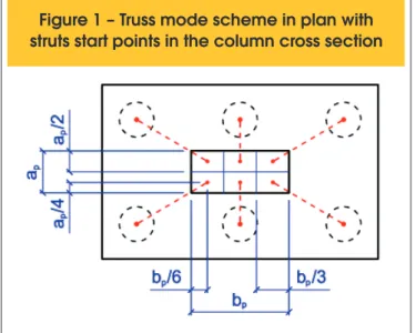
For design of the six pile caps Andrade [8] recommendations were considered, as it follows similar criteria to those proposed by Blévot & Frémy [1] and Machado [9]. However, Andrade [8] indicate pa-rameters for the pile caps with any number of piles, different ar-rangements for the piles and square or rectangular cross section for the column. According to the author, in general the cross sec-tion columns are not square, but rectangular and very elongated. For very elongated sections it is more correct to consider the struts position near the column base, which must be determined in
accor-dance with the engineer’s analysis in each speciic situation. The
struts positions scheme near the column is shown in Figure [1].
Rst - Tensile force in the tie.
3. Properties of the pile caps analyzed
The structural behavior of the six pile caps was analyzed con-sidering the following parameters variation: column cross sec-tion, ground deformability for the piles support and compression strength of the concrete.
The geometric parameters were deined based on an example of
a building project, just to set the magnitude of the pile cap dimen-sions and the adjacent column cross-sectional area. Piles with 60 cm of diameter (continuous helix piles) were considered. They have spaced each other by a distance equal a three times their diameter. The distance between the tangent plan of the outer pile to the pile cap ends was equal to 30 cm. The pile caps plan dimen-sions are shown in Figure [3].
Three different column cross sections shape were considered in the analysis: square (
b
p=
a
p); rectangular slightly elongated (b
p=
4
⋅
a
p), rectangular very elongated (b
p=
8
⋅
a
p). Fur-thermore, the cross-sectional area was kept constant and themagnitude of the value was deined based on the pile caps taken
as examples, as previously mentioned. Table [1] shows the cross sections of the dimensions for the columns.
The height was deined considering that the angle between the
strut and tie relative to the farthest pile to column axes is 40°. Each strut is located at the midpoint of each portion columns area, as shown in Figure [1]. Nonetheless, in cases in which there was a variation in the column cross section, the struts became different of 40°, as shown in Table [1]. For all pile caps,
the heights obtained satisied the rigid criteria indicated in Bul -letin number 73 of the CEB- FIP [6] and ABNT NBR 6118:2007 [7]. The piles were considered 10 cm embedded in pile cap. Reinforcement with 25 mm diameter was considered and the lower face of the reinforcement were placed 2 cm above the top face of the pile.
Pile caps with tree concrete strengths (25 , 30 and 35 MPa) were analyzed. The yield strength for the reinforcement was considered equal to 500 MPa.
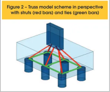
The design was based on the strut and tie model shown in Figure [2] for the six pile caps. Was computed the required reinforcement and checked the compressive stresses in the ends of the struts near the column and piles. Andrade [8] recommends that the angles between struts and ties should be higher than 40º and less than 55º.
The concrete stresses for the struts are computed by equations [1] and [2], always considering the angle for the less inclined strut. Limit compressive stress in struts near the column:
(1)
cdp p
sd p
cb
A
sen
f
F
£
a
×
×
q
×
=
s
0
,
85
²
,Limit compressive stress in struts near the piles:
(2)
cde e
sd e
cb
A
sen
f
F
£
a
×
×
q
×
×
=
s
0
,
85
²
6
,
where:
e
A
- Pile cross-sectional area;p
A
- Column cross-sectional area;F
sd - Normal force from the column;f
cd - Concrete compressive strength;θ
- Inclination strut angle;p
α
- Adjust coeficient equal 2.6 (indicated by Andrade [8]);e
α
- Adjust coeficient equal 1.0 (indicated by Andrade [8]); The areas of reinforcements are calculated by the equation [3].(3)
ydstd st
f
R
A
=
where:
fyd - Steel yielding strength;
Figure 2 – Truss model scheme in perspective
with struts (red bars) and ties (green bars)
ers perfect adhesion between the reinforcement and concrete. For the column reinforcement, was adopted area equal to 3% of the columns cross section area and reinforcements with diameter equal to 25 mm distributed on the column perimeter. Stirrups of 8 mm diameter and spaced 20 cm each other were also placed.
4. Aspects of inite element
numerical simulation
The inite element models were simulated using DIANA software [10].
To simulate the physical nonlinearity of the concrete structural behav-ior, the total strain model of the smeared cracking was considered. It treats the concrete as a continuous material and retains the original mesh discretization even with the appearing of crack. The parabolic model was considered for the concrete compression behavior and for tensile behavior was used the exponential model, available in DIANA
software [10]. To account the beneicial effect of lateral coninement
and a strength reduction, because of lateral cracking, was used the model proposed by Vecchio and Collins [11] and available in DIANA
software [10]. The inelastic process zone was deined by the length
of the cracks band, which was calculated from the cubic root of the The ground deformability was considered by elastic springs,
locat-ed in piles base. Four cases were examinlocat-ed: a rigid pile support, considered the most unfavorable for the pile cap, and three other situations that considered piles supported by elastic springs with
the following coeficients: 300 kN/mm, 600 kN/mm and 900 kN/ mm. For more information about the spring coeficients obtained
considering the piles settlement, consult Oliveira [14].
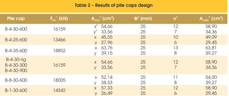
Eight different pile caps were obtained with the parameters variation
mentioned above. The irst pile cap (Table [1]) was considered the reference pile cap. The remaining ones were deined by parameters
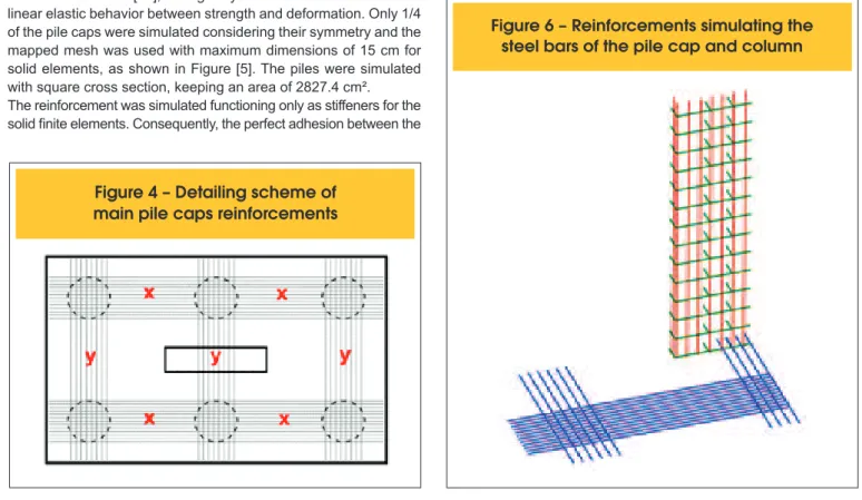
variation from the reference pile cap and are bolded in Table [1]. The results of the pile caps design are provided in Table [2]. The pile caps were designed always considering the uniform distribution of the piles reactions, independently of the ground deformability. Figure [4] shows positions for the main reinforcements computed in Table [2]. The reinforcements were detailed as recommended by ABNT NBR 6118:2007 [7], which indicates that tensile stresses are concen-trated mainly on connecting lines between piles, in a band of width equal to 1.2 times the pile diameter.
There was neither anchoring check for reinforcements nor hooks
at their ends, because the numerical inite element model consid
-Table 1 – Parameters evaluated on six pile caps
Pile cap
b (cm)
pa (cm)
p2
h (cm)
f (MPa)
ckk (kN/mm)
ϴ
(degree)
1
B-4-30-600
B-4-25-600
B-4-35-600
B-4-30-rig
B-4-30-300
B-4-30-900
B-8-30-600
B-1-30-600
143
143
144
143
143
143
200
71
35
35
36
35
35
35
25
71
145
145
145
145
145
145
145
145
30
25
35
30
30
30
30
30
600
600
600
Rigid support
300
900
600
600
40
40
40
40
40
40
43
37
1B pile cap or Bloco in Portuguese, 4 relation between the lowest side (a ) and biggest side (b ) of columns cross section, p p
2
30 concrete strength, 600 spring coef ficient; Pile cap height.
Table 2 – Results of pile caps design
Pile cap
F (kN)
1teo
2 2
A
s,teo(cm )
3
Φ
(mm)
n
4A
5(cm )
2s,effe
B-4-30-600
B-4-25-600
B-4-35-600
B-4-30-rig
B-4-30-300
B-4-30-900
B-8-30-600
B-1-30-600
16159
13466
18852
16159
18005
14342
6x
6y
x
y
x
y
x
y
x
y
25
25
25
25
25
25
25
25
25
25
12
7
10
6
13
8
11
8
12
6
58,90
34,36
49,09
29,45
63,81
39,27
54,00
39,27
58,90
29,45
54,66
33,56
45,55
27,96
63,76
39,15
x
y
54,66
33,56
25
25
12
7
58,90
34,36
52,14
38,53
57,33
26,49
1 2 3 4
Analytical pile cap strength; Analytical reinforcement; Diameters of reinforcements; Number of reinforcements;
5 6
inite element volume. The elasticity modulus, the tensile strength, the tensile fracture energy and poisson coeficient, were adopted consid -ering CEB-FIP Model Code 1990 [12] and they are show in Table [3]. The compressive fracture energy was considered equal to 50 times the tensile fracture energy, as shown in Feenstra and Borst [13]. The linear elastic model was considered for the simulation for the column and the piles concrete. With this consideration, just the pile cap will reach the ruin.
Von Mises elastoplastic model was considered for steel, with elas-ticity adopted equal 210 GPa as shown in ABNT NBR 6118:2007 [7], and the Poisson’s ratio was 0.3.
The solid inite element CHX60 available in DIANA software [10]
was used to represents the concrete. This element has quadratic
interpolation to compute the displacements. The inite element SP -2TR was used to represent springs for piles supporting available in DIANA software [10], acting only with vertical translation and
linear elastic behavior between strength and deformation. Only 1/4
of the pile caps were simulated considering their symmetry and the mapped mesh was used with maximum dimensions of 15 cm for solid elements, as shown in Figure [5]. The piles were simulated with square cross section, keeping an area of 2827.4 cm². The reinforcement was simulated functioning only as stiffeners for the
solid inite elements. Consequently, the perfect adhesion between the
reinforcement and the surrounding concrete was considered. Figure [6] shows the modeling of the pile cap and the column reinforcements. Finally, the loading was applied through displacement steps, considering just centered normal force on column top. The strategy used for solving nonlinear systems equations was the “Newton-Raphson Regular” method with convergence criterion for energy and tolerance equal to 0.01.
Figure 4 – Detailing scheme of
main pile caps reinforcements
Figure 5 – Finite elements mesh for concrete
F
igure 6 – Reinforcements simulating the
steel bars of the pile cap and column
Table 3 – Constitutive model
parameters of the concrete
Concrete
parameters
1
f (MPa)
ck25
30
35
2
G (N.mm/mm²)
f 3G (N.mm/mm²)
c 4E (MPa)
c 5f
ctm6
n
7
b
0,0699
3,3472
29180
2,6
–
–
0,0761
3,8029
31008
2,9
0,2
0,2
0,0847
4,2362
32643
3,2
–
–
1 Concrete compressive strength; Tensile fracture energy of 2 3
concrete; Compressive fracture energy of concrete;
4 5
Initial longitudinal elastic modulus of concrete; Tensile
6 7
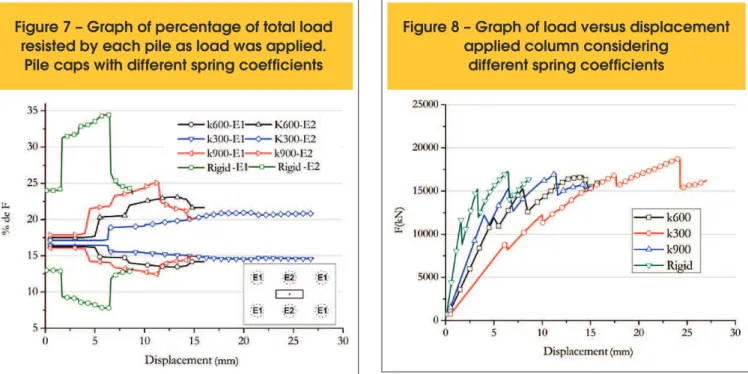
Figure 7 – Graph of percentage of total load
resisted by each pile as load was applied.
Pile caps with different spring coefficients
Figure 8 – Graph of load versus displacement
applied column considering
different spring coefficients
cements of pile caps:
(a) B-4-30-300; (b) B-4-30-600; (c) B-4-30-900; (d) B-4-30-rig. (MPa)
A
C
B
5. Results
Figure [7] shows a graph that compares the total load percentage acting
on each pile considering different values for coeficient of the springs.
For initial loading stages, the reactions remained almost uniform in the
pile cap supported on the springs, independently of spring coeficient. However, for rigid support, the reactions were signiicantly different since
the beginning of the load. With load increase, the piles, whose struts are more inclined, become more loaded than the other ones, whose struts are more slaughtered. Therefore, the higher the value of the spring
coef-icient, the worse the reactions distribution between piles.
Analyzing the graph shown in Figure [8], the obtained pile caps
strength was similar, but the pile cap with spring coeficient k = 300 kN/mm showing a small strength increase. This increase can be
attributed to a better reactions distribution among piles, provided
by springs with k = 300 kN/mm, which enable a signiicantly con -tribution of all piles to the pile cap strength. However, for other pile caps, this contribution did not occur in same proportion.
Figure [8] shows that for more deformable ground, the pile cap
have a more continuous increase in load, with a large settlement
until the ruin. The higher the spring coeficient, the lower the set -tlement in ruin. The lower the ground deformability, the more dis-continuous the pile cap behavior until ruin, which may have been caused by cracking and localized fractures. This may be occurred because the pile caps have large capacity to redistribute internal stresses and they are very statically indeterminate.
The coeficient k = 300 kN/mm enable the best reactions distribution for the pile cap, with all piles contributing with signiicant strength un
-til the pile cap ruin. Thus, is expected that for coeficient lower than k = 300 kN/mm, the reactions distribution tend to be more uniform.
Figure [9] shows that for higher ground deformability better is the tensile stresses distribution in reinforcement, with similar behavior to that considerate in strut and tie model. With the higher spring
coeficient higher is the tensile stress concentration in central re -inforcement, and this concentration was even more critical where the piles support is rigid, with the central reinforcement reaching the yield stress while tensile stresses in the other reinforcements keeping relatively small values.
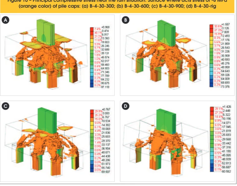
Figure [10] shows pile caps near a ruin stage. For pile caps
sup-Figure 10 – Principal compressive stress near the ruin situation. Surface where acts stress of -8 MPa
(orange color) of pile caps: (a) B-4-30-300; (b) B-4-30-600; (c) B-4-30-900; (d) B-4-30-rig
A
B
ported on springs, better are the distribution of the compressive stress forming struts for all piles. This behavior is similar to that supposed by the strut and tie model. Therefore, the lower the
spring coeficient, the better the stress distribution. However, for
rigid support occurred concentration of the compressive stress pre-dominantly for the two piles closest to column.
Regarding column cross section variation, the column cross sec-tion elongasec-tion improved the piles reacsec-tions distribusec-tion, contribut-ing to a more uniform distribution in comparison with the square cross section, as shown in the graph of Figure [11]. The elongated cross section provided a continuous behavior, while square col-umn cross section there was a series of brusquely redistributions, as the load increased.
The variation in the shape of the column cross section does not
change the pile caps strength signiicantly, displaying the same or -der of magnitude for resistance, as shown in Figure [12]. But for highly elongated columns cross section there was a small increase in strength. This can be associated to a better distribution of com-pressed stresses for the farthest piles to the column, forming more inclined struts.
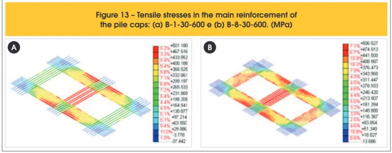
The elongation of the column cross section alters the tensile stress distribution on ties reinforcements, as can be seen by comparing Figures [13a], [13b] and [9b]. For the pile cap with square section, the tensile stresses concentrated on the reinforcement between the two middle piles. On the other hand, with the column cross section elongation tensile stresses was better distributed in all re-inforcements.
The diagrams of surfaces with same stress (see Figures [14]
through [16]) show that for all situations, the low stress has
Figure 11 – Graph of percentage of total load
resisted by each pile as load was applied.
Pile caps with different column cross sections
Figure 12 – Graph of load versus
displacement applied considering
different column cross sections
Figure 13 – Tensile stresses in the main reinforcement of
the pile caps: (a) B-1-30-600 e (b) B-8-30-600. (MPa)
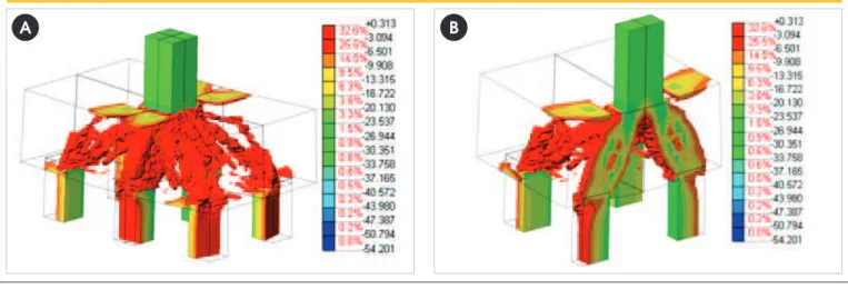
Figure 14 – Principal compressive stress. Surface where acts a stress of -6 MPa in pile cap B-1-30-600:
(a) entire pile cap and (b) vertical section. Loading stage with 10.8 mm of displacement applied
A
B
Figure 1
5 – Principal compressive stress. Surface where acts a stress of -6MPa on pile cap B-4-30-600:
(a) entire pile cap and (b) vertical section. Loading stage with 13.3 mm of displacement applied
A
B
Figure 16 – Principal compressive stress. Surface where acts a stress of -6MPa on pile cap B-8-30-600:
(a) entire pile cap (b) vertical section. Loading stage with 10.4 mm of displacement applied
observed when we compare Figure [1] with Figure [19]. Therefore, this shows the importance of considering the real columns cross section for pile caps design.
The analytical method had good approximation for the strength of the pile caps relative to the increase in concrete strength. More-over, this method proved to be easy to use, enabling the deter-mination of the truss model according to any pile caps arrange-ment and considers the real columns cross section and pile caps. However, an important aspect should be considered that is relative to struts angle. This type of pile cap do not have symmetrical ar-rangements for the piles and because of it, struts will have different angles. So, is better to consider the less inclined strut having 40°. Thereby, maybe the angles of the more inclined struts can be be-low the upper limit of 55°.
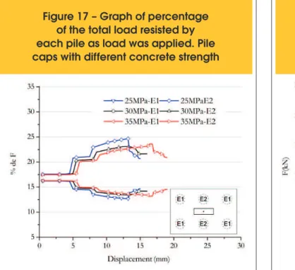
adapted to the column cross section shape. The compressive stresses trajectory accompanied the column cross section elonga-tion, enabling the formation of more inclined struts relative to the horizontal plan, starting near the ends of the column cross sec-tion. Conversely, for square columns cross section struts were less inclined to the horizontal plan. Furthermore, the columns cross section elongation enable a reduction in the concentration of the compressive stresses related to piles near the column and a redis-tribution of these stresses to other piles more distant to the column. Figure [17] shows that increasing in strength of concrete did not
improve the reactions distribution, signiicantly, for the pile caps. The inluences in reactions distributions caused by ground deform
-ability were more signiicant than the concrete strength variation.
The graph in Figure [18] shows the increase of concrete strength resulted in a pile cap strength increase. The initial portion of force versus displacement curves practically coincided in the early stag-es, diverging only for the lasts stages of load. Therewith it is clear
that the variation of concrete strength had negligible inluence in
the stiffness of this pile caps here analyzed.
In relation to the analytical method used, Table [4] shows that the criteria recommended by Andrade [8] for the strut and tie model enable a good approximation for the strength than those obtained by numerical models, for all pile caps.
The compatibility between the results obtained by analytical meth-od and by the numerical mmeth-odels was not only relative to strength
of the pile caps. Figure [15] shows that the coniguration of the compressive stresses are compatible to the struts coniguration in -dicated by Andrade [8]. The struts origins are in the contact region between column and pile cap and connect to the top of piles. Sev-eral pile caps revealed that struts have not converged to a single point at columns axis, they change with the variation of the shape
of the column cross section. This fact conirms the analytical meth -od hypothesis that considers the origins points of each strut in cen-ters of portions of areas of the column cross section. This can be
Figure 17 – Graph of percentage
of the total load resisted by
each pile as load was applied. Pile
caps with different concrete strength
Figure 1
8 – Graph of load versus
displacement applied
to the column considering
different concrete strengths
Table 4 – Comparison between numerical
and analytical models
Pile
cap
(kN)
F
teo1
F
num(kN)
F /F
num(kN)
teoB-4-30-600
B-4-25-600
B-4-35-600
B-4-30-rig
B-4-30-300
B-4-30-900
B-8-30-600
B-1-30-600
16159
13466
18852
16159
16159
16159
18005
14342
16744
14929
20865
17247
18775
17019
19195
16183
1,036
1,109
1,107
1,067
1,162
1,053
1,066
1,128
1
Oliveira [14] analyzed the pile caps structural behavior with six
and also ive pile arrangement. This author found compatibility
of results obtained by Andrade [8] and by numerical models and analyzed pile caps with different column cross sections, different heights and irregular piles arrangement.
6. Conclusions
The results show that the ground deformability for piles support,
represented by elastic springs, signiicantly inluences the structur -al behavior of the pile caps here an-alyzed, especi-ally regarding the
distribution of pile reactions. This inluence was mainly observed in compressive stresses coniguration and tensile stress distribution
on reinforcement. These results sustain the hypothesis commonly adopted for design that uniform distribution for pile reactions may not be appropriate for situations where the ground is very rigid. Therefore, is better to do soil structure interaction study to check the hypothesis that considers uniform reactions is a reasonable approximation. Otherwise, should be necessary design the pile cap considering non uniform distribution reactions for the piles. In any case, ground deformability did not affect the pile caps
strength signiicantly because of the ability of these pile caps to re -distribute internal stresses. Although the analytical method showed good strength approximation for all cases, the distribution pile
re-actions should be analyzed for each speciic case.
The concrete strength increase enabled a pile cap strength gain, which is consistent with the hypothesis of analytical methods. However, varying the concrete strength did not alter the pile caps
stiffness signiicantly.
Concerning the column cross section variation, the struts conigu
-ration were modiied by the cross section elongation. Furthermore,
consider the struts origins in the center of portions columns cross sections relative to each pile area is a reasonable approximation. Andrade [8] criteria enabled a pile caps strength prediction with good
approximation of the numerical simulation results. There was also
com-patibility between the strut and tie model compressive stress conigura -tion observed and the tensile stresses distribu-tion in the reinforcements.
7. Acknowledgments
The authors would like to acknowledge CAPES and CNPq for i -nancial support and the Department of Structural Engineering,
School of Engineering of São Carlos, University of São Paulo.
8. References
[01] BLÉVOT, J. L.; FRÉMY, R. Semelles sur Pieux. Annales de L’Institut Technique du Batiment et des Travaux Publics. v. 20, n. 230, p. 223-295, févr. 1967.
[02] DELALIBERA, R. G.; GIONGO, J. S. Inluência das dimen
-sões da seção transversal do pilar e da excentricidade da força de compressão no comportamento estrutural de blo -cos sobre duas estacas. IBRACON Structures and Materials Journal. v. 2, n. 4, P. 316-325. dez. 2009.
[03] MIGUEL, M. G. ; GIONGO, J. S. Análise experimental e nu -mérica de blocos sobre três estacas. Cadernos de
Engen-haria de Estruturas, São Carlos, v. 7, n. 28, p. 1-20. 2005. [04] ADEBAR, P.; KUCHMA, D.; COLLINS, M. P.Strut-and-tie
models for design of pile caps: an experimental study. ACI
Structural Journal, v. 87, n.1, p. 81-92, jan./ feb. 1990. [05] RAMOS, F. A. C.; GIONGO, J. S. Análise das reações nas
estacas em blocos com pilares submetidos à ação de força centrada e excêntrica considerando a interação solo-estru
-tura. Cadernos de Engenharia de Estruturas, São Carlos, v.
11, n. 50, p. 155-170, 2009.
[06] COMITÉ EUROPÉEN DU BÉTON. CEB-FIP. Recommanda -tions particulières au calculet à l’exécution dê ssemelles de fondation. Bulletin D’Information, Paris, v. 4, n.73, p. 27-35. 1970.
[07] ASSOCIAÇÃO BRASILEIRA DE NORMAS TÉCNICAS. NBR 6118: Projeto de estruturas de concreto - Procedimen-to. Rio de Janeiro. 2007.
[08] ANDRADE, J. R. L. Dimensionamento de elementos estru-turais de fundações. Departamento de Estruturas, Escola
de Engenharia de São Carlos, Universidade de São Paulo. SET-EESC-USP. São Carlos. 1989.
[09] MACHADO, C. P. Fundações. Escola Politécnica da Univer
-sidade de São Paulo - EPUSP, São Paulo. 1985.
[10] DIANA. DIANA Finite Element Analysis. User’s Manual Re -lease Notes. Re-lease 9.4.4.TNO DIANA BV, Delft, Nether-land. 2012.
[11] VECCHIO, F. J.; COLLINS, M. P. Compression response of cracker reinforced concrete. ASCE Journal of Strucutral En-gineering, Vol. 119, n. 12, p. 3590-3610. 1993.
[12] COMITE EURO-INTERNACIONAL DU BÉTON. CEB-FIP: Mod -el code 1990. Bulletin D’Information, Paris, n. 203-205. 1993. [13] FEENSTRA, P. H.; BORST, R. Aspects of Robust
Compu-tational Modeling for Plain and Reinforced Concrete. Heron, v.38, n.04, Delft, Netherlands, p.3-76. 1993.
[14] OLIVEIRA, D. S. Análise do comportamento estrutural de blocos de concreto armado sobre cinco e seis estacas.
Dis-sertação (Mestrado) – Escola de Engenharia de São Carlos, Universidade de São Paulo. 2013.