HSMM: Hard Switching Memristor Model
Wanlong Chen,
Member, IAENG,
Xiao Yang, and Frank Z.Wang
Abstract—The memristor (short for memory resistor) was reasoned from symmetry arguments in 1971 by Leon Chua as the fourth fundamental circuit element. Memristors are novel nano-devices, which could be used in many applications, such as memories and neural networks. Among the emerging nanotechnologies options, memristors have become a very promising candidate during post-CMOS times because of its better nonvolatility, shorter switching time, higher capacity and lower power consumption and more compatibility with CMOS. A new memristor model has been developed and introduced in this paper. Different memristive systems may require different memristor models, which are sufficiently accurate and simple for computing. Hard Switching Memristor Model (HSMM) could be fit to specific memristive system and particular chemical materials. In some cases, HSMM is more authentic than the existing memristor models.
Index Terms—Memristor, simulation, memristive system, modelling, window function, model, nano-device.
I. INTRODUCTION
Leon Ong Chua, an IEEE Fellow and a professor in the electrical engineering and computer sciences department at the University of California (Berkeley), with his seminal paper challenged the well established perception of tradi-tional electronics which consist of three fundamental circuit elements: the capacitor, the resistor and the inductor [1]. The fundamental circuit elements contain four types of variables: flux (ϕ), charge (q), voltage (v) and current (i). Theoretically, a relation would exist between each pair of the variables, as a result, in regarding with the symmetry arguments that there should be a total of 6 relations between those 4 variables, however, only 5 had been identified [2]. Therefore, Chua suggested there should exist a fourth element. He named the fourth element as memristor that holds a relationship between flux and charge and mathematically proved its rationality. 37 years after he predicted the memristor existence, a working solid-state memristor based on a nanoscale thin-film of titanium dioxide was created by a team leaded by Williams at Hewlett Packard [3], [4].
In order to improve the computing performance, an out-standing technological progress has been driven through some inventions of integrated circuits and the transistor. Among several emerging technologies, the memristor has be-come one of the most promising candidates in building a bet-ter storage structure with higher capacity and more efficient performance. Memristor and memristive system could be a very suitable technology for such demanding procedures and all the requirements that were mentioned could be provided by computing technologies in an efficient and energy-saving way. Memristor offers non-volatility, fast switching, low
Manuscript received July 03, 2014; revised August 12, 2014. This work was supported in part by the University of Kent under the student research grant.
Wanlong Chen, Xiao Yang and Frank Z.Wang are with the School of Computing, University of Kent, Canterbury, Kent, UK, CT2 7NZ , e-mail: (W.Chen@kent.ac.uk).
energy cost and high density, in particular, memristors can be scaled down to less than 10 nm [5]. Memristors have been widely used in many applications, such as storage elements in the content addressable memory and synapses in neural network [6]–[11]. HP currently announces that they will pop 100TB memristor drives into their product in five years [12]. The memristor behaves like a resistor with the function which could remember the history of its current meanwhile exhibits many peculiar unconventional non-linear features [13]. These interesting distinctive characteristics have been developed and designed to a number of models for different applications [3], [14]–[22]. Modelling the memristor is important to design memristive systems, memristor circuits and analyse their performance.
In this paper, we present a new memristor model which is the hard switching memristor model (HSMM), that could offer more flexible and accurate simulation results. As for the organization of the paper, in Section II, we will review the HP memristor model. Then we will describe our new memristor model, the hard switching model, which includes a controllable parameter for appropriately adjusting and refining the model to match certain chemical materials or specific memristive systems in Section III. Section IV will provide the simulation results and discussions regarding the performance. Finally, the conclusion will be drawn in Section V.
II. HP MEMRISTORMODEL
In 2008, the initial fabrication of solid-state memristor device was developed by a research team at HP labs. HP memristors can be used into devices called crossbar latches [3].
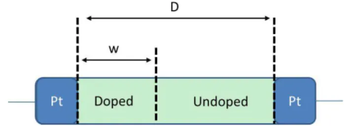
Fig. 1. HP memristor model.
A thin film of titanium dioxide (T iO2) is used in HP Memristor Model (shown in Fig. 1), because the structure of these thin-film titanium dioxide memristors are set to become a stoichiometric layer of titanium dioxide (low resistance
RON) and an oxygen deficient layer (high resistanceROF F) sandwiched between two platinum electrodes [3], [4]. D is the length of the device and w is the length of the doped region. The functions of the HP memristor model are given by
v(t) = (RON
w(t)
D ) +ROF F(1− w(t)
D ))i(t) (1)
Proceedings of the World Congress on Engineering and Computer Science 2014 Vol I WCECS 2014, 22-24 October, 2014, San Francisco, USA
ISBN: 978-988-19252-0-6
ISSN: 2078-0958 (Print); ISSN: 2078-0966 (Online)
dw(t)
dt =µV RON
D i(t) (2)
whereµV is the ion mobility,v(t)is the voltage that applied to the memristor, i(t) is the corresponding current of the device andw(t)is limited in the range of the device between
0 andD.
III. HSMM: HARDSWITCHINGMEMRISTORMODEL
In order to model the non-linear drift of the memristor , a window function f(w) is multiplied on the right-hand side of equation (2) [3], therefore
dw(t)
dt =µV RON
D i(t)×f(w) (3)
A new window function is proposed in this paper to model the memristor in the following form:
f(w) =
w3
a3 a≥ w≥0
(1−w)3
(1−a)3 1≥ w > a
(4)
where0< a <1.
The HSMM window function has two sub-domains [0,a] and (a, 1] which constitute the whole domain range [0, 1]. The illustration of the HSMM window function is shown in Fig. 2. One advantage of using this HSMM window function is that we can set different a based on different memristor materials or specific memristor models requirements.
Fig. 2. Plot of our proposed window functionf(w)with different values ofa.
In this paper, we assume that D = 1,Ron = 1,µV = 1 and when t= 0 ,q(0) = 0,w(q= 0) =w0.
Since
i(t) =dq(t)
dt (5)
which yields the following formula for w(q)
w(q) =
1
q
−2q a3 +w12
0
Q≥q
1−r 1
2 (1−a)3·(q−
a3−a×w2
0 2×w2
0
)+ 1 (1−a)2
q > Q
(6)
where Q= a3
2( 1
w2
o
− a12). Here ‘Q’ is the boundary point of the hybrid function (6). After our careful calculation, we notice that this hybrid function is continuous.
From (1), (3) and (6), we could get the memristance
M(w(q))of the memristor
M(w(q)) =RON×w(q) +ROF F×(1−w(q)) (7)
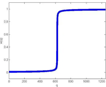
Fig. 3. Plot of w(q)for the HSMM, with the parametersk= 1, D= 1, a= 0.5andw0= 0.01.
Fig. 4. Plot ofM(q)for the HSMM, with the parametersk= 1, D= 1, a= 0.5, w0= 0.01, Ron= 1ΩandRof f = 125Ω. [3]
Proceedings of the World Congress on Engineering and Computer Science 2014 Vol I WCECS 2014, 22-24 October, 2014, San Francisco, USA
ISBN: 978-988-19252-0-6
ISSN: 2078-0958 (Print); ISSN: 2078-0966 (Online)
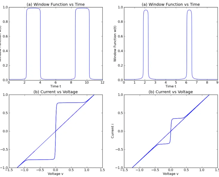
Fig. 5. Simulation results of the HSMM with our window function when the input is the current sourcei(t) =sin(t). The values of parameters are the same as Fig.4. (a) the dynamics of the window function and (b) itsi−v
response
IV. SIMULATION AND DISCUSSION
In this section, we do some simulations based on HSMM with various driving sources to test the different perfor-mances in Matlab and Python, then some advantages of our new memristor model are discussed at the rest of this section. The simulation results of the HSMM are shown in Fig. 3, 4, 5, 6 and 7,which show that this model has matched the HP numerical model and satisfied all of memristors’ observed features. According to HP [3], the memristor has two stable states, which are the ‘on’ state and the ‘of f’ state with low resistance and high resistance, respectively. Apparently, two stable states could be observed in Fig. 3 and Fig. 4 by using the HSMM. Fig. 5 and Fig. 6 offer the plots of the i/v pinched hysteresis loop characteristic, as Chua announced that ‘If it’s pinched, it’s a memristor’, which is a terse and typical memristor characterization [23]. In the experiment, when the frequency of the input current
Fig. 6. Simulation results of the HSMM with our window function when the input is the current sourcei(t) =sin(1.5t). The values of parameters are the same as Fig.4. (a) the dynamics of the window function and (b) its i−vresponse
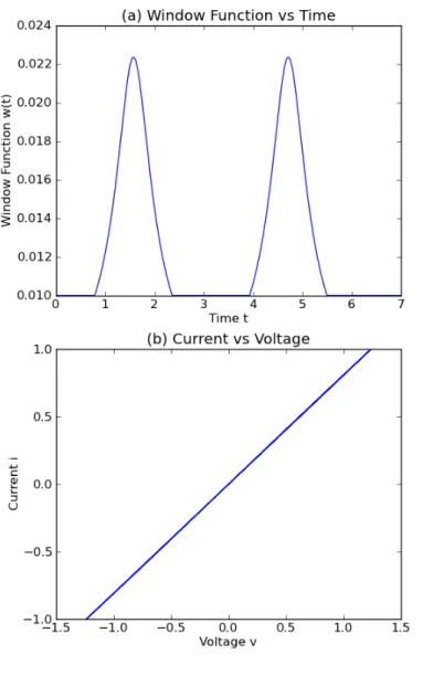
source raises 1.5 times larger, it shows that the ‘pinched hysteresis loop’ shrinks with the increase in the input fre-quency in Fig. 5(b) and Fig. 6(b). In point of fact, when the input frequency increases continuously towards infinity, the pinched hysteresis loop could shrink and become a linear function (Fig. 7(b)). As a special case, the behaviour of a memristor is more or less like a linear resistor.
One of the benefits of the new memristor model is the flexibility, because it could be used to model various memristors by setting the variable parameter ‘a’ in the window function (4). The most significant advantage and unique point of HSMM is that this model can provide either an asymmetric or symmetric window function by varying parameter ‘a’ (see Fig. 2), unlike some existing memristor models, which are with symmetric window functions, such as [3], [18], [21]. There is no evidence to show that a memristor changes from one state to another state in a symmetric way. Another strong point of this model is that the function Proceedings of the World Congress on Engineering and Computer Science 2014 Vol I
WCECS 2014, 22-24 October, 2014, San Francisco, USA
ISBN: 978-988-19252-0-6
ISSN: 2078-0958 (Print); ISSN: 2078-0966 (Online)
Fig. 7. Simulation results of the HSMM with our window function when the input is the current source i(t) =sin(2t). The values of parameters are the same as Fig.4. (a) the dynamics of the window function and (b) its i−vresponse
of the memristance M(q) could be calculated through (6) and (7), and a numerical value of the memristance M(q)
would be easily computed from those functions. This offers a convenient way to analyse and investigate memristors or applications based on memristors.
V. CONCLUSION
The Hard Switching Memristor model, made up on the basis of the HP memristor state equations and the equations modelling the boundary effects, offers critical characteristics of the memristor and provides a new asymmetric feature which has not been investigated in existing models. The shape of the HSMM window function could be flexibly set up to model different kinds of memristors by controlling the parameter ‘a’. With the HSMM, we can not only model a single memristor but also a memristive system based on memristors.
During past years, the scientific community is witnessing an enormous development of new computing technologies and more specifically in the field of nanotechnology. With the development of nano-level memristors and the discovery of more memristor physical material, memristor models would become more significant in circuits and systems.
REFERENCES
[1] L. Chua, “Memristor-the missing circuit element,” Circuit Theory, IEEE Transactions on, vol. 18, no. 5, pp. 507–519, 1971.
[2] L. O. Chua, C. A. Desoer, and E. S. Kuh,Linear and nonlinear circuits. McGraw-Hill New York, 1987.
[3] D. B. Strukov, G. S. Snider, D. R. Stewart, and R. S. Williams, “The missing memristor found,” Nature, vol. 453, no. 7191, pp. 80–83, 2008.
[4] R. Williams, “How we found the missing memristor,”Spectrum, IEEE, vol. 45, no. 12, pp. 28–35, 2008.
[5] J. J. Yang, D. B. Strukov, and D. R. Stewart, “Memristive devices for computing,”Nature nanotechnology, vol. 8, no. 1, pp. 13–24, 2013. [6] F. Z. Wang, N. Helian, S. Wu, M.-G. Lim, Y. Guo, and M. A. Parker,
“Delayed switching in memristors and memristive systems,”Electron Device Letters, IEEE, vol. 31, no. 7, pp. 755–757, 2010.
[7] K. Eshraghian, K.-R. Cho, O. Kavehei, S.-K. Kang, D. Abbott, and S.-M. S. Kang, “Memristor mos content addressable memory (mcam): Hybrid architecture for future high performance search engines,”Very Large Scale Integration (VLSI) Systems, IEEE Transactions on, vol. 19, no. 8, pp. 1407–1417, 2011.
[8] F. Z. Wang, N. Helian, S. Wu, X. Yang, Y. Guo, G. Lim, and M. M. Rashid, “Delayed switching applied to memristor neural networks,”
Journal of Applied Physics, vol. 111, no. 7, pp. 07E317–07E317, 2012. [9] X. Yang, W. Chen, and F. Z. Wang, “A memristor-cam (content ad-dressable memory) cell: New design and evaluation.” inInternational Conference on Computer Science and Information Technology, 2013, pp. 1045–1048.
[10] W. Chen, X. Yang, and F. Z. Wang, “Delayed switching applied to memristor content addressable memory cell,” inProceedings of the World Congress on Engineering, vol. 1, 2013.
[11] X. Yang, W. Chen, and F. Z. Wang, “A supervised spiking time dependant plasticity network based on memristors,” inComputational Intelligence and Informatics (CINTI), 2013 IEEE 14th International Symposium on. IEEE, 2013, pp. 447–451.
[12] C. Mellor, “Hp 100tb memristor drives by 2018 if you’re lucky, admits tech titan,”theregister, 2013.
[13] L. O. Chua and S. M. Kang, “Memristive devices and systems,”
Proceedings of the IEEE, vol. 64, no. 2, pp. 209–223, 1976. [14] Z. Biolek, D. Biolek, and V. Biolkov´a, “Spice model of memristor
with nonlinear dopant drift.”Radioengineering, vol. 18, no. 2, 2009. [15] M. Mahvash and A. C. Parker, “A memristor spice model for designing
memristor circuits,” in Circuits and Systems (MWSCAS), 2010 53rd IEEE International Midwest Symposium on. IEEE, 2010, pp. 989– 992.
[16] A. Radwan, M. A. Zidan, and K. Salama, “On the mathematical mod-eling of memristors,” inMicroelectronics (ICM), 2010 International Conference on. IEEE, 2010, pp. 284–287.
[17] S. Shin, K. Kim, and S. Kang, “Compact models for memristors based on charge-flux constitutive relationships,”Computer-Aided Design of Integrated Circuits and Systems, IEEE Transactions on, vol. 29, no. 4, pp. 590–598, 2010.
[18] T. Prodromakis, B. P. Peh, C. Papavassiliou, and C. Toumazou, “A versatile memristor model with nonlinear dopant kinetics,” Electron Devices, IEEE Transactions on, vol. 58, no. 9, pp. 3099–3105, 2011. [19] F. Corinto and A. Ascoli, “A boundary condition-based approach to the modeling of memristor nanostructures,” Circuits and Systems I: Regular Papers, IEEE Transactions on, vol. 59, no. 11, pp. 2713– 2726, 2012.
[20] S. Kvatinsky, E. G. Friedman, A. Kolodny, and U. C. Weiser, “Team: Threshold adaptive memristor model,”Circuits and Systems I: Regular Papers, IEEE Transactions on, vol. 60, no. 1, pp. 211–221, 2013. [21] Y. Juntang, M. Xiaomu, X. Xiangming, and W. Shuning, “A memristor
model with piecewise window function.”Radioengineering, vol. 22, no. 4, 2013.
[22] X. Mu, J. Yu, and S. Wang, “Modeling the memristor with piece-wise linear function,”International Journal of Numerical Modelling: Electronic Networks, Devices and Fields, 2014.
[23] L. Chua, “Resistance switching memories are memristors,”Applied Physics A, vol. 102, no. 4, pp. 765–783, 2011.
Proceedings of the World Congress on Engineering and Computer Science 2014 Vol I WCECS 2014, 22-24 October, 2014, San Francisco, USA
ISBN: 978-988-19252-0-6
ISSN: 2078-0958 (Print); ISSN: 2078-0966 (Online)