Adv. Radio Sci., 9, 95–98, 2011 www.adv-radio-sci.net/9/95/2011/ doi:10.5194/ars-9-95-2011
© Author(s) 2011. CC Attribution 3.0 License.
Advances in
Radio Science
Combined lumped element network and transmission line synthesis
for passive microwave structures
J. A. Russer1, F. Mukhtar1, A. Baev2, Y. Kuznetsov2, and P. Russer1
1Lehrstuhl für Nanoelektronik, Technische Universität München, Arcisstrasse 21, Munich, Germany
2Theoretical Radio Engineering Dept., Moscow Aviation Inst.,Volokolamskoe shosse, 4, GSP-3, Moscow, 125993, Russia
Abstract.Compact circuit models of electromagnetic struc-tures are a valuable tool for embedding distributed circuits into complex circuits and systems. However, electromag-netic structures with large internal propagation delay are de-scribed by impedance functions with a large number of fre-quency poles in a given frefre-quency interval and therefore yielding equivalent circuit models with a high number of lumped circuit elements. The number of circuit elements can be reduced considerably if in addition to capacitors, induc-tors, resistors and ideal transformers also delay lines are in-cluded. In this contribution a systematic procedure for the generation of combined lumped element/delay line equiv-alent circuit models on the basis of numerical data is de-scribed. The numerical data are obtained by numerical full-wave modeling of the electromagnetic structure. The sim-ulation results are decomposed into two parts representing a lumped elements model and a delay line model. The ex-traction of the model parameters is performed by application of the system identification procedure to the scattering trans-fer function. Examples for the modeling of electromagnetic structures are presented.
1 Introduction
The importance for applying circuit-theoretic multi-port con-cepts in the modeling of wireless communication links al-ready has been pointed out in Ivrlac and Nossek (2010). Dif-ferent from simple information theoretic models multi-port models allow to consider the energy flow and the coupling of antenna elements. The use two-port models of antennas already has been discussed in literature (Rogers et al., 2003; Boryssenko and Schaubert, 2007; Aberle, 2008). These mod-els yielded an improved description of antennas, however,
Correspondence to:J. A. Russer ([email protected])
due to the limited number of lumped elements the antenna could be modeled in a narrow frequency band only.
Distributed circuits can be modeled also in a broad fre-quency band with arbitrary accuracy using lumped element network models. A general way to establish network models is based on modal analysis and similar techniques (Russer, 2006; Felsen et al., 2009; Russer et al., 2010). In Russer et al. (2010) also the modeling of lossy structures on the basis of Brune’s equivalent circuit realization has been dis-cussed. However, electromagnetic structures with large inter-nal propagation delay are described by impedance functions with a large number of frequency poles in a given frequency interval and therefore yielding equivalent circuit models with a high number of lumped circuit elements. The number of circuit elements can be reduced considerably if in addition to capacitors, inductors, resistors and ideal transformers also delay lines are included. A combined lumped elements and delay line approach already has been presented in Shevgunov et al. (2008).
In this contribution a systematic procedure for the gener-ation of a combined lumped element/delay line equivalent circuit model for a wireless transmission link on the basis of numerical data is described. The numerical data are ob-tained by numerical full-wave modeling of the electromag-netic structure. The simulation results are decomposed into two parts representing a lumped elements model and a delay line model. The extraction of the model parameters is per-formed by application of the system identification procedure to the scattering transfer function. Examples for the model-ing of electromagnetic structures are presented.
2 Model of a wireless link
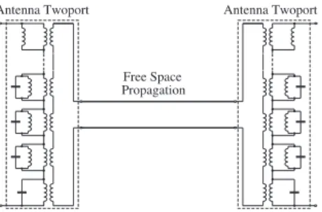
Let us consider the easiest case of a wireless transmission link consisting of two antennas connected in the far-field over free-space. Figure 1 shows this arrangement schematically. InZrepresentation the voltage-current relations are given by
96 J. A. Russer et al.: Lumped element network and TL synthesis for passive microwave structures
1 2
V1 V2
I1 I2
Fig. 1.Wireless transmission link with two antennas.
V1 V2
I1 I2
V10
ZG
ZL
Z
Fig. 2. Two-port representation of the wireless transmission link with source and load.
V1
V2
=
Z11Z12
Z21Z22
I1
I2
. (1)
Figure 2 shows the block diagram of the wireless link for the case where antenna 1 is the transmitting antenna and an-tenna 2 is the receiving anan-tenna. The transmitter has the open source voltageV10 and the source impedance ZG. The re-ceiving antenna is terminated with the load impedanceZL. Under these conditions the input and output currentsI1and
I2, respectively are given by
I1=
Z22+ZL
(Z11+ZG)(Z22+ZL)−Z12Z21
V10, (2)
I2=
Z21
(Z11+ZG)(Z22+ZL)−Z12Z21
V10. (3)
Figure 3 shows the schematic two-port representation of the link with source and load whereZ12andZ21are represented by current controlled voltage sources. The input impedance
Zinof the wireless link two-portZterminated byZLis given by
Zin=Z11−
Z12Z21
Z22+ZL
. (4)
The available powerPaof the transmitter is given by
Pa=
|V10|2 8ℜ{ZG}
. (5)
The power delivered to the loadRLis
PL= 1
2ℜ{ZL}|I2| 2.
(6) The transducer power gain is defined as
Gt=
PL
Pa
= 4|Z21|
2ℜ{Z
G}ℜ{ZL}
|(Z11+ZG)(Z22+ZL)−Z12Z21|2
. (7)
In a wireless transmission link the reaction of the receiving antenna on the transmitting antenna usually is negligible, i.e.
|(Z11+ZG)Z22| ≫ |Z12Z21|. In this case we can approxi-mate the transducer power gain by the unilateral power gain.
V1 V2
I1 I2
V10 ZG
ZL Z11 Z22
Z12I2 Z21I1
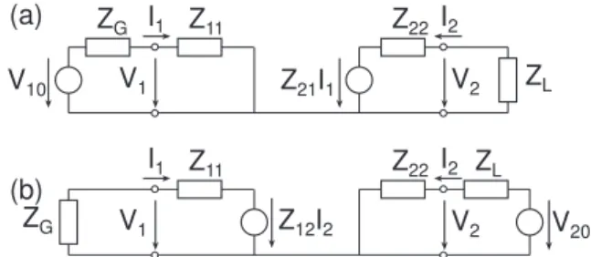
Fig. 3. Two-port representation of the wireless transmission link with source and load whereZ12andZ21are represented by current
controlled voltage sources.
V1 V2
I1 I2
V20 ZL
ZG
Z11 Z22
Z12I2
V1 V2
I1 I2
V10 ZG
ZL Z11 Z22
Z21I1 (a)
(b)
Fig. 4.Two-port representation of the unilateralized wireless trans-mission link with source and load(a)with antenna 1 as the trans-mitting antenna,(b)with antenna 2 as the transmitting antenna.
Depending on the direction of transmission we can replace the reciprocal wireless link models by the non-reciprocal models shown in Fig. 4. In this case the power gainGt is approximated by the unilateral power gain
Gtu=
4|Z21|2ℜ{ZG}ℜ{ZL}
|(Z11+ZG)(Z22+ZL)|2
. (8)
We note that in this approximation the antenna feed impe-dances of antenna 1 and antenna 2 are given byZ11andZ22 respectively.
The unilateral power gain exhibits its maximum value
Gtu,max for power matching at the input and output, i.e.
ZG=Z11∗,ZL=Z∗22and is given by
Gtu,max=
|Z21|2 4ℜ{Z11}ℜ{Z22}
. (9)
3 The two-port antenna model
As long as the coupling of the antenna with the other antenna is neglected the antenna can be considered as a passive one-port. If the antenna is coupled with one or more other anten-nas over the far-field only, the driving point impedanceZin of this antenna one-port will not be influenced by the other antennas. In the following we assume the antenna itself to be lossless. The real part of the antenna driving point impedance in that case is only due to the active power radiated by the antenna. Zin is a positive real impedance function. A one-port with a positive real impedance function can be repre-sented by a reactive reciprocal two-portZRterminated by a real resistorRr(Guillemin, 1957). Figure 5 shows the block
J. A. Russer et al.: Lumped element network and TL synthesis for passive microwave structures 97
V1
I1
Rr
Zin
REACTIVE TWO−PORT
MODEL
Fig. 5.Two-port antenna model.
n :12 3
n :1M
Linf
L2
L3
C3
C2
n :1
C1 L1n :11
C0 n :10
Fig. 6.Foster realization of the reactive two-port.
diagram of the two-port antenna model. The determination of the positive rational impedance functions of the two-port was performed by system identification methods (Kuznetsov et al., 2004; Russer et al., 2010).
An approximation of the lossless reciprocal two-port ba-sed on a finite number of poles of its two-port reactance ma-trixZR can be realized with a finite number of capacitors, inductors and ideal transformers. Figure 6 shows the canoni-cal Foster realization of the reactive two-port (Russer, 2006; Felsen et al., 2009; Russer et al., 2010).
The complete impedance matrix describing a circuit with a finite number of poles is obtained by parallel connecting the circuits describing the individual poles. In the canonical Foster representation, the impedance matrixZ(ω)is given by
Zλ(ω)= 1
j ωC0 B0+
N
X
λ=1 1
j ωCλ
ω2
ω2−ω2
λ
Bλ+j ωL∞B∞.
(10) The frequency independent rank 1 matricesBλare given by Bλ=
n2λnλ
nλ 1
, (11)
where thenλare the turns ratios of the transformers.
We have applied the methods described in this paper to model communication links between monolithic integrated on-chip antennas. Figure 7 shows a photograph of an open-chip antenna with CMOS circuits under the antenna elec-trode (Yordanov and Russer, 2010). The antennas have been measured on-wafer and diced.
Fig. 7.Photograph of the open slot antenna (Yordanov and Russer, 2010).
Fig. 8.|Z11|of the wireless transmission link.
Figure 8 shows the comparison of the|Z11|data obtained from numerical simulation with the data computed from the two-port model according to Fig. 5 with the reactive Foster two-port model shown in Fig. 6. The numerical full-wave simulations have been performed using CST software. Based on four pairs of poles and two single poles at zero and infinity the two-port model provides an accurate model of Z11 for the frequency band from 65 GHz to 69 GHz. The frequency range may be extended by increasing the number of poles.
4 The wireless link model
To extend the two-port antenna model to the full wireless link model we start from the assumption that the losses in the antenna are mainly radiation losses. In this case we can assume that the reactive two-port in Fig. 6 models the near-field of the antenna whereas the real resistorRrmodels the energy dissipation in the far-field. Considering dispersion-free single-path propagation between the two antennas, we can model the free-space propagation of the electromagnetic wave by a dispersion-free lossy transmission line (TL). The length of this transmission line corresponds to the distance between the antennas and the attenuation follows from Friis transmission formula (Russer, 2006).
This yields the model of the complete wireless transmis-sion link shown in Fig. 9. The scattering matrix of the lossy
98 J. A. Russer et al.: Lumped element network and TL synthesis for passive microwave structures
Fig. 9.Model of the complete wireless transmission link.
Fig. 10.|Z12|of the wireless transmission link.
transmission line with wave impedanceRris given by
SL=aexp(−j kr) kr
0 1 1 0
, (12)
wherearepresents the attenuation according to the Friis for-mula andr is the distance between the antennas. The corre-spondingZ-matrix is given by
ZL=Z0
1+a2 exp(−2j kr)
(kr)2 1−a2 exp(−2j kr)
(kr)2
aexp(−j kr) kr 1−a2 exp(−2j kr)
(kr)2 aexp(−j kr)
kr 1−a2 exp(−2j kr)
(kr)2
1+a2 exp(−2j kr)
(kr)2 1−a2 exp(−2j kr)
(kr)2
. (13)
Foraexp(kr−j kr)≪1 this can be approximated by
ZL≈Z0 "
1 aexp(kr−j kr)
aexp(−j kr)
kr 1
#
. (14)
Figure 10 shows the comparison of the numerical data of
|Z12| obtained from the full-wave simulation of the wire-less transmission link with the data computed from the model shown in Fig. 9. The stronger deviation between these data, compared with the case of|Z11|may be due to losses in the antenna and will be subject to further investigations.
5 Conclusions
We have presented an accurate method for generation of compact circuit models of wireless transmission links, where the antenna structure and the near-field regions are modeled by reactive lumped element networks and the far-field prop-agation by dispersion-free lossy transmission lines. Further investigations will extend this work towards multi-antenna systems and multi-path propagation. This should provide a framework for physical modeling of MIMO systems.
Acknowledgements. This work was supported by the Deutsche Forschungsgemeinschaft.
References
Aberle, J.: Two-Port Representation of an Antenna With Applica-tion to Non-Foster Matching Networks, Antennas and Propaga-tion, IEEE Transactions on, 56, 1218–1222, 2008.
Boryssenko, A. O. and Schaubert, D. H.: On optimal port loading conditions for maximizing product of energy gain and bandwidth in broadband antenna links, IEEE Transactions on Antennas and Propagation, 55, 3668–3676, 2007.
Felsen, L. B., Mongiardo, M., and Russer, P.: Electromagnetic Field Computation by Network Methods, Springer, Berlin, Germany, 2009.
Guillemin, E. A.: Synthesis of Passive Networks, Wiley, New York, 1957.
Ivrlac, M. T. and Nossek, J. A.: Toward a Circuit Theory of Com-munication, Circuits and Systems I: Regular Papers, IEEE Trans-actions on, 57, 1663–1683, 2010.
Kuznetsov, Y., Baev, A., Coccetti, F., and Russer, P.: The Ultra Wideband Transfer Function Representation of Complex Three-Dimensional Electromagnetic Structures, in: 2004 International Symposium on Signals, Systems, and Electronics ISSSE’04, Au-gust 10-13, Linz, Austria, 2004.
Rogers, S. D., Aberle, J. T., and Auckland, D. T.: Two-port model of an antenna for use in characterizing wireless communications systems, obtained using efficiency measurements, IEEE Anten-nas and Propagation Magazine, 45, 115–118, 2003.
Russer, P.: Electromagnetics, Microwave Circuit and Antenna De-sign for Communications Engineering, Artech House, Boston, second edn., 2006.
Russer, J. A., Kuznetsov, Y., and Russer, P.: Discrete-time net-work and state equation methods applied to computational elec-tromagnetics, Mikrotalasna Revija (Microwave Review), pp. 2– 14, 2010.
Shevgunov, T., Baev, A., Kuznetsov, Y., and Russer, P.: Lumped element network synthesis for one-port passive microwave struc-tures, in: Microwaves, Radar and Wireless Communications, 2008. MIKON 2008. 17th International Conference on, pp. 1– 4, 2008.
Yordanov, H. and Russer, P.: Area-Efficient Integrated Antennas for Inter-Chip Communication, in: Proceedings of the 40th Euro-pean Microwave Conference, EuMC 2010, Paris, France, 2010.