DOI: 10.13164/re.2016.0693 ELECTROMAGNETICS
A Wideband Slot Antenna with Folded Parasitic Line
for Multiple Band Operation
Chatree MAHATTHANAJATUPHAT, Narintra SRISOONTORN, Thanakarn SUANGUN,
Prayoot AKKARAEKTHALIN
Dept. of Electrical and Computer Engineering, King Mongkut’s University of Technology North Bangkok, 1518 Pracharat 1 Rd., Wongsawang, Bangsue, Bangkok, Thailand 10800
cmp@kmutnb.ac.th, ple1975@hotmail.com, s.thanakarn@gmail.com, prayoot@kmutnb.ac.th
Manuscript received March 17, 2016
Abstract. The rectangular slot antenna with rectangular stub for a wide impedance bandwidth is proposed. In addi-tion, the interference frequency band has been rejected by placing the folded parasitic line surrounding the rectan-gular stub of the presented antenna. The bidirectional radiation patterns are obtained at all operating frequen-cies. Also, the average gain of the presented antenna is approximately 3 dBi. The antenna properties such as re-flection coefficient, radiation patterns and gains are evalu-ated via numerical simulation and measurement. The pre-sented antenna can support the multiple band operation at frequency bands of 824–960 MHz and 1710–2485 MHz.
Keywords
Wideband, slot antenna, parasitic line, notched frequency
1.
Introduction
Nowadays, wireless communication systems, which use antennas to radiate or receive electromagnetic waves, have been grown very fast wherever in mobile communi-cations, warehouse manufacturing systems, industrial communications, medical services, and etc. [1–4]. Also, many wireless communication systems require antennas responding to multiband operation with low profile. How-ever, multiband antennas could be designed by using either multi-resonators or wideband notch technique to produce multiple band operation [5–8].
In literature review, the antenna with multiple reso-nators was proposed consisting of a two-strip monopole and a meandered strip line for responding to low and high resonant frequencies, respectively [9]. Next, the antenna using parasitic element was designed to perform three resonant modes [10]. This antenna includes the L-shape stub acting as the transmission line, and a U-shape stub for responding to the first and second resonance frequencies. Also, the third resonant frequency of the antenna was
occurred due to the slot of the U-shape stub. Especially, the multiband antenna composing of the monopole strip line connecting to the bow-tie patch to radiate at the first and third resonant frequencies, respectively, and the parasitic loop placed on the bottom layer responding to the second resonant frequency was presented in [11]. As the previous reviews, the multiband antennas designed by using multi-ple resonator technique can radiate independently electro-magnetic field at each resonant frequency. However, it is very difficult for designing this type of antenna because the electromagnetic coupling between resonators affects to the impedance bandwidth.
in [16]. It has been found that the notched frequency band can be varied by adjusting the open-circuit stub. However, both presented antennas in [15], [16] have very narrow band notches and it is very difficult to create the band notches at low frequency due to limited spaces for parasitic elements. Therefore, this technique may not be suitable to use for multiple band operation in some modern wireless communication systems. To overcome this problem, a new folded step parasitic line is proposed to be used with a con-ventional wideband slot antenna in this paper. By using this technique, not only the notched band at lower frequen-cy can be obtained but also the impedance bandwidth can be easily adjusted.
The proposed antenna consists of a rectangular slot with a rectangular stub to generate the wideband operation. Coupled electromagnetic fields between the antenna and the folded step parasitic line will create a notched fre-quency. Furthermore, the notched frequency band can be independently adjusted even at the low frequency due to there is no area limitation of antenna slot. Especially, the proposed antenna can cover the operating frequency bands of GSM 850 (Global System for Mobile communication) (824–894 MHz), GSM 900 (890–960 MHz), DCS 1800 (Digital Communication System) (1710–1880 MHz), PCS 1900 (Personal Communication System) (1850 to 1990 MHz), UMTS 2100 (Universal Mobile Telecommu-nication System) (1920–2170 MHz), and WLAN IEEE802.11b/g (Wireless Local Area Network) (2400 to 2484 MHz). The significant parameters of the proposed antenna will be investigated by using the CST microwave studio software. The presented antenna prototype will be determined and experimented.
The organization of the paper consists of antenna de-sign in Sec 2. Then, parameter study will be performed in Sec. 3. Also, simulation and experiment of antenna char-acteristics will be verified in Sec. 4. Finally, results and conclusions of the presented antenna are given in Sec. 5.
2.
Antenna Design
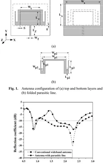
Figure 1(a) illustrates the configuration of the pre-sented antenna with folded parasitic line. It composes of a rectangular slot and a rectangular patch stub to perform wideband operation. In addition, the folded parasitic line, as depicted in Fig. 1(b), is placed on the surrounding of the rectangular patch stub to create a notched band for pre-venting unwanted frequency. Also, the rectangular patch stub is excited by connecting with the 50 Ω microstrip line (Wf = 3 mm) fed by the SMA connector. The presented
antenna is designed on the substrate of FR-4 with the thickness h of 1.6 mm and the relative permittivity εr of
4.1.
Therefore, the rectangular patch stub is evaluated and optimized to cover the high frequency of the wideband an-tenna, which has the dimension (Lt Wt) of 30.5 47 mm2.
Moreover, the rectangular slot with the dimension of
(a)
(b)
Fig. 1. Antenna configuration of (a) top and bottom layers and
(b) folded parasitic line.
Fig. 2. Simulated reflection coefficients of the wideband slot
antennas with and without folded parasitic line.
(Ws Ls) 75.5 49 mm2 is determined to reinforce the low
and high frequencies of the wideband antenna. As the re-sults, the conventional wideband slot antenna can be cre-ated. Consequently, the convention wideband slot antenna will be combined with the folded parasitic line to create the undesired frequency rejection band as the result depicted in Fig. 2. It can be clearly seen that the wideband antenna with the folded parasitic line has lower reflection coeffi-cient level than the wideband antenna without it at the resonant frequency of 1.44 GHz, as a notched frequency. The simulated notch bandwitdth is about 700 MHz (from 977 MHz to 1.7 GHz) caused by the step impedance of the folded parasitic line. Due to its low impedance, the folded parasitic line absorbs a large amount of current distribution to create a wideband notch at the resonant frequency of 1.44 GHz. However, it is not either disturbed or slightly disturbed total radiation impedance of the antenna at ranges of 824–960 MHz and 1710–2485 MHz.
In order to investigate antenna parameter affecting to the notched frequency and impedance bandwidth, the significant parameters of LP3, Ws, and g of the presented
3.
Parametric Study
This section presents the investigation of significant parameters to comprehend behaviors of the proposed an-tenna and evaluate the optimum values. Before investigat-ing the significant parameters of LP3, Ws, and g to
under-stand and observe the antenna behavior such as a notched frequency, resonant frequency, and impedance bandwidth, the optimum parameters of the presented antenna have been fixed as following: Wp1 = 57.5 mm, Wp2 = 69.5 mm,
Wp3 = 1 mm, Wt = 47 mm, Wf = 3 mm, W = 84.5 mm,
Lp1 = 3 mm, Lp2 = 7 mm, Lt = 30.5 mm, Lf = 21.5 mm,
Ls = 49 mm, L = 92 mm, S = 0.5 mm.
In order to investigate the notched frequency re-sponse, the significant parameters of Ws = 75.5 mm,
g = 1.5 mm should be initiated. Also, the parameter LP3 has
been altered to 27 mm, 31 mm, and 35 mm, respectively, to observe the effect of notched frequency, as results illus-trated in Fig. 3. When increasing the value of parameter LP3
as depicted in Fig. 3, it has been clearly found that the notched frequency shifts to the lower frequency because the electrical length of the folded parasitic line is extended. Moreover, the lower cut off frequency of the second band shifts to the lower frequency and impedance bandwidth widens because the extending of the parameter LP3 is close
to the upper ground side of the bottom layer, resulting in the electromagnetic coupling effect between them. How-ever, the parameter LP3 = 31 mm should be selected to
avoid the interference frequency and remain for supporting sufficient operating frequency band of 1710 to 2485 MHz.
Additionally, the resonant frequency will be investi-gated by varying the parameter Ws. In Fig. 4, it could be
obviously seen that the first resonant frequency shifts to the lower frequency, as increasing the parameter Ws =
71.5 mm, 75.5 mm, and 79.5 mm while the parameters of LP3 = 31 and g = 1.5 mm are fixed, due to the increasing
electrical length of the inner slot of the presented antenna, resulting in the narrow impedance bandwidth in the second resonant frequency band. Especially, the optimum value of parameter Ws = 75.5 mm has been chosen to create the pre
sented antenna covering the operating frequency bands of 824–960 MHz and 1710–2485 MHz. Furthermore, as the parameters of LP3 = 31 mm and Ws = 75.5 mm fixed, the
impedance bandwidth of the presented antenna could be observed by varying the parameter of g = 0 mm, 1.5 mm, and 3 mm, respectively. As the results illustrated in Fig. 5, it has been noticed that the upper frequency of the first frequency band shifts to the higher frequency and the im-pedance bandwidth is improved as increasing the parame-ter g = 0 mm, 1.5 mm, and 3 mm, respectively because of the matching impedance of the antenna closed to 50 ohm at the operating frequency band. However, the parameter g =1.5 mm is suitable to obtain the desired operating fre-quency bands of 824–960 MHz and 1710–2485 MHz. Therefore, the optimum parameter values of LP3 = 31 mm,
Ws = 75.5 mm, and g = 1.5 mm are obtained and used to
fabricate the presented antenna.
Fig. 3. Simulated reflection coefficients of the presented
antenna as varied Lp3 = 27 mm, 31 mm, and 35 mm.
Fig. 4. Simulated reflection coefficients of the presented
an-tenna as varied Ws = 71.5 mm, 75.5 mm, and 79.5 mm.
Fig. 5. Simulated reflection coefficients of the presented
antenna as varied g = 0 mm, 1.5 mm, and 3 mm.
4.
Results and Discussion
covering the operating frequency bands of 824–960 MHz and 1710–2485 MHz.
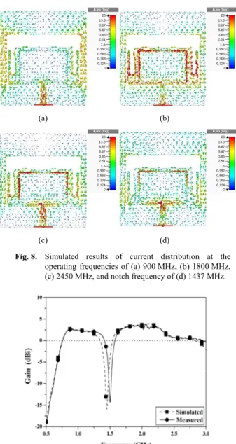
Additionally, the simulated current distribution will be investigated to verify the antenna mechanism as shown in Fig. 8. At the frequency of 900 MHz, the major current distribution flows through the outer edge of the slot on metallic ground at the antenna bottom layer, which has the electrical length about 10,as depicted in Fig. 8(a). It has
been noticed that the outer edge of slot responses to the first frequency band of 824–960 MHz. As the results shown in Fig. 8(b), it can be clearly seen that the main cur-rent distribution is occurred on the rectangular stub edge to propagate the electromagnetic filed at inner slot, which it has the electrical length about 10at the operating
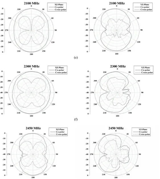
fre-quency of 1800 MHz. Moreover, the simulated current distribution is evaluated at the operating frequency of 2450 MHz as illustrated in Fig. 8(c). It has been found that the current distribution flows on the upper edge region of the rectangular stub. This results in tilting the electromag-netic field radiation of the main beam at the angle of 330 degree and 210 degree in YZ-plane at the operating frequency of 2450 MHz. Especially, the notched frequency of the antenna can be verified by current distribution on the folded parasitic line as shown in Fig. 8(d). As the result, it has been noticed that the major current distribution flows on the folded parasitic line at the notched frequency of 1437 MHz. The folded parasitic line performs as a load to absorb the electromagnetic field, which the result can be considered with the antenna gain as illustrated in Fig. 9. However, in the measured result, the lowest gain is slightly shifted from 1437 MHz to the higher frequency due to a little antenna fabrication error. It has been indicated that the antenna gain responds to the operating frequency bands of 824–960 MHz and 1710–2485 MHz and the gain is eliminated at the notched frequency of 1437 MHz con-sistent with the current distribution flowing in Fig. 8(d). However, the antenna average gain is approximately 3 dBi at the angle of 0 degree at the operating frequencies. The measured radiation patterns of the presented antenna at all operating frequencies are depicted in Fig. 10. It has been clearly found that the cross polarization patterns expand when the frequency is higher than 1800 MHz. This is due to the current distribution flowing through the rectangular
Fig. 6. Prototype of the fabricated slot antenna with folded
parasitic line.
Fig. 7. Simulated and measured reflection coefficients of the
presented antenna.
(a) (b)
(c) (d)
Fig. 8. Simulated results of current distribution at the
operating frequencies of (a) 900 MHz, (b) 1800 MHz, (c) 2450 MHz, and notch frequency of (d) 1437 MHz.
Fig. 9. Simulated and measured total gains of the presented
antenna.
5.
Conclusion
The wideband rectangular slot antenna with rectgular stub and folded parasitic line is presented. The an-tenna creates a frequency rejection band for eliminating the interference frequency resulting from the folded parasitic line. The proposed antenna can operate at the frequency
bands of 824–960 MHz and 1710–2485 MHz. Further-more, the radiation patterns of the presented antenna are still bidirectional at the operating frequencies supporting applications of GSM 850, GSM 900, DCS 1800, PCS 1900, UMTS, and WLAN IEEE802.11b/g systems. The proposed antenna can be applied for mobile repeaters in subway tunnels or corridors.
(a)
(b)
(c)
(e)
(f)
(g)
Fig. 10. Measured radiation patterns of the presented antenna at the frequencies of (a) 850 MHz, (b) 900 MHz, (c) 1800 MHz, (d) 1900 MHz,
(e) 2100 MHz, (f) 2300 MHz, and (g) 2450 MHz.
Acknowledgments
This research has been supported by the cooperation of the Thailand Research Fund (TRF) under the grant number RTA-5780010 and King Mongkut’s University of Technology North Bangkok.
References
[1] ZHANG, Z., LI, M. Wireless communication management model of workshop and warehouse manufacturing system. In Proceedings
of the 2nd International Conference on Intelligent Computation
Technology and Automation ICICTA 2009. Changsha (China),
2009, vol. 4, p. 121–123. DOI: 10.1109/ICICTA.2009.74
[2] WU, K., WU, X. A wireless mobile monitoring system for home healthcare and community medical services. In The 1st
International Conference on Bioinformatics and Biomedical
Engineering (iCBBE 2007). China, July 2007, p. 1190–1193. DOI:
10.1109/ICBBE.2007.307
[3] HALL, E. S., VAWDERY, D. K., KNUTSON, C. D., et al. Enabling remote access to personal electronic medical records.
IEEE Engineering in Medicine and Biology Magazine, 2003,
vol. 22, no. 3, p. 133–139. DOI: 10.1109/MEMB.2003.1213636
[4] JONSSON, M., KUNERT, K. Towards reliable wireless industrial communication with real-time guarantees. IEEE Transactions on
Industrial Informatics, 2009, vol. 5, no. 4, p. 429– 442. DOI:
10.1109/TII.2009.2031921
[5] CAO, Y. F., CHEUNG, S. W., YUK, T. I. A multiband slot antenna for GPS/WiMAX/WLAN systems. IEEE Transactions on Antennas and Propagation, 2015, vol. 63, no. 3, p. 952–958. DOI: 10.1109/TAP.2015.2389219
[6] WU, S.-J., KANG, C.-H., CHEN, K.-H., et al. A multiband quasi-Yagi type antenna. IEEE Transactions on Antennas and
Propagation, 2010, vol. 58, no. 2, p. 593–596. DOI:
10.1109/TAP.2010.2041522
Antennas and Wireless Propagation Letters, 2008, vol. 7, p. 652 to 655. DOI: 10.1109/LAWP.2008.2007813
[8] LIU, W.-C. Design of a multiband CPW-fed monopole antenna using a Particle Swarm Optimization approach. IEEE Transactions
on Antennas and Propagation, 2005, vol. 53, no. 10, p. 3273 to
3279. DOI: 10.1109/TAP.2005.856339
[9] LIN, K.-C., LIN, C.-H., LIN, Y.-C. Simple printed multiband antenna with novel parasitic-element design for multistandard mobile phone applications. IEEE Transactions on Antennas and
Propagation, 2013, vol. 61, no. 1, p. 488–491. DOI:
10.1109/TAP.2012.2220106
[10] ZHANG, T., LI, R., JIN, G., et al. A novel multiband planar antenna for GSM/UMTS/LTE/Zigbee/RFID mobile devices. IEEE Transactions on Antennas and Propagation, 2011, vol. 59, no. 11, p. 4209–4214. DOI: 10.1109/TAP.2011.2164201
[11] MAHATTHANAJATUPHAT, C., WONGSIN, N., AKKARAEK-THALIN, P. A multiband monopole antenna with modified fractal loop parasitic for DCS 1800, WLAN, WiMAX and IMT advanced systems. IEICE Transactions on Communications, 2012, vol. E95-B, no. 1, p. 27–33. DOI: 10.1587/transcom.E95.B.27
[12] LI, Y., LI, W., LIU, C., et al. Miniaturization circular wide slot ultra wideband antenna with X-band rejection filter function. In
IEEE International Workshop on Antenna Technology (iWAT).
Tucson (Arizona, USA), 2012, p. 253–256. DOI: 10.1109/IWAT.2012.6178660
[13] PANDA, J. R., KSHETRIMAYUM, R. S. A compact CPW-fed monopole antenna with a U-shaped slot for 5 GHz/6 GHz band-notched ultrawideband applications. In Workshop on Advanced
Antenna Technology, 2010 Indian Antenna Week. Puri (India),
2010, p. 1–4. DOI: 10.1109/AAT.2010.5545942
[14] CHANG, T.-N., WU, M.-C. Band-notched design for UWB antennas. IEEE Antennas and Wireless Propagation Letters, 2008, vol. 7, p. 636–640. DOI: 10.1109/LAWP.2008.2007581
[15] HUANG, C. -Y., HUANG, S. -A., YANG, C. -F. Band-notched ultra-wideband circular slot antenna with inverted C-shaped para-sitic strip. Electronics Letters, 2008, vol. 44, no. 15, p. 891–892. DOI: 10.1049/el:20081143
[16] LUI, W. J., CHENG, C. H., ZHU, H. B. Frequency notched printed slot antenna with parasitic open-circuit stub. Electronics Letters, 2005, vol. 41, no. 20, p. 1094–1095. DOI: 10.1049/el:20052544
About the Authors …
Chartree MAHATTHANAJATUPHAT received his B.Eng. degree from King Mongkut’s University of
Tech-nology North Bangkok (KMUTNB), Thailand, in 2001 and M.Eng. degree from the University of Applied Sciences, Rosenheim, Germany, in 2003. He received the Ph.D. degree from King Mongkut’s University of Technology North Bangkok (KMUTNB). His research interests are on the designing of small antennas by using fractal geometry concept and digital signal processing for communication applications.
Narintra SRISOONTORN received the M.Eng. degree in Electrical Engineering from King Mongkut's University of Technology North Bangkok (KMUTNB), Thailand, in 2013. Currently, she is studying for Ph.D. degree at King Mongkut’s University of Technology North Bangkok (KMUTNB). Her research interests are wideband and multiband antennas, base station antennas, and mobile wireless applications.
Thanakarn SUANGUN was born in Chiangmai, Thai-land. He received the B.Eng. and M.Eng. degrees in Elec-trical Engineering from King Mongkut's University of Technology North Bangkok (KMUTNB), Thailand, in 2008 and 2010, respectively. Currently, he is studying for Ph.D. degree at King Mongkut’s University of Technology North Bangkok (KMUTNB). His research interests are wideband and multiband antennas, and telecommunication applications.