In this work, the gz coeficient, used to evaluate inal second order effects in reinforced concrete structures, is studied. At the start, the inluence of the structural model in determination of gz coeficient is evaluated. Next, a comparative analysis of gz and B2 coeficient, usually employed to evaluate second order effects in steel structures, is performed. In order to develop the study, several reinforced concrete buildings of medium height are analysed using ANSYS-9.0 [1] software. The results show that simpliied analysis provide more conservative values of gz. It means that, for structures analysed by simpliied models, large values of gz don’t imply, necessarily, in signiicant second order effects. Furthermore, it was checked that gz can be determinated from B2 coeficients of each storey of the structures and that, for all the analysed buildings, the average values of the B2 coeficients are similar to gz.
Keywords: reinforced concrete, structural model, gz Coeficient, B2 Coeficient.
Neste trabalho apresenta-se um estudo do coeiciente gz, empregado para indicar a necessidade ou não de se considerar os efeitos de segunda ordem globais na análise das estruturas de concreto armado. Inicialmente, procura-se avaliar a inluência do modelo estrutural adotado no cálculo de gz. Em seguida, realiza-se uma análise comparativa do coeiciente gz e do coeiciente B2, comumente empregado para avaliar os efeitos de segunda ordem em estruturas de aço. Para conduzir o estudo, diversos edifícios de médio porte de concreto armado são processados utilizando o programa computacional ANSYS-9.0 [1]. Os resultados obtidos permitem veriicar que análises menos reinadas tendem a fornecer valores de gz mais conservadores. Isto signiica que, para estruturas analisadas por meio de modelos simpliicados, a obtenção de altos coeicientes gz não implica necessariamente em efeitos de segunda ordem signiicativos. Além disso, mostra-se que o gz pode ser calculado a partir dos coeicientes
B2 determinados para cada pavimento das estruturas, e que, para todos os edifícios analisados, os valores médios dos coeicientes B2 apresen-tam boa proximidade em relação ao gz.
Palavras-chave: concreto armado, modelo estrutural, coeiciente gz, coeiciente B2.
Considerations about the determination of
g
z
coeficient
Considerações sobre a determinação do coeiciente
g
z
D. M. OLIVEIRA a
N. A. SILVA b
C. F. BREMER c
H. INOUE d
a Universidade Federal de Minas Gerais, Escola de Engenharia, Deptº de Engenharia de Materiais e Construção, [email protected],
Av. Antônio Carlos 6627, bl. 1, sala 3315, Pampulha, 31270-901, Belo Horizonte, MG, Brasil;
b Universidade Federal de Minas Gerais, Escola de Engenharia, Deptº de Engenharia de Estruturas, [email protected], Av. Antônio Carlos 6627, bl. 1,
Pampulha, 31270-901, Belo Horizonte, MG, Brasil;
c Universidade Federal de Minas Gerais, Escola de Arquitetura, Deptº da Tecnologia da Arquitetura e do Urbanismo, [email protected],
Rua Paraíba 697, Funcionários, 30130-140, Belo Horizonte, MG, Brasil;
d Universidade Federal de São João del-Rei, Campus Alto Paraopeba, Deptº Multidisciplinar de Tecnologia, Ciências Humanas e Sociais,
[email protected], Rod. MG 443, km 7, caixa postal 131, 36420-000, Ouro Branco, MG, Brasil.
Received: 20 Jan 2012 • Accepted: 25 Sep 2012 • Available Online: 08 Feb 2013
Abstract
1. Introduction
Of late, erecting more economical, slender structures and taller, bolder buildings has become increasingly common.
The taller and more slender the building, the greater the strains present, particularly those resulting from lateral actions. In these cases the stability analysis and evaluation of second order effects start taking on fundamental importance in the structural project. Second order effects arise when the structure equilibrium consid -ering the deformed coniguration study is done. In this way, exist -ing forces interact with displacements, thereby produc-ing addition -al efforts. Second order efforts introduced by the structure joints moving horizontally, when subject to vertical and horizontal loads, are referred to as global second order effects.
It is well known that all structures are displaceable. However, hori -zontal joint displacements are small in some more stiff structures and, as a result, second order global effects have little inluence on total efforts, and so can be ignored. These structures are referred to as nonsway structures. In these cases, bars can be sized sepa -rately, with their extremities tied, where efforts obtained by the irst order analysis are applied.
On the other hand, some more lexible structures have signiicant horizontal displacements and therefore global second order effects depict an important part of inal efforts and cannot be ignored. This is the case of sway structures for which a second order analysis must be done.
According to NBR 6118:2007 [2], if global second order effects are less than 10% of the respective irst order efforts, the structure can be classiied as being nonsway structure. Otherwise (that is, when global second order effects are over 10% higher than irst order ef -fects), the structure is classiied as being sway structure. NBR 6118:2007 [2] also establishes that structures can be classi -ied using two approximate processes, the α instability parameter and the gz coeficient. However, the gz coeficient goes beyond the α parameter, since it can also be utilized to evaluate inal efforts, which include second order efforts, as long as their value does not exceed 1.3. However, it is obvious that, for second effects to be evaluated satisfactorily, the gz coeficient needs to be calcu
-lated accurately.
It is worth noting that the gz coeficient must be employed in
reinforced concrete structures. To assess second order effects on steel structures, the B2 coeficient must be utilized. As with gz, this coeficient is also able to provide an estimate of a struc -ture’s inal efforts, as long as their value does not go beyond a certain threshold.
Within this context, this paper’s primary intention is to ascertain the adopted structural model’s inluence in calculating the gz
co-eficient. Thus, the gz values for two medium height reinforced concrete buildings are determined, considering ive distinct three-dimensional models developed utilizing ANSYS-9.0 [1] software. The results obtained make it possible to identify the more ade -quate models for putting the project into practice, as well as those whose utilization could prove disadvantageous and uneconomical. Moreover, the attempt has been made to carry out a comparative study of coeficients gz and B2. To conduct the study, irst of all an
expression associating these parameters is developed. Next, the gz
and B2 values for several medium height reinforced concrete build -ings are calculated, utilizing ANSYS-9.0 [1] software.
2. Coeficient
g
zNBR 6118:2007 [2] ordains that the gz coeficient, valid for reticu
-lated structures at least four stories high, can be determined from a irst order linear analysis, by reducing the structural elements’ stiff -ness, in order to consider the physical non-linearity approximately. For each load combination, the gz value is calculated using the fol
-lowing expression:
(1)
dtot d tot z
M
M
, , 1
,
1
1
- M1,tot,d (irst order moment) being: a sum of the all the horizontal force moments (with their design values) of the considered combi -nation relative to the structure base, which can be written as:
(2)
M
1,tot,d=
(F
hid
h
i)
Fhid being the horizontal force applied to storey i (with its design value), and hi being the height of storey i.
- ΔMtot,d (increase in moments after the irst order analysis) being: a sum of the products of all the vertical forces working on the struc -ture (with their design values), in the considered combination, by the horizontal displacements of their respective application points:
(3)
ΔM
tot,d=
(P
id
u
i)
Pid being the vertical force working on storey i (with its design val -ue), and ui being the horizontal displacement of storey i.
Bearing in mind that second order effects can be ignored as long as they do not show a greater than 10% increase in the respective irst order efforts, a structure may be classiied as being nonsway structure if its gz ≤ 1.1.
NBR 6118:2007 [2] establishes that inal efforts (irst order + sec -ond order) can be evaluated from the additional 0.95gz horizontal
efforts magniication of the considered loading combination, as long as gz does not exceed 1.3. However, according to the NBR
6118:2000 [3] Revision Project, inal efforts values could be ob -tained by multiplying the irst order moments by 0.95gz, also on
the condition that gz ≤ 1.3. It is therefore understood that gz ceased
to be the irst order moment magniier coeficient and became the horizontal loads magniier coeficient.
According to Franco &Vasconcelos [4], utilizing gz as a irst order
moments magniier provides a good estimate for the second order analysis results; the method was applied successfully on tall build -ings with gz in the region of 1.2 or more. Vasconcelos [5] adds that
-According to Silva [9], if the B2 coeficient does not exceed the value of 1.1 on all storeys, the structure can be considered almost insen -sitive to horizontal movement and, in this case, global second order effects can be ignored. When the greater B2 is situated between 1.1 and 1.4, the approximate B1-B2 method can be utilized for the bending moment, with the other efforts (axial and shearing forces) being directly obtained from the irst order analysis. Lastly, when B2 > 1.40, the recommendation is that a rigorous second order elastoplastic analysis be performed. Silva [9] also adds that, in the event 1.1 < B2 ≤ 1.2, the bending moments can alternatively be based on a irst order analysis performed with the magniied hori -zontal efforts by the greater B2.
So it can be seen that, like the gz coeficient, the B2 coeficient is an “indicator” of the importance of global second order effects on a structure. In this way, in the next item, an expression capable of relating these parameters will be obtained.
4. Relation between coeficients
g
zand
B
2Figure [1] shows a structure consisting of three storeys of equal length (L). In this igure the vertical (Pid) and horizontal (Fhid) design forces working on each storey i, along with their respective hori -zontal displacement (ui) are also shown.
To calculate gz, equation (1), the values of M1,tot,dand ∆Mtot,d need to
be determined. Through equations (2) and (3), we get, respectively:
(6)
uating second order effects by multiplying irst order moments by gzis
based on the assumption that the successive elastic lines produced by vertical force action on the structure with displaced joints follow in geometric progression. Indeed, it was seen in countless cases that up to the value gz = 1.3 this assumption is valid with less than 5% error.
However, there are some particular situations where the assumption formulated in developing the method does not apply or applies with greater errors. As examples of these exceptional cases, Vasconcelos [6] quotes: when there is a sudden change in inertia between stories (in particular between the ground and irst loor), where ceiling heights from one loor to the next are very different, cases of column transition in beams, when there is torsion in the spatial frame or uneven settling in the foundations, and others.
Oliveira [7] did an evaluation of the gz coeficient’s eficiency as a irst
order efforts magniier (for bending moments, axial and shearing forces) and as a horizontal loads magniier, to obtain inal, including second order, efforts. The study was carried out for structures with maximum gz values in the region of 1.3, that is, for which, according
to NBR 6118:2007 [2], the simpliied inal efforts evaluation process employing the gz coeficient is still valid. It was found that the gz
coef-icient must be utilized as magniier of irst order moments (and not for horizontal loads) to obtain inal moments. In the case of axial force on columns and shearing force on beams, magniication by the gz coeficient was not necessary, since the irst and second order efforts values obtained in these cases were practically the same.
3. Coeficient
B
2To evaluate second order effects on steel structures, AISC/LRFD [8] adopts the approximate method of amplifying the irst order moments by magniication factors B1 and B2. So the second order bending moment, MSd, must be determined by means of the follow -ing expression:
(4)
M
Sd= B
1
M
nt+ B
2
M
ltMnt being the design bending moment, assuming there is no side sway in the structure, Mlt being the design bending moment due to the frame’s side sway; both Mnt and Mlt are obtained by irst order analyses. The B1 ampliication coeficientdepicts the P-δ effect, relating to the instability of the bar, or to local second order effects; B2 considers the P-Δ effect, relating to the instability of the frame, or to global second order effects.
The B2 coeficient can be calculated for each storey of the structure, as:
(5)
Sd Sd h
0 2
H
N
L
1
1
B
with ΣNSd as the summation of the design axial compression forces on all the columns and other elements resistant to the storey’s ver -tical forces;∆0h as the relative horizontal displacement; L as the storey’s length and ΣHSd as the summation of all the design hori
-zontal forces on the storey producing ∆0h.
Figure 1 – Three-storey structure subjected
to vertical and horizontal forces
L
L
L
3
u
2
u
1
u
P
P
P
F
h3d
h2d
F
F
h1d
3d
2d
(16)
3, 2 3 3 3 3 3 3 3, 2 3 3 3,2
M
M
B
M
M
M
M
1
B
M
M
1
1
B
Adding up M1, M2 and M3, equations (8), (11) and (14), and ∆M1, ∆M2 and ∆M3, equations (9), (12) and (15) gives:
(17)
M
1+ M
2+ M
3= F
h1d
L + 2F
h2d
L + 3F
h3d
L
(18)
M
1+
M
2+
M
3= P
1d
u
1+ P
2d
u
2+ P
3d
u
3Comparing equations (17) and (18) with equations (6) and (7) we can write:
(19)
M1,tot,d= M1 + M2 + M3
(20)
M
tot,d=
M
1+
M
2+
M
3By substituting equations (19) and (20) in equation (1), the gz
coef-icient becomes deined as:
(21)
)
(
)
(
)
(
1 1 2 2 3 33 2 1
M
M
M
M
M
M
M
M
M
z
Inverting equation (21) gives:
(22)
3 2 1 3 3 2 2 11
)
(
)
(
)
(
1
M
M
M
M
M
M
M
M
M
z
(7)
M
tot,d= P
1d u
1+ P
2d u
2+ P
3d u
3The B2 coeficient, given by equation (5), shows distinct values for each storey of the structure. Thus, referring to the B2 coeficient of storey i as B2,i and the parts (L.ΣHSd) and (∆0h.ΣNSd) as Mi and ∆Mi, respectively, we get:
n 1st storey:
(8)
(9)
(10)
1, 2 1 1 1 1 1 1 1, 2 1 1 1, 21
1
1
B
M
M
M
M
M
M
B
M
M
B
n 2nd storey:
(11)
M
2= L (F
h2d+ F
h3d) = F
h2d L + F
h3d L
(12)
(13)
2, 2 2 2 2 2 2 2 2, 2 2 2 2, 2B
M
M
M
M
M
M
1
B
M
M
1
1
B
n 3rd storey:
(14)
M
3= L
(F
h3d) = F
h3d
L
(15)
Substituting equations (10), (13), (16) and (19) in equation (22), gives:
(23)
Finally equation (23) can be written as:
(2
4)
3 , 2
3
2 , 2
2
1, 2
1
z
B
c
B
c
B
c
1
with constants c1, c2and c3 being given respectively through:
(25)
(2
6)
(2
7)
As such, for a structure consisting of n storeys, the gz coeficient can be calculated by reference to the B2 coeficient as:
(28)
and
(29)
5. Inluence of the structural model
adopted to calculate
g
zAs commented previously, NBR 6118:2007 [2] establishes that the gz coeficient can be determined from a irst order structure analysis. However, this analysis can be carried out utilizing vari -ous types of structural models. For example, a building can be modelled considering the slabs as rigid diaphragms or depicting them by means of shell elements. Additionally, the eccentricity ex -isting between the beam axis and the average slab plane may or may not be taken into account. In this way, in order to evaluate the possible inluence of the structural model on the value ofgz, the gz
coeficients will be determined for two reinforced concrete build -ings, considering ive distinct three-dimensional models developed utilizing ANSYS-9.0 [1] software. The results of these models will then be analyzed and compared.
5.1 Buildings and models analyzed
The irst building analyzed, shown in igure [2], consists of sixteen storeys (with a 2.9 m ceiling height) and is symmetrical in both X and Y directions. 20 MPa for the characteristic strength of the concrete to compression and a Poisson coeficient equal to 0.2 were adopted.
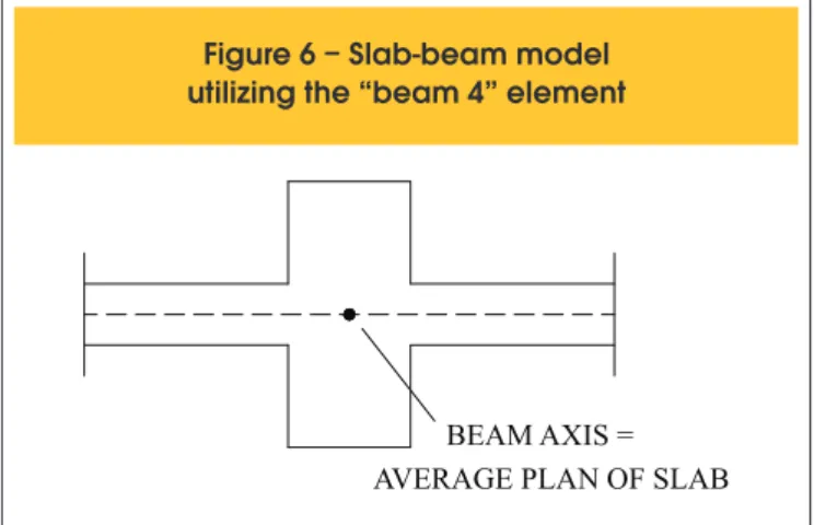
beams. In this way, in this model the average slab plane coincides with the beam axis, igure [6], since the “beam 4” element does not allow eccentricities to be considered.
In the third model, the columns and beams are depicted by means of the “beam 4” element and the slabs are treated as rigid diaphragms, that is, it is accepted that they have ininite stiffness on their own plane and nil stiffness crosswise. In the ANSYS-9.0 software [1], the hypothesis of a rigid diaphragm is embodied in the model by means of a speciic command which relates the degrees of freedom of the nodes making up the slab plane. Thus, a “master” node, corresponding to the point representing all the storey’s nodes is deined. The remaining nodes, called “slaves”, have their own degrees of freedom and those represented by the “master” node.
The fourth model, like the previous one, is also made up of bars (depicting the columns and beams by means of the “beam4” element), but without considering the hypothesis of a rigid diaphragm.
Finally, the last model only differs from the previous one because the “beam4” element is replaced by the “beam44” element to de -pict the beams, whereby the eccentricity existing between the beam axis and the average slab plane can be considered. It can be seen, then, that in models 3,4, and 5 the structural sys -tem just consists of bars, since the slabs are not modelled (unlike
models 1 and 2 in which the slabs are depicted by means of shell elements). In all the models, the beams’ torsional stiffness was reduced, by reproducing the cracking effect.
Table [1] sums up the main characteristics of the models employed.
5.2 Design considerations
The actions working on the buildings are divided into two groups: vertical actions and horizontal actions.
Vertical actions consist of permanent loads and the accidental load. The permanent loads considered were the own weights of structures, the masonry loads and the slab coatings and inishings. The accidental loads were determined in accordance with the pre -cepts of NBR 6120:1980 [12].
The chief horizontal actions that must be taken into account in the structural project are the forces due to the wind and those relating to geometric imperfections (out-of-plumb). However, according to NBR 6118:2007 [2], these loadings do not need to be overlapped and only the most unfavorable (the one causing the greatest total moment at the structure base) may be considered. According to Rodrigues Junior [13], for tall buildings, just as with the main vari -able load choice, it is possible to prove that, in most practical cas -es, the wind corresponds to the most unfavorable situation. In this way, in this paper, the horizontal loading applied to the structures
Figure 2 – Typical storey of building I (adapted from Costa [10])
Beams - V1 to V8: 20/60
Columns - P1 to P15 Measurements in cm
was that corresponding to the action of the wind, considered more unfavorable than out-of-plumb, both for direction X and for direc -tion Y. It is worth pointing out that the drag forces were calculated in accordance with the precepts of NBR 6123:1988 [14].
The coeficients applied to the actions, deined from the ultimate normal combination that considers the wind to be the main variable action, were determined as recommended by NBR 6118:2007[2].
Figure 3 – Typical storey of building II (adapted from LOPES et al. [11])
Measurements in cm Beams - V1 to V21
Columns - P1 to P16
Slabs - L1 to L11: h = 10
Figure 4 – Slab-beam model
utilizing the “beam 44” element
BEAM AXIS
AVERAGE PLAN OF SLAB
Figure 5 – Connection between
the beams and the columns
5.3 Results obtained
The gzcoeficientwas calculated from the irst order linear analy
-sis of the structures, for the vertical loads acting simultaneously with the horizontal actions. In this analysis the physical non-lin-earity was considered in a simpliied way, as established by NBR 6118:2007[2], reducing the stiffness of the structural elements. The gz values (in directions X and Y) obtained for both buildings
and considering all the models utilized, are shown in table [2]. In table [2] it can be seen that, with the exception of model 1, all the models provided practically the same gz values, for both buildings I
and II. Therefore, the presence or lack of symmetry did not have any inluence on the results obtained. Furthermore, the gz values cal
-culated based on model 1, the most sophisticated (for it is the only one, among all the models adopted, that considers simultaneously the representation of the slabs as shell elements and the eccentric -ity existing between the beam’s axis and the slab’s average plane), are considerably inferior to the other models. This means that more simpliied analyses tend to provide more conservative results. In this way, it can be claimed that, for structures analyzed by means of sim -pliied models, obtaining high gz values does not necessarily mean signiicant second order effects: considering the results for model 1, building 1 would be classiied as being nonsway structure in both directions, and building II in the direction of Y. However, according to the other models, both the structures would be classiied as being sway structures in the directions of X and Y. So, from this point of view, utilization of less reined models proves disadvantageous and uneconomical, since it can result in quite relevant second order ef -fects, when in fact they should not be so.
It is important to mention that, obviously, the smaller the gz
coef-icient value is, the more stiff the structure, which is easily found by analyzing equation (1). If the structure’s horizontal displacements are fairly big, so that the increase in moments ΔMtot,d becomes
approximately equal to the M1,tot,d moment, that is, ΔMtot,d/ M1,tot,d @1, the gz coeficient will tend to ininity. This would be the case of an ininitely lexible structure. On the other hand, for an ininitely stiff structure, that is, that does not shift under the action of loads, the ΔMtot,d would be nil and consequently, the gz coeficient would be
Figure 6 – Slab-beam model
utilizing the “beam 4” element
BEAM AXIS = AVERAGE PLAN OF SLAB
Table 1 – Main characteristics of the models employed
Model
Elements adopted
Depiction
of the slabs
Consideration of the eccentricity existing
between the beam axis and the average plane
of the slab
1
“beam 4”, “beam 44”
and “shell 63”
Shell elements
Yes
2
“beam 4” and
“shell 63”
Shell elements
No
3
“beam 4”
Rigid diaphragm
No
4
“beam 4”
-
No
5
“beam 4” and
“beam 44”
-
Yes
Table 2 – Values of
zfor buildings I and II, considering all the models utilized
Model
Building I
Building II
Direction X
Direction Y
Direction X
Direction Y
1
1.09
1.06
1.20
1.08
2
1.18
1.14
1.31
1.15
3
1.19
1.14
1.32
1.16
4
1.19
1.14
1.32
1.16
equal to 1. Based on these considerations, it can be stated that, on observation of the gz values shown in table [2], the buildings, if
analyzed utilizing model 1, appear much more stiff than if analyzed considering the other models. Furthermore, it can be seen that this considerable increase in stiffness is due to the representation of the slabs as shell elements associated with the consideration of the eccentricity existing between the beam axis and the average slab plane, and it is not suficient to take only one of these factors into account, as can be found by observing the results of models 2 and 5. Thus, from tables [1] and [2], it can also be stated that the representation of the slabs by means of shell elements (model 2) or the consideration of the hypothesis of a rigid diaphragm (model 3) did not themselves contribute to the increase in stiffness of the structures, observed in model 1. In the same way, considering the eccentricity existing between the beam axis and the average slab plane in the bar model (model 5) did not alter the results previously obtained (model 4), indicating that substituting the “beam 4” ele -ment for the “beam 44” ele-ment to represent the beams did not prove advantageous in the absence of slabs.
Finally, based on the principle that model 1, the most sophisticat -ed and which involves the most computer work, is not generally adopted by the technical medium, including calculating the gz
co-eficient, and considering that all the other models provide practi -cally identical results, in the next item of this paper the buildings will be analyzed utilizing model 4, the simplest one. However, it is worth commenting that, in putting the project into practice, model 1 must be utilized for preference, since it represents the actual behaviour of the structure more accurately and provides much lower gz values to those obtained by the other models, which leads to greater savings and, in many cases, dispenses with carrying out analyses which consider, in a simpliied way or otherwise, the second order effects.
6. Comparative study of the
g
zand
B
2coeficients
With the purpose of carrying out a comparative study of the gz and B2 coeficients, the values of these parameters were calculated for several reinforced concrete buildings of medium height, including those that were the object of study in item 5.
The buildings were then irst order processed, utilizing three-di -mensional models on ANSYS-9.0 [1] software, with the columns and beams depicted by means of the “beam 4” element (according to model 4, described in the previous item).
As already mentioned, the actions working on the buildings are divided into two groups: vertical actions (consisting of permanent loads and accidental load) and horizontal actions (corresponding to the action of the wind in directions X and Y). The coeficients applied to the actions were deined from the ultimate normal com -bination considering the wind to be the main variable action, and determined according to NBR 6118:2007 [2] recommendations.
6.1 Results obtained
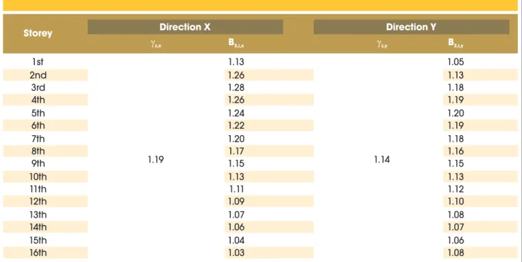
Table [3] shows the values of gz (the only one for the whole
struc-ture) and B2(determined for each storey) obtained for the irst building analyzed (“building I”), in directions X and Y.
It can be seen in table [3] that, on several storeys of building I, the B2 coeficient exceeds the value of 1.1 both in direction X and direc -tion Y. In this way, the structure can be considered very sensitive to horizontal movement and, in this case, the global second order effects cannot be ignored. The gz coeficient provides a like clas
-siication, that is, it considers the structure as being sway structure in both directions X and Y.
Table 3 – Values of the
zand B in directions X and Y, for building I
2Storey
Direction X
Direction Y
z,xB
2,i,x
z,yB
2,i,y1st
1.19
1.13
1.14
1.05
2nd
1.26
1.13
3rd
1.28
1.18
4th
1.26
1.19
5th
1.24
1.20
6th
1.22
1.19
7th
1.20
1.18
8th
1.17
1.16
9th
1.15
1.15
10th
1.13
1.13
11th
1.11
1.12
12th
1.09
1.10
13th
1.07
1.08
14th
1.06
1.07
15th
1.04
1.06
It is worth remembering that the gz coeficient can be calculated
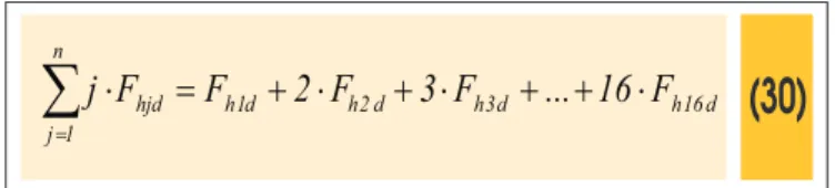
from the values of B2, utilizing equation (28). Thus, it is enough to determine the ci constants for each storey, given by equation (29).
In this equation, the
∑
= ⋅ n 1 j hjd F
j portion can be written as:
(30)
d 16 h d 3 h d 2 h d 1 h n 1 j hjdF
16
...
F
3
F
2
F
F
j
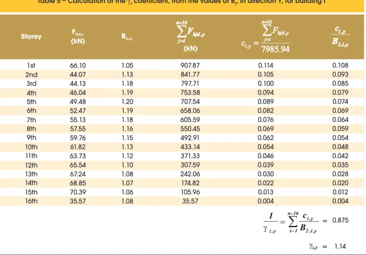
Substituting the Fhid values (design horizontal forces working on each storey of the structure), given in table [4] and [5], in equation (30), gives:
n Direction X:
j
F
3164
.
13
kN
n 1 j hjd
n Direction Y:
j
F
7985
.
94
kN
n 1 j hjd
Also considering equation (29), the
∑
= n i j
hjd
F
must be calculatedfor each storey of the structure; the results obtained are shown in
tables [4] and [5], together with all the data needed to determine the ciconstants and gz coeficient, in directions X and Y.
It can be seen in tables [4] and [5] that, as expected, the gz values
calculated from the B2 coeficients coincide with those previously obtained, shown in table [3].
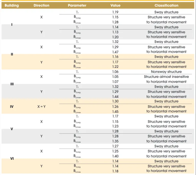
Table [6] shows the gz and B2 parameter values for other build
-ings analyzed (whose characteristics can be found in Oliveira [7]), together with the classiication of the structures, in direc -tions X and Y. However, in the case of the B2 coeficient, only the average (B2,avg) and maximum (B2,max) values of the storeys are shown. Note that, according to Silva [9], a structure can be considered almost insensitive to horizontal movement if, on all its storeys, the B2 coeficient does not exceed the value of 1.1. If B2 is greater than this value on at least one storey, the structure will be considered very sensitive to horizontal movement. In this way, classiication of the buildings is carried out by analyzing the B2,max value obtained.
Table [6] shows that, in all cases, the gz and B2 coeficients provide
the same classiication for the structures. Furthermore, the gzand B2,avg proved to be extremely close, the major difference, corre -sponding to direction X of building I, being around 3.4%. It is also worth commenting that, in the large majority of cases B2,avg was lower than gz.
Table 4 – Calculation of the
zcoefficient, from the values of B , in direction X, for building I
2Storey
F
hid,x(kN)
B
2,i,x
16 n
i j hjd,x
F
(kN)
3164
.
13
16 , ,
n i j hjdx xi
F
c
2i,,xx , i
B
c
1st
26.19
1.13
359.71
0.114
0.100
2nd
17.46
1.26
333.52
0.105
0.084
3rd
17.48
1.28
316.06
0.100
0.078
4th
18.24
1.26
298.58
0.094
0.075
5th
19.60
1.24
280.34
0.089
0.071
6th
20.79
1.22
260.73
0.082
0.068
7th
21.84
1.20
239.94
0.076
0.063
8th
22.80
1.17
218.10
0.069
0.059
9th
23.68
1.15
195.30
0.062
0.054
10th
24.49
1.13
171.62
0.054
0.048
11th
25.25
1.11
147.12
0.046
0.042
12th
25.97
1.09
121.87
0.039
0.035
13th
26.64
1.07
95.91
0.030
0.028
14th
27.28
1.06
69.26
0.022
0.021
15th
27.89
1.04
41.98
0.013
0.013
16th
14.09
1.03
14.09
0.004
0.004
n 16 1 i 2 i,,xx , i x , z
B
c
1
=
0.843
7. Final considerations
This paper sought to carry out a study of the gz coeficient, em
-ployed to indicate the need or otherwise to consider the global sec -ond order effects in the analysis of reinforced concrete structures. To conduct the study, several reinforced concrete buildings of me -dium height were processed utilizing ANSYS-9.0 [1] software. Initially, the inluence of the structural model adopted in calculating gz was evaluated. On the basis of the studies done, it was ascer -tained that less reined analyses tend to provide more conserva -tive gz values. This means that, for structures analyzed by means
of simpliied models, obtaining high gz values does not necessarily
mean signiicant second order effects. As such, on adopting simpli -ied models, it is up to the technical medium to be aware that using them can, in many cases, prove disadvantageous and uneconomi -cal, resulting in quite relevant second order effects, when in fact they should not be so.
On putting the project into practice, more sophisticated models (in which the slabs are depicted as shell elements and the eccentric -ity existing between the beam axis and the average slab plane is considered), although they involve more computer work, should be preferably be utilized, since they depict the actual behaviour of the structures more accurately and provide much lower gz values than
those obtained by more simpliied models, which leads to greater
savings and, in many cases, dispenses with carrying out analyses that consider second order effects approximately or otherwise. Next, a comparative analysis was done of the gz coeficient and the B2 coeficient, commonly employed to evaluate second order ef -fects on steel structures. To conduct the study, initially an equation relating these parameters was developed. Later, the values of gz
and B2 for several reinforced concrete buildings of medium height were calculated. From the results obtained, it was observed that the average values of the B2 (B2,avg) coeficients showed close prox -imity in relation to gz and that, in all cases, the gz and B2 parameters provided the same classiication as the structures.
However, an important aspect deserves to be highlighted concern -ing the gz coeficient: contrary to the B2 coeficient, it presents a
single value for the entire structure, although, as found in several works (Carmo [15], Lima & Guarda [16] and Oliveira [17]), second order effects suffer variations along the height of the buildings. This means that, should the gz coeficient be utilized as magniier of irst
order moments, as Oliveira [7] suggests, the inal moments at some storeys could be underestimated, and overestimated at others. Thus, a better estimate of the inal moments could be made utilizing both coeficients gz and B2, which is calculated for each storey of the structure
and whose average value is approximately gz. The magniier of the irst
order moments would then be differentiated for each storey i of the struc-ture, and given as (B2,i /B2,avg).gz. Although more speciic studies on the
Table 5 – Calculation of the
zcoefficient, from the values of B , in direction Y, for building I
2Storey
F
hid,y(kN)
B
2,i,y
16 n
i j hjd,y
F
(kN)
7985.94
16 , ,
n i j hjdy yi
F
c
2i,,yy , i
B
c
1st
66.10
44.07
44.13
46.04
49.48
52.47
55.13
57.55
59.76
61.82
63.73
65.54
67.24
68.85
70.39
35.57
1.05
1.13
1.18
1.19
1.20
1.19
1.18
1.16
1.15
1.13
1.12
1.10
1.08
1.07
1.06
1.08
907.87
841.77
797.71
753.58
707.54
658.06
605.59
550.45
492.91
433.14
371.33
307.59
242.06
174.82
105.96
35.57
0.114
0.105
0.100
0.094
0.089
0.082
0.076
0.069
0.062
0.054
0.046
0.039
0.030
0.022
0.013
0.004
0.108
0.093
0.085
0.079
0.074
0.069
0.064
0.059
0.054
0.048
0.042
0.035
0.028
0.020
0.012
0.004
2nd
3rd
4th
5th
6th
7th
8th
9th
10th
11th
12th
13th
14th
15th
16th
n 161 i 2 i,,y
y , i y , z
B
c
1
=
0.875
subject have not been done, we believe this to be very logical and rational alternative for taking into account how second order effects vary accord -ing to how high storeys in reinforced concrete build-ings are.
8. Bibliographical references
[01] ANSYS, Inc. Theory Reference (Release 9.0), 2004. [02] ASSOCIAÇÃO BRASILEIRA DE NORMAS TÉCNICAS.
NBR 6118 – Projeto de estruturas de concreto - Procedimento. Rio de Janeiro, 2007.
[03] ASSOCIAÇÃO BRASILEIRA DE NORMAS TÉCNICAS. Projeto de revisão da NBR 6118 – Projeto de estruturas de concreto. Rio de Janeiro, 2000.
Table 6 – Values obtained for the
zand B coefficients and structure classification
2Building
Direction
Parameter
Value
Classification
I
X
z1.19
Sway structure
B
2,avg1.15
Structure very sensitive
to horizontal movement
B
2,max1.28
Y
z1.14
Sway structure
B
2,avg1.13
Structure very sensitive
to horizontal movement
B
2,max1.20
II
X
z1.32
Sway structure
B
2,avg1.29
Structure very sensitive
to horizontal movement
B
2,max1.47
Y
z1.16
Sway structure
B
2,avg1.17
Structure very sensitive
to horizontal movement
B
2,max1.22
III
X
z1.06
Nonsway structure
B
2,avg1.05
Structure almost insensitive
to horizontal movement
B
2,max1.07
Y
z1.32
Sway structure
B
2,avg1.29
Structure very sensitive
to horizontal movement
B
2,max1.44
IV
X = Y
z1.30
Sway structure
B
2,avg1.26
Structure very sensitive
to horizontal movement
B
2,max1.45
V
X
z1.17
Sway structure
B
2,avg1.15
Structure very sensitive
to horizontal movement
B
2,max1.23
Y
z1.28
Sway structure
B
2,avg1.28
Structure very sensitive
to horizontal movement
B
2,max1.35
VI
X
z1.27
Sway structure
B
2,avg1.25
Structure very sensitive
to horizontal movement
B
2,max1.40
Y
z1.14
Sway structure
B
2,avg1.14
Structure very sensitive
to horizontal movement
B
2,max1.18
[04] FRANCO, M.; VASCONCELOS, A.C. Practical assessment of second order effects in tall buildings. In: COLOQUIUM ON THE CEB-FIP MC90, Rio de Janeiro. Proceedings, p.307-323, 1991.
[05] VASCONCELOS, A.C. Revisão da NB-1: O problema dos efeitos de 2ª ordem. Jornal TQS News, n.3, Out., p.10-11, 1996.
[06] VASCONCELOS, A.C. Em que casos não se deve aplicar o processo simpliicado do gz para determinação
dos efeitos de 2ª ordem?. In: SIMPÓSIO DE
ATUALIZAÇÃO SOBRE A NOVA NB-1, Belo Horizonte, 2002.
utilizados para a consideração das não-linearidades física e geométrica na análise global das estruturas de concreto armado. Belo Horizonte. Tese (Doutorado) – Escola de Engenharia da Universidade Federal de Minas Gerais, 2007.
[08] AMERICAN INSTITUTE OF STEEL CONSTRUCTION – AISC. Load and resistance factor design speciication for structural steel buildings. Chicago, 1999.
[09] SILVA, R.G.L. Avaliação dos efeitos de 2ª ordem em edifícios de aço utilizando métodos aproximados e análise rigorosa.Belo Horizonte. Dissertação (Mestrado) – Escola de Engenharia da Universidade Federal de Minas Gerais, 2004.
[10] COSTA, C.B. Considerações sobre alguns modelos clássicos para análise estrutural de edifícios de andares múltiplos sujeitos à ação de forças laterais. Belo Horizonte. Dissertação (Mestrado) – Escola de Engenharia da Universidade Federal de Minas Gerais, 2003.
[11] LOPES, F.A.F.; OLIVEIRA, R.A.; SILVA, I.M.Análises de edifícios altos considerando os pisos modelados como placa e como diafragma. In: XXX JORNADAS SUL-AMERICANAS DE ENGENHARIA ESTRUTURAL, Brasília. Anais, 2002.
[12] ASSOCIAÇÃO BRASILEIRA DE NORMAS TÉCNICAS. NBR 6120 – Cargas para o cálculo de estruturas de ediicações. Rio de Janeiro, 1980. [13] RODRIGUES JÚNIOR, S.J. Otimização de pilares de
edifícios altos de concreto armado. Rio de Janeiro. Tese (Doutorado) – Pontifícia Universidade Católica do Rio de Janeiro, 2005.
[14] ASSOCIAÇÃO BRASILEIRA DE NORMAS TÉCNICAS. NBR 6123 – Forças devidas ao vento em ediicações. Rio de Janeiro, 1988.
[15] CARMO, R.M.S. Efeitos de segunda ordem em edifícios usuais de concreto armado. São Carlos. Dissertação (Mestrado) – Escola de Engenharia de São Carlos, Universidade de São Paulo, 1995. [16] LIMA, J.S.; GUARDA, M.C.C. Comparação entre o
parâmetro alfa e o coeiciente gz na análise da
estabilidade global de edifícios altos. In:CONGRESSO BRASILEIRO DO CONCRETO, 41., Salvador. Anais, 1999.
[17] OLIVEIRA, D.M. Parâmetros de instabilidade global das estruturas de concreto armado segundo a nova NBR-6118. Belo Horizonte. Dissertação (Mestrado) –

![Figure 2 – Typical storey of building I (adapted from Costa [10])](https://thumb-eu.123doks.com/thumbv2/123dok_br/18860372.417825/6.892.61.826.173.709/figure-typical-storey-building-i-adapted-costa.webp)
![Figure 3 – Typical storey of building II (adapted from LOPES et al. [11])](https://thumb-eu.123doks.com/thumbv2/123dok_br/18860372.417825/7.892.72.826.171.1127/figure-typical-storey-building-ii-adapted-lopes-et.webp)