© 2013 IBRACON
Punching shear is a brittle failure mode that may occur in slab-column connections, which may be prevented by using shear reinforcement in the slab-column connection. This paper presents comparisons between experimental results of 36 tests in internal slab-column connections with double- headed shear studs, which are largely used in North America, Europe and Asia, with theoretical results using recommendations presented by ACI 318, NBR6118, Eurocode 2 and also the Critical Shear Crack Theory (CSCT).Considering the database used it is possible to observe that ACI 318 presents conservative trends, whereas NBR 6118 showed a low coeficient of variation, but with a large number of unsafe results. Both Eurocode 2 and CSCT showed satisfactory results with Eurocode 2 presenting slightly higher performance.
Keywords: lat slabs, punching shear, double-headed studs.
A punção é uma forma de ruptura por cisalhamento que pode ocorrer em ligações laje-pilar que pode ser evitada utilizando-se armaduras de cisalhamento na ligação. Este artigo apresenta comparações entre resultados experimentais de 36 ensaios realizados em ligações laje-pilar interno, armadas com conectores de cisalhamento do tipo pino de duas cabeças, populares na América do Norte, Europa e Ásia, com resulta-dos teóricos utilizando as recomendações do ACI 318, NBR 6118, Eurocode 2, além da Teoria da Fissura Crítica de Cisalhamento (TFCC). Para o banco de dados utilizado, o ACI 318 mostrou tendências conservadoras, enquanto que a NBR 6118 mostrou baixo coeiciente de variação, mas um grande número de resultados contra a segurança. Tanto o Eurocode 2, quanto a TFCC apresentaram resultados satisfatórios, com o Eurocode 2 apresentando desempenho ligeiramente superior.
Palavras-chave: lajes lisas, punção, conectores de cisalhamento.
Punching resistance of internal slab-column
connections with double-headed shear studs
Resistência à punção de ligações laje-pilar
interno com conectores de cisalhamento
M. H. OLIVEIRA a [email protected]
M. J. M. PEREIRA FILHO b
D. R. C. OLIVEIRA c [email protected]
M. P. FERREIRA d [email protected]
G. S. S. A. MELO e [email protected]
a Professor, Departamento de Engenharia Civil, Universidade Federal de Goiás, [email protected], Catalão, Goiás, Brasil. b Engenheiro Civil, Mestrando em Estruturas, Faculdade de Engenharia Civil, Universidade Federal do Pará, Belém, Pará, Brasil. c Professor, Faculdade de Engenharia Civil, Universidade Federal do Pará, [email protected], Belém, Pará, Brasil.
d Professor, Faculdade de Engenharia Civil, Universidade Federal do Pará, [email protected], Belém, Pará, Brasil.
e Professor, Departamento de Engenharia Civil e Ambiental, Universidade de Brasília, [email protected], Brasília, Distrito Federal, Brasil.
Received: 11 Jan 2013 • Accepted: 03 Jun 2013 • Available Online: 11 Oct 2013
Abstract
1. Introduction
Flat slabs are laminated reinforced or prestressed concrete structures that are supported directly on columns. Its use is com-mon in North American, European and Asian countries. In Brazil, this constructive system begins to stand out in the market of civil construction, mainly for its greater simplicity in the execution of the forms and rebars. Such situation can lead to reductions in labor costs and in construction time, besides attributing greater lexibility in the use of the built spaces.
Punching is a brittle failure mode by shear that may occur in struc-tural elements such as slabs when submitted to concentrated loads or reactions, which may lead the structure to ruin through the progressive collapse. The punching shear resistance slab-column connection is one of the most important parameters in the design of lat slabs. During design, it is possible to reduce the intensity of the shear stresses in the slab-column connection through the lo-cated increase of the thickness of the slab by using drop panels or column capitals. Nevertheless, the best technical alternative to in-crease the punching resistance of slab-column connections is the use of shear reinforcement. Among the several kinds of shear re-inforcements available, stand out the double-headed studs, which are very popular nowadays in constructions with lat slabs, mainly due to its eficient mechanical anchorage provided by the heads, which are forged to the rebars.
This paper aims to evaluate the recommendations presented by some of the main design codes for the estimation of punching re-sistance of reinforced concrete lat slabs with double-headed studs as shear reinforcement. This is performed through the compari-son of the experimental results of 36 tests on lat slabs with the theoretical results obtained according to the recommendations presented by ACI 318M [1], Eurocode 2 [2] and NBR 6118 [3]. The experimental results are also compared to those obtained using the Critical Shear Crack Theory (CSCT) as presented by Ruiz and Muttoni [4]. These comparisons are relevant especially because the last version of ACI and the recent version of ib Model Code 2010 [5] (based on CSCT) present speciic treatments for the cases of slabs with studs as shear reinforcement.
2. Shear reinforcement
In the design of a slab-column connections, if it is found that they do not meet safety limits regarding punching, its resistance may be enhanced adopting some actions, as the increase of the column section, of the slab thickness, of the lexural reinforcement ratio, of the compressive strength of concrete, or by using drop panels and column capitals. However, the increase of the column section or the use drop panels and capitals usually generate prob-lems from the architectural point of view. The increase of the slab thickness may mean a substantial elevation of the structure and foundation costs. Finally, increasing either the lexural reinforce-ment ratio or the compressive strength of concrete would have poor eficiency. Thus, when it is desirable to increase the punching resistance, one of the most practicable solutions may be the use of shear reinforcement.
The eficiency of the shear reinforcement regarding the punching re -sistance of slab-column connections relies on several aspects, like
performance that appropriate anchoring conditions are guaran-teed, being this, normally a critical point for most of the options of available reinforcements, once that slabs are slender elements. Other important aspect about the use of shear reinforcements in lat slabs refers to the practicality of its installation. The slab-column connection is submitted to high normal and shear stresses, being common the concentration of lexural bars in this area, what makes it dificult the distribution of shear reinforcements.
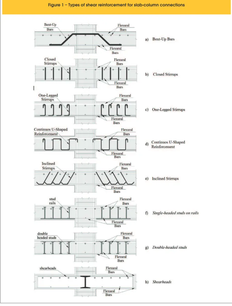
Several kinds of shear reinforcements were tested seeking to evaluate its eficiency. The irst reinforcement tested in lat slabs were bent-up bars as the ones presented in Figure 1a. This kind of reinforcement was used in tests as the ones by Graf [6], Elstner and Hognestad [7] and Andersson [8]. They can be very eficient in increasing the punching resistance, provided that precautions are taken to avoid punching failures in the area immediately after the bent-up bars. For this purpose, it might be useful to combine other kinds of shear reinforcement with bent- up bars. Broms [9] associ-ated bent-up bars in the irst two perimeters with closed stirrups and was able to avoid punching failures.
Stirrups may also be used as shear reinforcement in lat slabs, having been tested closed stirrups (Figure 1b), one-legged open stirrups (Figure 1c), continuous u-shaped reinforcement like “shear combs” (Figure 1d), inclined stirrups (Figure 1e), among others. Closed and u- shaped stirrups are of dificult use because of build -ing issues related to its assembly. One- legged stirrups showed poor anchorage in tests with lat slabs, even when adopting actions like bending its ends in 90º or 180° angles, or using horizontal bars passing inside these folds, as observed by Regan and Samadian [10]. Only inclined stirrups, as the ones used by Oliveira et al. [11] with a 60º inclination, have shown to be eficient in increasing the punching resistance.
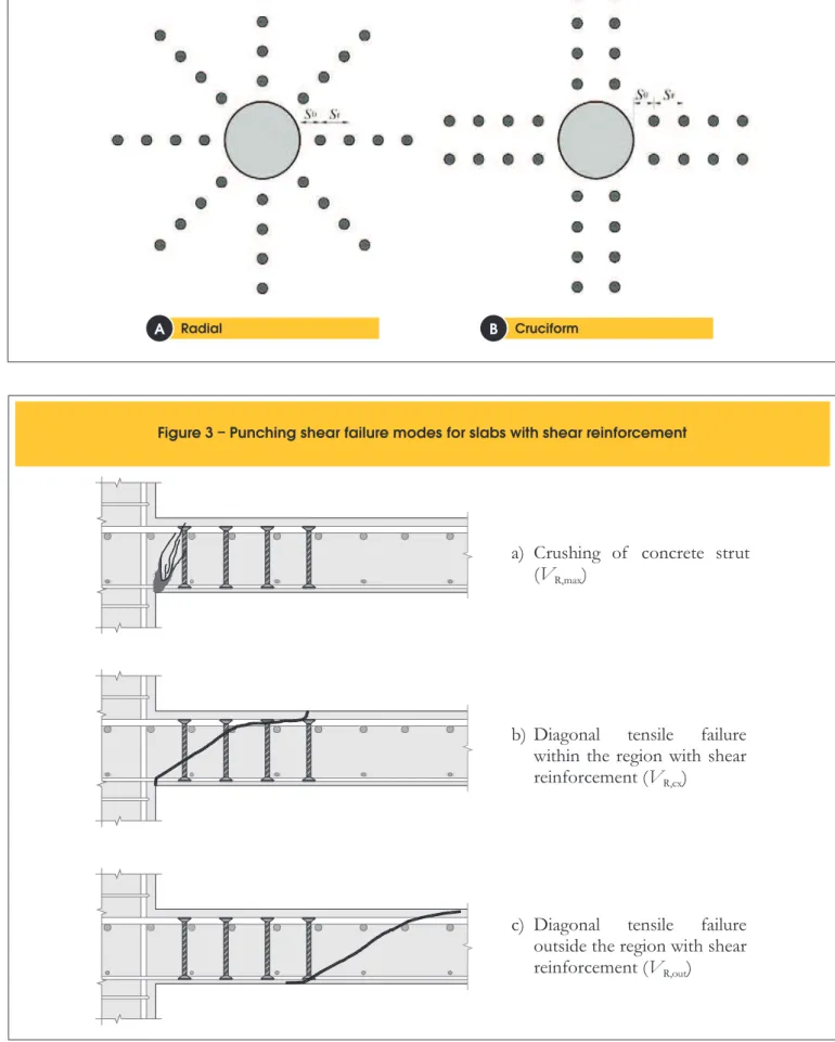
Studs (Figures 1f and 1g) have been largely used due to their good mechanical anchorage and once they are industrialized, it is easier to ensure a higher quality, and eliminate some activities of the con-struction site. Although studs are dificult to install, especially if the designer adopts a radial arrangement for them, they are the most popular shear reinforcement in the civil construction industry to-day. Figure 1h presents shear heads, which are made with steel standard sections embedded in the connection. It is a type of reinforcement considered of a high cost, normally used when there is the necessity to let large holes in the area close to the connec-tion and demand big adjusts in the lexural reinforcement around this area.
683
IBRACON Structures and Materials Journal • 2013 • vol. 6 • nº 5
Figure 2 – Different arrangements for shear reinforcements
Radial Cruciform
A
B
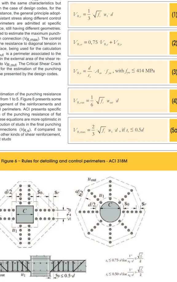
Figure 3 – Punching shear failure modes for slabs with shear reinforcement
a)
Crushing of concrete strut
(
V
R,max)
b)
Diagonal tensile failure
within the region with shear
reinforcement (
V
R,cx)
685
IBRACON Structures and Materials Journal • 2013 • vol. 6 • nº 5
inluence directly the punching shear failure mode, which may oc-cur by crushing of a diagonal strut close to the column face or by diagonal tensile inside or outside the shear reinforced zone, as illustrated in Figure 3. Experimental evidences indicate that the po-sition of punching failure cone substantially inluences the ductility of the slab-column connection after the rupture. Figure 4, adapted from Dilger and Ghali [12], shows that when the rupture occurs out of the area reinforced to shear, the ruin can be as brusque as in the case of slabs without shear reinforcement.
Other important parameter in the deinition of the punching resis -tance of slab-column connections is the distance of the irst shear reinforcement perimeter in relation to the column face (s0) and the spacing between subsequent perimeters (sr). In the case of the irst layer (s0), Eurocode 2 [2] recommends at least a distance of 0,3d. NBR 6118 [3] recommends that it is at most 0,5d, where d is the
effective depth of the slab. For the space between subsequent perimeters (sr), these codes suggest a maximum distance of 0,75d. Limitations for these values are important (see Figure 5). If the irst perimeter of studs is placed too close to the column (very small s0) their lower anchorage may be poor. The same may happen with the posterior perimeters, but in their upper anchorages, if the space be-tween layers is very high. In both cases, poor anchorage conditions may favor punching failures before the shear reinforcement yields.
3. Theoretical methods for estimation
of the punching resistence
The codes considered in this paper and the Critical Shear Crack Theory admit that the punching resistance of lat slabs with shear reinforcement should be taken as the smaller value
be-Figure 4 – Influence of the shear reinforcement in the load-displacement response - Dilger and Ghali [11]
600
400
200
0
0 15 30 45 60
P (kN)
w (mm)
wslab without shear reinforcement
failure without the region of shear reinforcement
failure within the region of shear reinforcement
P
Figure 5 – Zones with critical anchorage conditions
S
r
S
r
S
r
45
°
tween VR,cs VR,out and VR,max, corresponding to the failure modes indicated in Figure 3, but not lower than VR,c, which is the punching resistance of a slab with the same characteristics but without shear reinforcement. In the case of design codes, for the estimation of the punching resistance, the general principle adopt-ed is to assume a constant resistant stress along different control perimeters. These control perimeters are admitted at speciic distances from the column face, still having different geometries. The control perimeter u0 is used to estimate the maximum punch-ing resistance of a slab-column connection (VR,max). The control perimeter u1 is associated to the resistance to diagonal tension in the proximities of the column face, being used for the calculation of VR,c and VR,cs. Finally, uout is a perimeter associated to the resistance to diagonal tension in the external area of the shear re-inforcement, being associated to VR,out. The Critical Shear Crack Theory brings a methodology for the estimation of the punching resistance different from the one presented by the design codes.
3.1 ACI 318M
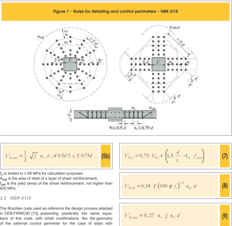
The ACI expressions for the estimation of the punching resistance are presented in the Equations from 1 to 5. Figure 6 presents some recommendation for the arrangement of the reinforcements and for the deinition of the control perimeters. ACI presents speciic expressions for the estimation of the punching resistance of lat slabs reinforced with studs. These equations are more optimistic in terms of considering the contribution of studs in the inal punching resistance of slab-column connections (VR,s), if compared to the equations presented for all other kinds of shear reinforcement, showing that ACI assumes that studs
Figure 6 – Rules for detailing and control perimeters - ACI 318M
present anchorage performance signiicantly higher than all other available shear reinforcements.
(1)
=
⋅
⋅ ⋅
,
1
3
1R c
f
cV
u d
(2)
=
⋅
+
,
0,75
, ,sR cs
V
R cV
RV
(3)
=
⋅
⋅
,s
R sw
r y
d
w
A
V
f
s
, with
f
yw≤ 414 MPa
(4)
=
⋅
⋅ ⋅
,out
1
6
uR
f
c o tV
u
d
(5a)
⋅
⋅
=
⋅
,max
2
3
1R
f
c687
IBRACON Structures and Materials Journal • 2013 • vol. 6 • nº 5
(5b)
⋅
⋅
=
⋅
,max
1
2
1R
f
cV
u d
, if 0.5
d
≤
s
r≤
0.75
d
fc is limited to ≤ 69 MPa for calculation purposes. Asw is the area of steel of a layer of shear reinforcement;
fyw is the yield stress of the shear reinforcement, not higher than 420 MPa.
3.2 NBR 6118
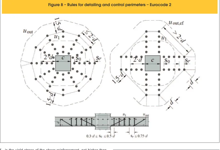
The Brazilian code used as reference the design process adopted in CEB-FIPMC90 [13], presenting practically the same equa-tions of this code, with small modiicaequa-tions, like the geometry of the external control perimeter for the case of slabs with reinforcements distributed in a radial form, which, in the case of the Brazilian code is circular. These recommendations are presented in a synthesized manner in the Equations 6 to 9 and in Figure 7. Notice that in this paper the equations are presented without the safety coeficient of 1.4, which is implicit in the expressions presented by the Brazilian code.
(6)
(
)
=
⋅
ξ
⋅
⋅ ⋅
r
⋅
1⋅
1/3,
0,18
100
R c
f
cV
u d
Figure 7 – Rules for detailing and control perimeters – NBR 6118
(7)
⎛
⎞
+
⎜
⋅ ⋅
⋅
⎜
⎝
⎠
=
⋅
,
0 75
,
,1,
5
s ,R cs w y
r
c w
R
d
efV
V
A
f
s
(8)
(
)
=
⋅
ξ
⋅
⋅
r
⋅
'1/3⋅
⋅
,
0,18
100
R out c out
V
f
u
d
(9)
=
⋅
α
⋅ ⋅ ⋅
,
0, 27
0R máx v c
V
f u d
where
fc is limited to 50 MPa for calculation purposes;
ρ is the average tensioned lexural reinforcement ratio of the slab, calculated as
r as ρ = ρ ⋅ρx y,
r r
ξ ξ = +
⎟ ⎠ ⎞ ⎜ ⎝ ⎛ − = α
≤
r≤
(
)
= ⋅ ⋅ ⋅ρ ⋅ ⋅ ⋅
= + ≤
= ⋅ +
⋅ ⋅
= ⋅
(
)
= ⋅ + ⋅ ≤ ≤
(
)
= ⋅ ⋅ ⋅ρ⋅ ⋅ ⋅
⎛ ⎞
= ⋅ ⋅ −⎜ ⎟⋅ ⋅
⎝ ⎠
,
where ρx and ρy are the ratios in the directions x and y,
respectively;
Asw is the steel area of perimeters of shear reinforcement;
ξ is the size effect, assumed as
r ρ = ρ ⋅ρ
r r
ξ as ξ = +1 200 d , wi
⎟ ⎠ ⎞ ⎜ ⎝ ⎛ − = α
≤
r≤
( )
= ⋅ ⋅ ⋅ρ ⋅ ⋅ ⋅ = + ≤
= ⋅ +
⋅ ⋅ = ⋅
( )
= ⋅ + ⋅ ≤ ≤
(
)
= ⋅ ⋅ ⋅ρ⋅ ⋅ ⋅
⎛ ⎞ = ⋅ ⋅ −⎜⎝ ⎟⎠⋅ ⋅
, with d in mm;
r ρ = ρ ⋅ρ
r r
ξ ξ = +
⎟ ⎠ ⎞ ⎜ ⎝ ⎛ − =
250 1 c v
f
α w
≤
r≤
(
)
= ⋅ ⋅ ⋅ρ ⋅ ⋅ ⋅
= + ≤
= ⋅ +
⋅ ⋅
= ⋅
(
)
= ⋅ + ⋅ ≤ ≤
(
)
= ⋅ ⋅ ⋅ρ⋅ ⋅ ⋅
⎛ ⎞
= ⋅ ⋅ −⎜ ⎟⋅ ⋅
⎝ ⎠
fyw is the yield stress of the shear reinforcement, not higher than 345 MPa for studs or 288 MPa for stirrups (steel CA-50 or CA-60).
3.3 Eurocode 2
Eurocode 2 [2] was also based on MC90. It presents recommenda-tions similar to the ones available in the Brazilian code. The main dif-ferences between the prescriptions set by this code are the limitation of the size effect value in k ≤ 2,0, the limitation of the lexural reinforce-ment ratio that effectively contributes in the punching resistance, con-sidered as ρ ≤ 2% and the determination of the effective stress in the
shear reinforcement. The equations 10 to 16 summarize the expres-sions presented by this code and Figure 8 helps in the determination of the control perimeters and in the reinforcement spacing.
(10)
(
)
=
⋅
⋅
⋅
r
⋅
1/3⋅
1⋅
,
0,18
100
R c
f
cV
k
u d
(11)
= +
1
200
d
≤
2, 0
k
Figure 8 – Rules for detailing and control perimeters – Eurocode 2
(12)
=
⋅
+
,
0,75
, ,sR cs R c R
V
V
V
(13)
⋅
⋅
=
⋅
,
1,5
sw yw ef,r
R s
d
V
A
f
s
(14)
(
)
=
⋅
+
⋅
≤
,
1,15 250 0, 25
,600 MPa
yw ef yw ef
f
d
≤
f
(15)
(
)
=
⋅
⋅
⋅
r
⋅
' 1/3⋅
⋅
,
0,18
100
,R out
k
f
c out ef689
IBRACON Structures and Materials Journal • 2013 • vol. 6 • nº 5
(16)
⎛
⎞
=
⋅
⋅
⎜
−
⎜
⋅ ⋅
⎝
⎠
,
0, 30
1
250
c 0R máx c
f
V
f
u d
Where:
ρ is the lexural reinforcement ratio calculated as
r as ρ = ρ ⋅ρx y,
r r
ξ ξ = +
⎟ ⎠ ⎞ ⎜ ⎝ ⎛ − = α
≤
r≤
(
)
= ⋅ ⋅ ⋅ρ ⋅ ⋅ ⋅
= + ≤
= ⋅ +
⋅ ⋅ = ⋅
(
)
= ⋅ + ⋅ ≤ ≤
(
)
= ⋅ ⋅ ⋅ρ⋅ ⋅ ⋅
⎛ ⎞
= ⋅ ⋅ −⎜ ⎟⋅ ⋅
⎝ ⎠
, where ρx and ρy are the reinforcements ratios in orthogonal directions
determined for strips with width equals to the side of the column plus 3·d for both sides;
ρ≤ 0,02 for calculating purposes; fc ≤ 90 MPa.
3.4 Critical shear crack theory (CSCT)
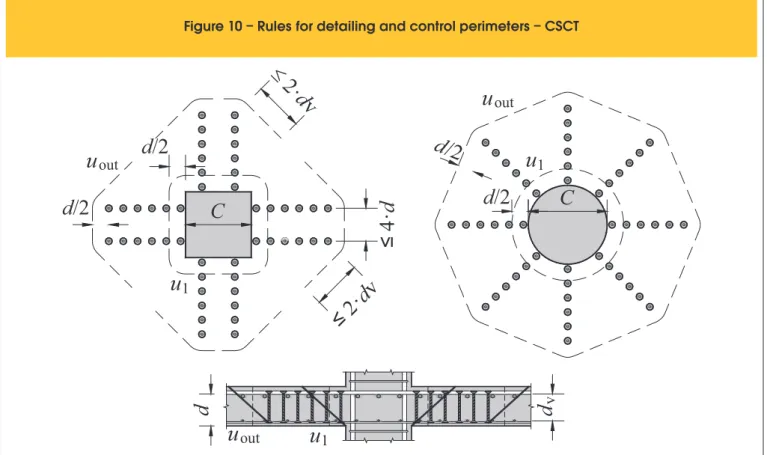
This theory is based on the idea that the punching resistance de-creases with the increase of the slab rotation, which can be ex-plained by the arising of a critical shear crack that propagates through the slab cutting the compressed diagonal that transmits the shear force to the column (see Figure 9a). The opening of this crack reduces the resistance of the compressed strut and may eventually lead to a rupture by punching. According to Muttoni and Schwartz [14] the width of this crack is proportional to the product ψ·d (see Figure 9b). The shear transmission in the critical crack is directly connected to the roughness of its supericies which is a function of the maximum size of the coarse aggregate. Based on these concepts, Muttoni [15] proposes that the shear resistance piece given by the concrete may be estimated according to the Equation 17. Figure 10 presents the position and the geometry of the control perimeters according to CSCT.
Figure 9 – Propagation of Critical Shear Crack - Adapted from Ruiz and Muttoni [4]
a)
b)
dproportional to shear crack adopted
r
qr
0r
sr
cψ
ψ.d
critical
(17)
1,
3
0
4 1 15
c R c
g g
u d
f
V
d
d
d
⋅
=
⋅
ψ
⋅
+
⋅
+
⋅
Where:
ψ is the slab rotation;
dg0 is the reference diameter of the aggregate admitted as 16 mm; dg is the maximum aggregate diameter used in the slab concrete. The resistance piece provided by the vertical shear reinforce-ments cut by the rupture supericies can be obtained through Equation 18.
(18)
,
R s sw sw
V
=
∑
A f
⋅
Where:
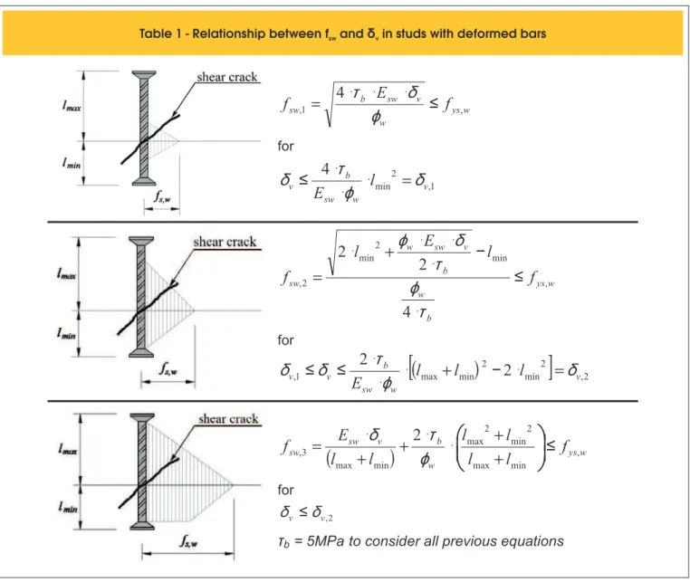
Σ is made for the shear reinforcements cut by the rupture supericies; Asw is the steel area of a layer of the shear reinforcement; fsw is the stress on each reinforcement layer, one in func-tion of the details of the shear reinforcement and of the vertical displacements δv (see Equation 19) in each reinforcement layer at the point intercepted by the rupture supericies (see Table 1).
(19)
2 2
s
v
ψ
⋅
δ
=
Where:
s is the horizontal distance measured from the face of the column up to the layer of the shear reinforcements concerned.
The punching resistance of a lat slab of reinforced concrete with vertical shear reinforcement
can be obtained through Equation 20, being this function of ψ. The relation between the applied charge (VE) and ψ rotation is expressed by Equation 21.
(20)
, , ,
R cs R c R s
V
=
V
+
V
(21)
3 2 ,
,
1,5
s ys f Es f flex
f
r
V
d E
V
⎛
⎞
ψ
=
⋅ ⋅
⋅
⎜
⎜
⎜
⎜
⎝
⎠
Where:
rs is the distance between the column axis and the null moment’s line;
fys,f is the yield stress of the lexural reinforcements; Es,f is the elasticity module of the lexural reinforcements; VE is the applied force;
Vlex is the resistance to lexion calculated through the theory of
Figure 10 – Rules for detailing and control perimeters – CSCT
2
·
d
v
d
/2
d
/2
u
u
out
C
≤
2
·
d
v
≤
4
·
d
d
C
d
/2
d
/2
u
out
u
1
u
out
u
1
1
d
v
of the compressed diagonal close to the column and can be calcu-lated by Equation 22.
(22)
, ,
R max R c
V
=
λ
⋅
V
Where:
λ is considered equals 3 for the cases of shear reinforcements well anchored like studs and 2 for the other types of shear reinforcements. In the case of ruptures occurring out of the region of the shear rein-forcements we admit that the rupture supericies will also have in -clination of 45º, but its extremity coincides with the inferior anchor-age point of the most external shear reinforcement. In practice, this implies in the reduction of the effective death of the slab (d) to an effective death (dV), as can be seen in Figure 11. The control pe-rimeter in this case is taken at a d/2 distance from the pepe-rimeter of the most external shear reinforcement layer. Equation 23 must be used for the calculation of VRout.
(23)
,
'
0
3
4 1 15
out v c
R out
g g
u
d
f
V
d
d
ψ
d
⋅
⋅
+
⋅
⋅
=
⋅
691
IBRACON Structures and Materials Journal • 2013 • vol. 6 • nº 5
Table 1 - Relationship between f and
swδ
vin studs with deformed bars
w ys w
v sw
b
f
sw
E
f
,1=
4
⋅
⋅
⋅
≤
,ϕ
δ
τ
for
1 , 2
4
min v
w sw
b
l
v
E
τ
ϕ
δ
δ
⋅
=
⋅
⋅
≤
w ys
b w
b v sw w
f
swl
E
l
f
,min 2
min
2 ,
4
2
2
≤
⋅
−
⋅
⋅
⋅
+
⋅
=
τ
ϕ
τ
δ
ϕ
for
(
)
[
]
,22 min 2
min max
1
2
,
2
v w
sw b
v
l
v
E
l
l
δ
ϕ
τ
δ
δ
⋅
+
−
⋅
=
⋅
⋅
≤
≤
(
)
ysww b v
sw
f
sw
l
E
l
l
l
l
l
f
,min max
2 min 2 max
min max
3
2
,
⎜
⎜
≤
⎠
⎞
⎜
⎜
⎝
⎛
+
+
⋅
⋅
+
+
⋅
=
ϕ
τ
δ
for
2 ,
v v
δ
δ
≤
τ
b= 5MPa
to consider all previous equations
most external layer of the reinforcements, considering 4·d as the maximum effective distance between two concentric lines of shear reinforcements;
dV is the reduced effective death.
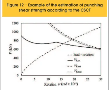
The Critical Shear Crack Theory is a graphic method for the deter-mination of the punching resistance. The calculation process be-gins with the construction of a curve that relates the shear forces with the rotation of the slab-column connection, using the terms VE
Figure 11 – Failure in the region outside the shear reinforcement - Ruiz and Muttoni [4]
and ψ. Subsequently, this graphic is added to the rupture criteria set by the equations presented above, generating curves VR,cs – ψ, VR,Max – ψ e VR,out – ψ. The intersection point of these resistance curves with the load-rotation curve deines the con -nection resistance for each one of the rupture modes. Figure 12 illustrates the graphic process used for the estimation of the resistance to punching according to CSCT.
4. Analysis of theoretical methods
The results presented and evaluated in this paper are originated from the creation of a data basis that counts on results obtained by several authors who studied the case of the lat slabs with shear reinforcement and submit to symmetric loading. It was sought in the formation of this data basis to select only results of reinforced slabs with double-headed studs or with other types of reinforce-ment which present similar mechanical behavior, once these re-inforcements are intentionally considered the most eficient in the resistance to punching due to its best mechanical anchorage. Thus, the data basis counts only on the results of 36 experimental tests. It was opted not to use results of slabs with other kinds of shear reinforcement, to evaluate the accuracy and appropriation of the hypothesis admit by the theoretical methods previously pre-sented to estimate the punching resistance in cases of slabs with shear reinforcement considered of a good anchorage. Slabs tested by Regan [16], Birkle [17], Regan and Samadian [10], Gomes and Regan [18] and Cordovil [19] were selected.
Regan [16] slabs were not published in scientiic media of public access, so these results were passed through personal corre-spondence with the author, having its proper authorial conces-sion. From the slabs tested by Birkle [17], nine slabs had shear reinforcement and three slabs were used as reference. This au-thor’s slabs are important due to the elevated thickness they had, providing valuable results in relation to the size effect. All of the se-lected slabs tested by Regan and Samadian [10] presented shear reinforcements type double-headed stud, being their results
impor-Figure 12 – Example of the estimation of punching
shear strength according to the CSCT
tested by Gomes and Regan [18], one of them did not have shear reinforcement and ten had reinforcements formed by slices of I sections, having these reinforcements mechanical behavior similar to double-headed studs. Finally, from the slabs tested by Cordovil [19], three slabs had shear reinforcement and one slab was used as reference. These slabs provided results for small thicknesses and for the use of shear reinforcement ratio relatively low.
The analyses performed in this article consisted basically of comparing the rupture load obtained in the tests with the theo-retical loads estimated by the methods presented. To evaluate the accuracy and the safety of these theoretical methods, these authors set the criterion presented on Table 2, which has as a basis the relation Vu/Vteo (being Vu the last test charge and Vteo the last load estimated by the theoretical method under evaluation). Figure 13 presents general characteristics of the slabs used in the data basis and Table 3 shows all the variables of the tested models, used as entry values in the calculations performed. Table 4 presents the results of the tests and the theoretical esti-mations, besides a simpliied statistic evaluation, considering the results average and its respective coeficient of variations. Analyzing the results of the North American code ACI 318M [1], it becomes evident that among all estimations of ultimate load, this one presented the most conservative predictions, having for the relation Vu/VACI a 1.48 average value and a 0.19 coeficient of variation. This fact is associated to the fact that this code under-estimates the contribution of the steel for the punching resistance. Comparing these expressions to consider the contribution of the ACIconcrete to the ones of Eurocode and with the ones of NBR 6118, we have VR,cACI/VR,cEC2 has a 0.85 average value and for NBR the relation VR,cACI/VR,cNBR has a 0.79 average value. It proves the conservatism of ACI in relation to the piece of con-tribution of the concrete in the punching resistance. This same conservatism is seen when compared to the relation of the steel resistance parcel VR,sACI/VR,sEC with a 0,86 average value and the relation VR,sACI/VR,sNBR with a 0.76 average value. This code also presents a strong tendency to predict ruptures in a critical perimeter out of the area of the shear reinforcement, pre-senting this kind of rupture in 89% of its predicts, besides present-ing in a general way a mistake of 45% in all predictions of the rup -ture supericies. Although ACI considers at a more appropriate form for the anchorage condition of the different types of shear reinforcement, its conservatism in relation to the resistant capacity of the materials perhaps must be reevaluated. This fact leads to
Table 2 - Criteria for evaluating V /V
u teoCriteria for
evaluating
Classification
V /V < 0,95
u teo0,95 ≤ V /V ≤ 1,15
u teo1,15 < V /V ≤ 1,30
u teoV /V > 1,30
u teo693
IBRACON Structures and Materials Journal • 2013 • vol. 6 • nº 5
Figure 13 – Details of the slabs of the database
:
:
cylinder or ti
cylinder or ti
ie causing tw
ie; (cylinders
wo loads or re
below the co
58
0
580
1250
1250
20
0
457
457
457
actions;
olumns not sh
27
50
2742 3000
200
hown)
200
200
100 545
1540 250
r
q545
h
160 230 300
1000 1500 1900 h (mm) (mm)r
100
100
154
0
59
5
15
0
595
100
120
Regan [16]
Gomes e Regan [18]; Regan and Samadian [10]
Birkle [17]
Cordovil [19]
A
C
B
Table 3 – Slabs characteristics
Author
Regan
(2009)
Regan
and
Samadian
(2001)
Cordovil
(1995)
Birkle
(2004)
Gomes
and
Regan
(1999)
Slab
(mm)
d
(mm)
c
(%)
ρ
Ø
w(mm)
s
0(mm)
s
r(MPa)
f
c(MPa)
f
ys(GPa)
E
s,f(MPa)
f
ys,w(GPa)
E
s,w(mm)
d
g(mm) Lines
A /
swLayer
2
(mm )
Perimeters
1
2
3
R3
R4
A1
A2
R5
R6
7
8
11
S1
S2
S3
S4
S5
S6
S7
S8
S9
S10
S11
S12
1
2
3
4
5
6
7
8
9
10
11
150
150
150
160
160
160
160
240
236
131
131
131
124
124
124
124
124
124
190
190
190
260
260
260
159
153
158
159
159
159
159
159
159
154
154
300
300
300
200
200
200
200
500
350
100
100
100
250
250
250
250
250
250
300
300
300
350
350
350
200
200
200
200
200
200
200
200
200
200
200
80
60
60
80
80
80
80
90
70
–
70
70
–
45
45
30
30
30
–
50
75
–
65
95
–
80
80
80
80
80
80
80
80
80
80
–
80
80
80
80
80
80
80
80
80
80
120
100
120
120
80
80
120
60
140
–
100
100
–
90
90
60
60
60
–
100
150
–
130
195
33
30
26
33
39
37
43
32
25
34
34
34
36
29
32
38
36
33
35
35
35
31
30
34
40
34
39
32
35
37
34
34
40
35
35
550
550
550
670
670
570
570
550
550
500
500
500
488
488
488
488
488
488
531
531
531
524
524
524
680
680
670
670
670
670
670
670
670
670
670
210
210
210
210
210
210
210
210
210
199
199
199
195
195
195
195
195
195
200
200
200
200
200
200
215
215
185
185
185
185
185
185
185
185
185
550
550
550
442
442
519
519
350
350
–
320
320
–
393
393
465
465
465
–
460
460
–
409
409
–
430
430
430
430
430
430
430
430
430
430
210
210
210
210
210
210
210
210
210
–
199
199
–
200
200
200
200
200
–
200
200
–
200
200
–
205
205
205
205
205
205
205
205
205
205
20,0
20,0
20,0
20,0
20,0
20,0
20,0
20,0
20,0
19,0
19,0
19,0
14,0
14,0
14,0
14,0
14,0
14,0
20,0
20,0
20,0
20,0
20,0
20,0
20,0
20,0
20,0
20,0
20,0
20,0
20,0
20,0
20,0
20,0
20,0
1,45
1,76
1,76
1,26
1,26
1,64
1,64
0,72
0,67
0,85
0,85
0,85
1,53
1,53
1,53
1,53
1,53
1,53
1,29
1,29
1,29
1,10
1,10
1,10
1,27
1,32
1,27
1,27
1,27
1,27
1,27
1,27
1,27
1,31
1,31
10
10
12
12
12
10
10
14
14
–
6,3
6,3
–
10
10
10
10
10
–
10
10
–
13
13
–
6
7
8
10
10
12
12
12
6
7
10
12
10
8
8
8
8
12
8
–
8
8
–
8
8
8
8
8
–
8
8
–
8
8
–
8
8
8
8
8
8
8
8
8
8
785
942
1.131
905
905
628
628
1.847
1.232
–
249
249
–
567
567
567
567
567
–
567
567
–
1.013
1.013
–
226
301
402
628
628
905
905
940
226
301
4
6
5
4
6
6
4
4
5
–
3
3
–
6
6
5
7
7
–
5
6
–
5
6
–
2
2
3
4
4
5
6
9
5
5
safety levels considered exaggerated and which may lead to an anti-economics dimensioning.
Evaluating NBR 6118 [3] and having as a basis the classiication of the normative performance level presented in Table 4, it is pos-sible to say that this code presents very accurate average results. Although it has presented relation Vu/VNBR with a 0.97 general average and a 0.11 coeficient of variation, the safety level of the equations of NBR 6118 is questionable, once that for 64% of the slabs its results were against safety, with the code estimating a
695
IBRACON Structures and Materials Journal • 2013 • vol. 6 • nº 5
rupture in 74% of the slabs with shear reinforcement which are in the data basis. This same behavior was also noticed by Ferreira [17] and is associated to the conservatism of the prescriptions for
Table 4 – Relationship between the experimental results and theoretical methods
Author
Regan
(2009)
Codovil
(1995)
Regan and
Samadian
(2001)
Birkle
(2004)
Gomes
and Regan
(1999)
Slab
V
uNBR -2007
EC2 -2004
ACI -2008
TFCC
(kN)
surface
Failure
Failure
surface NBR
Surface EC2
Failure
Surface ACI
Failure
Surface TFCC
Failure
V/V
NBRV/V
EC2V/V
ACIV/V
TFCC1
2
3
7
8
11
14
Ref - reference slab (without shear reinforcement); in – failure surface position within the region of shear reinforcement; out - failure surface position outside the region of shear reinforcement; Max - failure by crushing the concrete strut; flex - flexural strength;
Note: all reference slabs failure by punching.
Average
C.V
0,97
0,11
0,12
1,13
1,48
0,19
0,15
1,16
R3
R4
A1
A2
R5
R6
S1
S2
S3
S4
S5
S6
S7
S8
S9
S10
S11
S12
1
2
3
4
5
6
7
8
9
10
11
881
1.141
1.038
320
400
412
302
850
950
1.000
950
1.440
1.280
435
480
513
526
518
522
874
1.070
1.025
1.335
1.626
1.687
560
693
773
853
853
1.040
1.120
1.200
1.227
800
907
in
fc/out
fc/in
Ref.
in
in
in
Ref.
in
in
in
Ref.
in
in
in
out
out
out
in
out
flex
Ref.
in
in
out
out
out
Ref.
in
in
Ref.
in
in
Ref.
in
in/out
out
out
out
out
out
out
in
in
0,85
0,94
1,00
0,96
0,98
1,01
0,86
0,85
0,90
0,88
0,93
0,95
0,91
0,97
0,92
0,91
0,93
0,93
0,96
0,92
0,84
0,98
0,77
0,86
0,82
0,88
1,14
1,10
1,03
1,01
1,01
1,13
1,20
0,92
1,16
1,18
1,02
1,13
1,22
1,08
1,05
1,09
1,07
1,04
1,10
1,08
1,03
1,09
1,02
1,11
1,19
1,12
1,21
1,21
1,18
0,94
0,98
1,06
0,78
1,00
0,90
0,94
1,26
1,21
1,27
1,24
1,23
1,38
1,48
1,09
1,28
1,31
1,45
1,71
1,73
1,36
1,42
1,47
1,30
1,44
1,39
1,50
1,42
1,08
1,05
1,30
1,24
1,10
1,67
1,67
1,67
1,12
1,29
1,28
0,88
1,24
1,03
1,16
1,64
1,64
1,98
1,77
2,07
2,02
1,90
1,70
1,58
1,68
0,98
1,17
1,09
1,05
1,11
1,16
0,97
1,05
1,12
1,20
1,10
1,07
0,88
1,13
1,06
1,04
1,11
1,10
1,08
1,00
0,91
1,10
0,84
0,93
1,00
1,02
1,19
1,22
1,36
1,21
1,44
1,43
1,53
1,49
1,39
1,52
out
out
out
out
out
out
in
out
out
Ref.
out
out
out
out
out
Ref.
out
in
Ref.
out
in
Ref.
in
in
out
out
out
out
out
out
in
in
out
out
out
Ref.
in
in
out
Ref.
in
in
out
out
out
out
in
out
out
Ref.
out
out
out
out
out
Ref.
out
in
Ref.
out
out
Ref.
in
in
out
out
out
out
out
out
in
in
out
out
out
out
out
out
out
out
out
Ref.
out
out
out
out
out
Ref.
out
in
Ref.
out
in
Ref.
out
out
out
out
out
out
out
Max
in
out
out
out
out
in
in
in
in
out
in
Ref.
in
in
out
out
out
Ref.
in
in
Ref.
in
in
Ref.
in
in
in
in
in
in
in
in
in
in
reinforce-ments layer of 1.5d to 2d and altering the criterion of the maximum transversal spacing between layers (st,max) of 2d to 4d. The au-thor observed that such actions would substantially improve the predictions for VR,out, being more appropriate to the experimen-tal evidences, but require adjusts also in the equation for VR,cs, otherwise, this code would be thought of presenting a substantial number of results against safety. An alternative that may solve this problem would be to reduce the adjust coeficient of the Equation 10 from 0.18 to 0.16 as discussed by Sacramento et al. [21] and also by Oliveira [22].
The Critical Shear Crack Theory (CSCT) showed satisfactory re-sults, having a 1.16 average value for the relation Vu/VTFCC and a 0.15 coeficient of variation, with performance similar to EC2. In relation to the prediction of the rupture supericies, on the contrary of the other codes, CSCT presented a tendency to predict rup-tures inside the area of the shear reinforcements, predicting this kind of rupture in 74% of the slabs of the data basis. Even though its predicts for the slabs rupture mode was inappropriate, being wrong about the position of the rupture supericies in 37% of the evaluated cases.
5. Conclusions
This paper discusses the use of shear reinforcements as one of the best manners to increase the punching resistance and the duc-tility of slab-column connections. It also presents in a succinct way the recommendations of the codes ACI 318, NBR 6118 and Euro-code 2, besides the Critical Shear Crack Theory. It was made a small data basis with experimental results of tests in 36 slabs with double-headed studs or similar shear reinforcements, comparing these results with the theoretical ones obtained using the codes and CSCT.
Even considering that the data basis is limited due to the lack of tests with slabs with this kind of shear reinforcement, it is possible to observe that the recommendations presented by ACI may be conservative for the cases of slabs with shear reinforcements with good anchorage. The average of Vu/VACI was 1.48 and the coef-icient of variation was 0.19, substantially superior to the ones ob-served in the other theoretical methods. This elevated coeficient of variation was already expected once that ACI ignores important parameters in its equations, as the contribution of the lexion rein -forcements, besides the reduction of the resistant tension with the increase o the useful height (size effect).
NBR 6118 showed that, despite presenting a 0.97 average results of Vu/VNBR and a 0.11 coeficient of variation, the lowest among the evaluated methods, its equations present a strong tendency of results against safety. At the same moment the low coeficient of variation indicates that the parameters used in its equations present a good correlation with the tendency of the experimen-tal results, the necessity of some adjustments becomes evident to avoid this tendency of insecure results, as it has already been highlighted by Ferreira [20] and Sacramento et al. [21].
Eurocode 2, by limiting k and r values, reduced the tendency of insecure results observed for NBR 6118, presenting the best re-sults among the theoretical methods evaluated. For the small data basis presented, Eurocode 2 presented a 1.13 average of the rela-tion Vu/VEC2 and a 0.12 coeficient of variation. Even though, it
effect and for the lexural reinforcement ratio, considering techni -cally more appropriate to perform adjusts in the coeficients of the formulations.
Brief comments on the Critical Shear Crack Theory must be made. This method showed sensible to the several variables common in the dimensioning of the lat slabs and presented re-sults near the ones of EC2, although slightly more con-servative for the data basis in question. In spite of its equa-tions presenting, apparently, a strong empiric basis, the method is very well grounded and explains at a satisfactory mode the punching phenomenon. However, it must be emphasized that, as the method considers that the part of the slab external to the critical shear crack presents only rotations of rigid body and that the sliding of the supericies in the area of this crack does not occur, the method presents the tendency of estimating deforma-tions and, consequently, superior stresses the most distant from the column the shear reinforcements are, when in reality the effect experimentally observed is the opposite. In practice, this may lead to inappropriate results for values of s0 and sr near the minimum.
6. Acknowledgements
The authors would like to thank CNPq and CAPES for the inancial support in all stages of this research.
7. References
[01] ACI Committee 318, Building Code Requirements for Structural Concrete (ACI 318-08) and Commentary, American Concrete Institute, Farmington Hills,
Michigan, 2008.
[02] Eurocode 2, Design of Concrete Structures—Part 1-1: General Rules and Rules for Buildings, CEN, EN 1992-1-1, Brussels, Belgium, 2004, 225 pp. [03] ASSOCIACAO BRASILEIRA DE NORMAS TECNICAS.
NBR 6118 – Projeto de Estruturas de Concreto. Rio de Janeiro, 2007.
[04] RUIZ, M. F.; MUTTONI, A. Applications of Critical Shear Crack Theory to Punching of Reinforced Concrete Slabs with Transverse Reinforcement. ACI Structural Journal, July- August 2009. Nº 106-S46. [05] ib Bulletins no. 65 e no. 66, Model Code 2010 – Final
draft, Volume 1, 350p, Volume 2, 370p, 2012. [06] GRAF, O..Versucheuber die Widerstandsfahigkeit
von Eisenbetonplattenunterkonzentrierter Last naheeinem Aulager. Deutscher Ausschu β fur Eisenbeton, Heft 73, Berlin, 1933, 16 pp. [07] ELSTNER, R. C., e HOGNESTAD, E., Shearing
Strength of Reinforced Concrete Slabs. Journal of the American Concrete Institute, Proceedings, V. 53, No. 1, Jul. 1956, pp. 29-58.
[08] ANDERSON, J. L., Punching of Concrete Slabs with Shear Reinforcement. Royal Institute of Technology, Bulletin, No. 212, KTH Stockholm, Sweden, 1963, 59p.
697
IBRACON Structures and Materials Journal • 2013 • vol. 6 • nº 5
[10] REGAN, P. E., SAMADIAN, F., Shear Reinforcement against Punching in Reinforced Concrete Flat Slabs, The Structural Engineer, V. 79, No. 10, May 2001,
pp. 24-31.
[11] OLIVEIRA, D. R., MELO, G. S., REGAN, P. E., Punching Strengths of Flat Plates with Vertical or Inclined Stirrups. ACI Structural Journal, V. 97, No. 3, May-June 2000, pp. 485-491.
[12] DILGER, W.H., and GHALI, A., Shear Reinforcement for Concrete Slabs, ASCE Journal of Structural Division, Proceedings, V. 107, No. ST12, Dec. 1981, pp. 2403- 2420.
[13] Comité Euro-International du Béton. CEB-FIP Model Code 1990. London, Thomas Telford, 1993. [14] MUTTONI, A., and SCHWARTZ, J., Behaviour of
Beams and Punching in Slabs without Shear Reinforcement, IABSE Colloquium, V. 62, Zurich, Switzerland, 1991, pp. 703-708.
[15] MUTTONI, A., Punching Shear Strength of Reinforced Concrete Slabs without Transverse Reinforcement, ACI Structural Journal, V. 105, No. 4, July-Aug. 2008, pp. 440-450.
[16] REGAN, P. E., Report on tests of reinforced concrete lat slabs with double-headed studs. Correspondência pessoal com o autor. 2009.
[17] BIRKLE, G., Punching of Flat Slabs: The Inluence of Slab Thickness and Stud Layout. PhD Thesis. Department of Civil Engineering, University of Calgary, Calgary, Canada, 2004, 152 pp.
[18] GOMES, R. B. e REGAN, P. E., Punching Resistance of RC Flat Slabs with Shear Reinforcement. Journal of Structural Engineering, 1999, 684-692.
[19] CORDOVIL, F. A. B. Punção em Placas de Concreto Armado. Tese de Doutorado, Departamento de Engenharia de Estruturas e Fundações, Escola Politécnica da Universidade de São Paulo, 1995, 393p. [20] FERREIRA, M. P. (2010). Punção em Lajes Lisas de Concreto Armado com Armaduras de Cisalhamento e Momentos Desbalanceados. Tese de Doutorado em Estruturas e Construção Civil, Publicação E.TD – 007 A/10 Departamento de Engenharia Civil e Ambiental, Universidade de Brasília, Brasília, DF, 275p.
[21] SACRAMENTO, P.V.P; FERREIRA, M.P; OLIVEIRA, D.R.C; MELO, G.S.S.A, Punching strength of reinforced concrete lat slabs without shear reinforcement. IBRACON Structures and Materials Journal. 2012. vol. 5, nº 5.
[22] OLIVEIRA, M. H. (2013). Punção Em Lajes Lisas Com Armadura de Cisalhamento Submetidas a
![Figure 4 – Influence of the shear reinforcement in the load-displacement response - Dilger and Ghali [11]](https://thumb-eu.123doks.com/thumbv2/123dok_br/18860130.417787/5.892.65.837.140.488/figure-influence-shear-reinforcement-displacement-response-dilger-ghali.webp)
![Figure 9 – Propagation of Critical Shear Crack - Adapted from Ruiz and Muttoni [4]](https://thumb-eu.123doks.com/thumbv2/123dok_br/18860130.417787/9.892.456.835.174.273/figure-propagation-critical-shear-crack-adapted-ruiz-muttoni.webp)