Nanocrystalline Magnetic Materials Obtained by Flash Annealing
R.K. Murakami, V. Villas-Boas*
Universidade de São Paulo, Instituto de Física, C. P. 66318, 05315-970 São Paulo - SP, Brazil
*e-mail: [email protected]
Received: February 27, 1998; Revised: March 1, 1999
The aim of the present work was to produce enhanced-remanence nanocrystalline magnetic material by crystallizing amorphous or partially amorphous Pr4.5Fe77B18.5 alloys by the flash
annealing process, also known as the dc-Joule heating process, and to determine the optimal conditions for obtaining good magnetic coupling between the magnetic phases present in this material. Ribbons of Pr4.5Fe77B18.5 were produced by melt spinning and then annealed for 10-30 s at temperatures 500 - 640 °C by passing current through the sample to develop the enhanced-rema-nence nanocrystalline magnetic material. These materials were studied by X-ray diffraction, differential thermal analysis and magnetic measurements. Coercivity increases of up to 15% were systematically observed in relation to furnace-annealed material. Two different samples were carefully examined: (i) a sample annealed at 600 °C which showed the highest coercive field Hc and
remanence ratio Mr/Ms and (ii) a sample annealed at 520 °C which showed phase separation in the
second quadrant demagnetization curve. Our results are in agreement with other studies which show that flash annealing improves the magnetic properties of some amorphous ferromagnetic ribbons.
Keywords: nanocrystalline magnetic materials, flash annealing permanent magnets
1. Introduction
High performance permanent magnets require a mate-rial which can simultaneously have high remanence Mr,
high Curie temperature Tc and strong uniaxial anisotropy.
Strnat and co-workers1 developed the well-known SmCo5
based material from which the first high performance per-manent magnet was prepared and due to which, for exam-ple, the advent of the walkman was made possible. This material is made from aligned single crystal powders and presents the highest magnetocrystalline anisotropy of all known magnetic materials (HA = 530 - 550 kOe)2 which
gives it high values for the coercive field (Hc = 20-40 kOe)
and energy product ((BH)max≈ 25 MGOe). The coercive
field Hc and the energy product (BH)max are usual measures
of quality for permanent magnets. The coercive field Hc is
defined as the reverse field required to reduce the magneti-zation to zero. The (BH)max is inversely proportional to the
volume of permanent magnet material needed to produce a magnetic field in a given volume of space. So, the higher the (BH)max , the smaller the permanent magnetic device
that can be produced. Despite the exceptional properties of this material, researchers continued to search for a rare-earth - iron phase to replace the SmCo5 based material,
because both samarium and cobalt are expensive and also because of instability in the cobalt market and the limited availability of separated samarium. In 1983, the ternary phase Nd2Fe14B was announced at the same time in Japan3
and in the United States4. The Nd2Fe14B phase is tetragonal
and is magnetically uniaxial along the c-axis with Nd and Pr which are less expensive than Sm. The Nd2Fe14B phase
also shows a saturation magnetization of about 16 kG (due to the high iron content) which allow us to estimate values of 64 MGOe for (BH)max.
The high coercivity of NdFeB-type permanent magnet materials results, on the one hand, from the high anisotropy of the Nd2Fe14B hard phase and, on the other hand, from
phases. Typical average grain sizes are: 3 - 10 µm for sintered magnets, 100 nm - 1 µm for melt-spun magnets and 300 nm - 1 µm for mechanically alloyed magnets.
Besides looking for different production techniques and suitable annealing treatments which may lead to optimal microstructures, the choice of an adequate alloy composi-tion is desirable. The addicomposi-tion of various dopant elements to NdFeB magnets has also improved the magnet charac-teristics by changing the intrinsic magnetic properties of the main phase and the microstruture. For example: the substi-tution of Co for Fe increases the Curie temperature Tc; the
substitution of Dy or Pr for Nd in the NdFeB magnets modifies the intrinsic magnetic properties of the main phase Nd2Fe14B increasing the anisotropy field HA and
conse-quently the Hc; the addition of Ga, Al or Cu increases the
viscosity of the intergranular nonmagnetic phase (during the liquid phase sintering process) that helps the magnetic decoupling of the grains.
Despite their magnetic and cost advantages, the NdFeB magnets have suffered because of their poor intrinsic cor-rosion resistance, since under humidity and temperature the Nd-rich intergranular phase transforms into Nd(OH)3. One
solution is to decrease the Nd content, so the lower rare-earth content results in a better corrosion resistance of the magnets, because of the smaller amount of Nd-rich inter-granular phase.
In the late 1980s one of the most exciting additions to permanent magnet materials resulted from the discovery of the exchange spring magnets. These magnets are nanocrys-talline materials consisting of a hard magnetic rare earth-based intermetallic, exchange-coupled to a soft magnetic phase. They have been the subject of much recent interest due to the possibility of their presenting enhanced rema-nence and large energy products in magnets containing large volume fractions of a soft magnetic phase. Enhanced remanence behavior (Mr/Ms = 0.75) was reported by
Coe-hoorn et al5,6 in melt-spun and furnace-annealed alloys with compositions around Nd4Fe78B18. This remanence value is
higher than would be expected (Mr/Ms = 0.50) for a random
collection of non-interacting particles with uniaxial anisot-ropy and it has been discussed7 in terms of two suitably dispersed and exchange-coupled ferromagnetic phases. In fact the nanocrystalline magnetic material reported by Coe-hoorn et al.5,6 is a more complex system composed of three phases: the main phase Fe3B, which is soft magnetic,
rep-resenting aproximately 73% of the system; Nd2Fe14B the
hard magnetic phase which is 15% of the system; and 12% of α-Fe.
These nanocrystalline magnetic materials have some very important characteristics expected for a permanent magnetic material: (i) nanocrystalline grains whose size is of the order of a domain wall width; (ii) high iron content which generates high saturation magnetization values and
makes the magnet much less expensive; and (iii) a low rare-earth content which leads to a better corrosion resis-tance of the magnets. In spite of these interesting properties, NdFeB nanocrystalline magnets suffer from one defect: they tend to have low Hc values which in general are smaller
than 3 kOe. In previous papers8-10 about nanocrystalline R4Fe78B18, we tried to produce small grain (high coercivity)
materials by rapid, high current crystallization of amor-phous ribbons, the so called flash annealing process. The flash annealing process, also known as dc-Joule heating process, is a non-conventional annealing technique, char-acterized by a fast release of thermal energy to the material resulting from passing a current through the sample11-14. It induces the formation of non-equilibrium phases possibly displaying better physical properties with respect to furnace annealling. In the case of nanocrystalline R4Fe78B18, we
found that flash-annealed ribbons presented higher coer-civities and higher remanence ratios than furnace-annealed ribbons, which shows that the flash annealing process en-hances some properties of the enhanced-remanence nanocrystalline magnetic material8-10.
The aim of the present work was to produce enhanced-remanence nanocrystalline magnetic material by crystal-lizing amorphous or partially amorphous Pr4.5Fe77B18.5
alloys by the flash annealing process and to determine the optimal conditions for obtaining good magnetic coupling between the magnetic phases present in this material. The results obtained here are in agreement with other studies which show that the flash annealing process improves the magnetic properties of some amorphous ferromagnetic rib-bons15-17.
2. Experiment
Partially amorphous ribbons of nominal composition Pr4.5Fe77B18.5 were produced by melt-spinning in He on a
mild steel wheel. X-ray diffraction of the as-cast ribbons with CuKα radiation showed them to be partially amor-phous. In previous papers9,10 about Pr4Fe78B18, the initial
ribbons were all partially amorphous and, even so, after the heat treatment, a good magnetic coupling was obtained for all the ribbons. From the Bragg reflection peak widths and the Scherrer equation, it was estimated that the crystallite size was of the order of 20 nm.
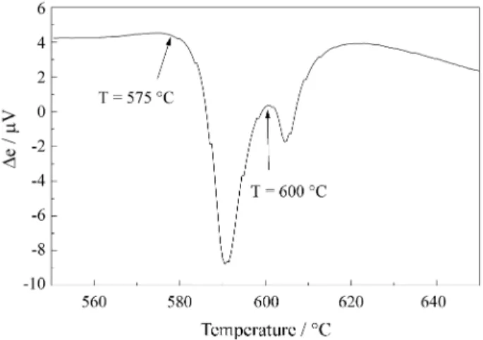
In order to determine the temperatures where the flash annealing would be carried out, differential thermal analy-sis (DTA) measurements were performed for the as-cast ribbon at 10 °C/min. The results are presented in Fig. 1 and showed crystallization events beginning at 575 °C and 600 °C, corresponding to crystallization of Fe3B and
Pr2Fe14B6.
paint for the flash annealing. The material itself was very uniform. For most of the samples, the initial resistivity was in the range 1.5 - 1.7 µΩ m, while the resistivity after flash annealing was about 1.2 - 1.4 µΩ m.
The experimental setup used for the flash annealing treatments is shown in Fig. 2. An electrical current of constant intensity supplied by a current generator flows through the sample (a ribbon of length 0.08 - 0.12 m). The behaviour of the electrical resistance may be followed in the course of the heat treatment by simultaneously measur-ing the voltage across the sample and the electrical current flowing in it which are stored by the computer. The latter measurement is most conveniently performed by using a shunt in series with the ribbon. The sample holder was maintained in a diffusion pump vacuum in order to avoid surface oxidation. As a result, no convective processes are present, and the only sources of energy transfer from the flash annealed ribbon strip to the neighboring bodies are radiative losses and thermal conduction towards the sample holder through the electrical contacts. The annealings were carried out in a vacuum of 10-5 torr for times 10 - 30 s and for temperatures 500 - 640 °C.
The sample temperature during the flash annealing was calculated from the following relation which is obtained by equating the Joule losses (i2R) with the radiated energy17,
neglecting conduction through the current and voltage leads:
Ta=(T 40+ ρ j2
P ) 1⁄4
(1)
where To is the ambient temperature, ρ is the sample
resis-tivity, j is the current density, and P is the loss parameter. The definition for P is
P =2εσB
d (2)
where ε is the sample emissivity, σB is the
Stefan-Boltzmann constant and d is the ribbon thickness. In pre-vious works9,10, considering the DTA measurements and the magnetization versus temperature measurements, we estimated for this ribbon εeff = 0.34 - 0.36. These εeff values
are approximately equal to that encountered for pure iron in this temperature range. Finally, for our samples, a resis-tance bump was observed for all flash annealings at short times, since the additional power released by crystallization of the amorphous ribbon modifies the plateau tempera-ture18. It is the presence of this resistance bump which suggests a lower limit for annealing times of about 10 s. In fact, for these Pr4.5Fe77B18.5 samples the resistance bump
lasts for about 8 s, as shown in Fig. 3. For this reason we performed flash annealings during intervals of 30 s trying to assure that the crystallization process had been com-pleted.
3. Results and Discussion
In order to determine the quality of the flash-annealed samples we did a careful study of all samples annealed at
Figure 2. Experimental setup for the flash annealing process.
Figure 1. DTA measurement at 10 °C/min for ribbon Pr4.5Fe77B18.5 showing crystallization events corresponding to Fe3B and Pr2Fe14B.
temperatures 500 - 640 °C. We divided each sample into 11 pieces and we numbered them from 0 to 10 (the extremi-ties being 0 and 10). We determined the hysteresis loops of these 11 pieces from which we determined their Hc and their
specific remanence σr. (the remanence Mr, as well as any
other magnetization value of the hysteresis curve, can be obtained by multiplying σr by 4π and by the density of the
material, which is ρ = 7.23 g/cm3 for Pr
4.5Fe77B18.5). Figure
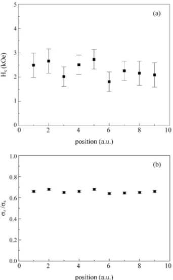
4 shows the Hc and the ratio σr / σs values (σs is the specific
saturation magnetization) for the various pieces of a sample which was flash-annealed at 640 °C. For pieces 0 and 10 there are no values of Hc and σr because they are not
magnetically coupled. This was expected since, in these current annealings, the sample ends are not really main-tained at the annealing temperature because of thermal conduction towards the sample holder through the electri-cal contacts, as it was already mentioned. For all the other characterizations we only used the pieces numbered 1 to 9.
Excellent magnetic coupling is observed for all samples annealed at temperatures 560 - 640 °C. For this temperature range there is a single well-defined peak in dσ/dH. dσ/dH is the total susceptibility χtot and is approximately equal to
the irreversible susceptibility χirr when the reversible
sus-ceptibility is small, which is the case of the materials studied in this work. In this work, the coercive field Hc is
defined as the field corresponding to the maximum of the irreversible susceptibility χirr (approximately the maximum
in dσ/dH), since Hc is intimately related to the irreversible
processes occuring in the magnetic material. This is the usual definition for those who work with coercivity mecha-nisms in permanent magnetic materials.
In Fig. 5 we show the specific magnetization σ as a function of the applied magnetic field H for a sample which was flash-annealed at 600 °C for 30 s. For this sample, which we will refer to the well-coupled sample WC, we obtained the best magnetic properties, which are Hc = 4.3
kOe and Mr/Ms = 0.72. For the samples which were
flash-annealed at temperatures lower than 560 °C, the magnetic coupling between phases deteriorated and two peaks were observed in χirr. In Fig. 5 we also show the specific
mag-netization σ as a function of the applied magnetic field H
Figure 4. Magnetic characterization for the pieces 1 to 9 of a sample which was flash-annealed at 640 °C: (a) Hc values; (b) σr / σsat values.
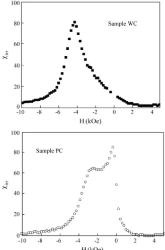
for a sample which was flash-annealed at 520 °C for 30 s and that we will refer to as the partially-coupled sample PC. In Fig. 6 we show dσ/dH ≅χirr for samples WC and PC.
The decoupling of the magnetic phases in sample PC can be seen very clearly from two peaks in χirr, the larger
corresponding to Hc = 2.8 kOe and the smaller to Hc = 0.8
kOe. In the other hand, for sample WC there is a single, well-defined peak in χirr corresponding to Hc = 4.3 kOe.
The Hc data for all the samples studied in this work are
presented in Fig. 7 as a function of the flash annealing temperature Ta , the highest value of Hc = 4.3 kOe being
obtained for Ta = 600 °C. There is a temperature range (560
- 640 °C) for which the magnetic coupling is sufficient to give a single peak in χirr as mentioned above. For
tempera-tures lower than 560 °C the phases are clearly decoupled or present low values of Hc. We did not investigate annealing
temperatures higher than 640 °C.
Although we achieved good magnetic coupling and high Hc for samples which were flash annealed at
tempera-tures 560 - 640 °C, the results obtained for the samples annealed at 560 and 580 °C suggest that the sample tem-perature which was calculated from relation (1) may not be
the real annealing temperature. The DTA results show that the crystallization event due to the hard magnetic phase Pr2Fe14B begins at 600 °C. Therefore, we must understand
why, even 40 °C below this crystallization temperature, the nanocrystalline magnetic material still shows high Hc
which indicates the presence of the Pr2Fe14B phase. This
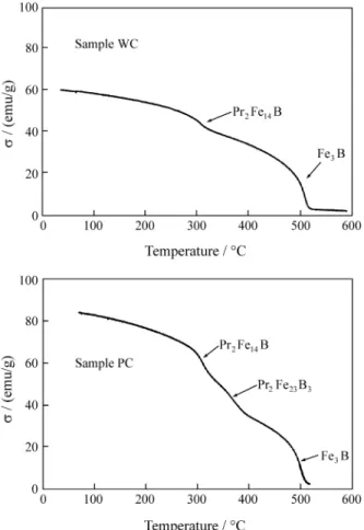
may indicate that the real annealing temperature is higher than the temperature calculated from Eq. 1. In order to clarify this question and also to complete the magnetic characterization of the sample, we performed measure-ments of the dependence of the magnetization with the temperature. These measurements can show us the mag-netic phases present in the samples. In Fig. 8 we show the thermal magnetic results for sample WC and sample PC. For sample WC we can identify two magnetic phases which are the Pr2Fe14B phase whose Curie temperature is around
300 °C and the Fe3B phase whose Curie temperature is
around 500 °C. For sample PC we can identify three mag-netic phases which are the Pr2Fe14B phase, the Fe3B phase
and the Pr2Fe23B3 whose Curie temperature is around
380 °C. Although temperatures higher than 600 °C cannot be achieved by our resistive furnace where the measure-ments are performed, we can see that, in both samples, a residual magnetization due to α-Fe, whose Curie tempera-ture is around 770 °C, can be detected.
From the measurements of dependence of the magneti-zation with the temperature we found the presence of the Pr2Fe14B phase which confirmed our suspicion that the real
annealing temperature is higher than the temperature cal-culated from Eq. 1. Looking carefully at Eqs. 1 and 2 we see that the calculated temperatures Ta would be higher if
we had a smaller emissivity ε. However, determining the emissivity of this material is not a straightforward and trivial thing to do. Standard handbooks19 show that the emissivity of iron varies with temperature and the wav-elenght (at T = 800 °C if λ = 0.65µm ε = 0.37 and if λ = 1.2 µm ε = 0.29). No data is avaiable for praseodymium or
Figure 6. Irreversible susceptibility χirrvs. applied field H for samples WC and PC, flash-annealed at 600 and 520 °C respectively for 30 s.
boron and, therefore, we are unable to estimate an average value for the emissivity of our material. What is more, a change of 0.06 in the emissivity can change the calculated temperature Ta by 40 °C, exactly the difference we need to
explain the presence of the Pr2Fe14B phase in a sample
flash-annealed at 560 °C.
The problem of determining accurately the annealing temperature remains. One procedure which could be used at present would be to present the properties of the material as a function of the annealing current without specifying the temperature. This procedure has been used by some researchers, since they are more interested in the improve-ment of the proprietiers due to thermal treatimprove-ment rather than the real temperature where the thermal treatment was per-formed20.
Finally, it is useful to try to understand why Hc is higher
in the flash-annealed materials than in the conventionally annealed ones. For that we could say something about the microstructure of the ribbons. In previous works8-10 we showed that the flash annealing of Nd4Fe78B18 results in a
phase distribution which is different from that encountered in materials prepared by conventional furnace anneals. X-ray diffraction and Mössbauer spectroscopy data showed
that flash annealing resulted in significant amounts of Nd2Fe23B3, a metastable cubic phase, and reduced
quanti-ties of α-Fe. TEM measurements21 on a ribbon of furnace-annealed Nd4Fe78B18 showed the presence of a matrix
phase consisting of 20 - 30 nm equiaxed grains with Fe/Nd = 17 - 19.6. Also observed was a second phase precipitate consisting of large (≈ 60 - 100 nm) grains with Fe/Nd = 43.8. Electron diffraction indicated an interplanar spacing close to that of α-Fe. For flash-annealed Nd4Fe78B18
showing phase separation, the matrix phase consisted of 30 -50 nm equiaxed grains. In this case, the second phase precipitate had a glassy-like morphology. For a ribbon of Nd4Fe78B18 whose hysteresis loop showed good coupling
of the magnetic phases, the large α-Fe grains were com-pletely absent and only the ≈ 20 nm equiaxed grains were observed. If we suppose that the large α-Fe grains facilitate magnetization inversion in furnace-annealed material, then their elimination in well-coupled flash-annealed samples would explain the increased Hc observed for both
Nd4Fe78B18 and Pr4Fe78B18. On the other hand,
flash-an-nealed Nd4Fe78B18 showed a significantly higher
rema-nence ratio (Mr/Ms = 0.83) than the furnace-annealed
material (Mr/Ms = 0.74). For Pr4Fe78B18 Mr/Ms = 0.77 for
both furnace and flash annealed samples9,10. Thus we can-not assume that the same microstructural differences exist between furnace and flash annealed Pr4Fe78B18 and for our
Pr4.5Fe77B18.5. Further microstructural investigations such
as TEM and AFM in our Pr4.5Fe77B18.5 are necessary.
5. Conclusions
We have used the flash annealing process to crystallize partially amorphous ribbons of Pr4.5Fe77B18.5 producing
enhanced-remanence nanocrystalline magnetic material. The optimal conditions for obtaining good magnetic cou-pling between the magnetic phases present in this material were established. The coercive field Hc for these
flash-an-nealed material increases up to 15% compared to the values reported in the literature to furnace-annealed material9 showing that this kind of current treatment really generates materials with better magnetic properties with respect for conventionally annealed ones. Then we can conclude that our results are in agreement with other studies which show that flash annealing improves the magnetic properties of some amorphous ferromagnetic ribbons.
Acknowledgements
The authors acknowledge S.A. Romero for helping with the preparation of the melt-spun ribbons; F.P. Missell for useful conversations and for the careful reading of the manuscript; and the financial support of FAPESP, CNPq, and FINEP.
References
1. Strnat, K.; Hoffer, G.; Olson, J.; Ostertag, W.; Becker, J.J. J. Appl. Phys., n. 38, p. 1001, 1967.
2. Campos, M.F.; Landgraf, F.J.G.; Saito, N.H.; Romero, S.A.; Neiva, A.C.; Missell, F.P.; Obrucheva, E.V.; Jalnin, B.V.; de Morais, E.; Gama, S. J. Appl. Phys., n. 84, p. 368, 1998.
3. Sagawa, M.; Fujirama, S.; Yamamoto, H.; Hiraga, K.
IEEE Trans. Magn., n. 20, p. 1584, 1984.
4. Croat, J.J.; Herbst, J.F.; Lee, R.W.; Pinkerton, F.E. J. Appl. Phys., n. 55, p. 2079, 1984.
5. Coehoorn, R.; de Mooij, D.B.; Duchateau, J.P.W.B.; Buschow, K.H.J. J. de Phys., n. 49, p. C8-669, 1988. 6. Coehoorn, R.; de Mooij, D.B.; de Waard, C. J. Magn.
Magn. Mater., n. 80, p. 101, 1989.
7. Kneller, E.F.; Hawig, R. IEEE Trans. Magn., n. 27, p. 3588, 1991.
8. Altoé, M.V.P.; Lancarotte, M.S.; Rechenberg, H.R.; Missell, F.P.; González, J.M. IEEE Trans. Magn., n. 31, p. 3614, 1995.
9. Villas-Boas, V., Romero, S.A.; Missell, F.P. Magnetic Anisotropy and Coercivity in Rare-Earth Transition Metal Alloys, Missell, F.P.;Villas-Boas, V.; Rechen-berg, H.R.; Landgraf, F.J.G., eds, World Scientific, Singapore, 31, 1996.
10. Villas-Boas, V.; Romero, S.A.; Missell, F.P. J. Appl. Phys., n. 81, p. 4434, 1997.
11. Yavari, A.R.; Barrue, R.; Harmelin, M.; Perron, J.C.
J. Magn. Magn. Mater., n. 69, p. 43, 1987.
12. Kulil, T.; Matyja, H. Mater. Sci. Eng.A, n. 133, p. 232, 1991.
13. Gibbs, M.R.J.; Lee, D.H.; Evetts, J.E., IEEE Trans. Magn., n. 20, p. 1373, 1984.
14. Matyja, H.; Zaluska, A. Philos. Mag. B, n. 61, p. 701, 1990.
15. Warlimont, H. Rapidly Quenched Metals, Steeb, S.; Warlimont, H., eds, North-Holland, Amsterdam, p. 1599, 1985.
16. Luborsky, F.E. Amorphous Metallic Alloys, Lubor-sky, F.E., ed., Butterworths, London, 1, 1983. 17. Allia, P.; Tiberto, P.; Baricco, M.; Vinai, F. Rev. Sci.
Instrum., n. 64, p. 1053, 1993.
18. Knobel, M.; Allia, P.; Gómez-Polo, C.; Chiriac, H.; Vázquez, M. J. Phys. D: Appl. Phys., n. 28, p. 2398, 1995.
19.Smithells Metals Reference Book, Brandes, E.A., ed., Butterworths, London chapter 17, 1983.
20. Ferrari, E.F.; da Silva, F.C.S.; Knobel, M. Phys. Rev. B, n. 56, p. 6086, 1997.