0103 - 5053 $6.00+0.00
* e-mail: [email protected]
Effects of the Operational Conditions on the Membrane and Electrode Properties of a
Polymer Electrolyte Fuel Cell
Raimundo R. Passos and Edson A. Ticianelli*
Instituto de Química de São Carlos, Universidade de São Paulo, CP 780, 13560-970 São Carlos - SP, Brazil
Os efeitos das condições operacionais sobre as propriedades da membrana e dos eletrodos em uma célula a combustível de eletrólito polimérico são estudados em função da temperatura da célula e dos umidificadores dos gases, da espessura da membrana, da impregnação com ácido fosfotúngstico (AFW) e da variação dos conteúdos de Nafion e Teflon nos eletrodos de difusão de gás. Um aumento da resistência da membrana ocorre quando a célula opera em temperatura igual ou superior àquela de umidificação dos gases, sendo este efeito mais aparente para membranas mais espessas. Na presença de AFW, as propriedades da membrana não se alteram significativamente com a temperatura do conjunto. No entanto, neste caso, uma menor temperatura de umidificação dos gases reagentes prejudica o desempenho dos eletrodos. Variações no conteúdo de Nafion nos eletrodos não levam a nenhum efeito significativo sobre as propriedades do sistema. Para altos conteúdos de Teflon há uma pequena diminuição da condutividade da membrana.
The effects of the operational conditions on the membrane and electrode properties on a polymer electrolyte fuel cell (PEFC) were investigated as a function of the cell and the gas humidifiers temperatures, the thickness of the membrane, the impregnation with phosphotungstic acid (PWA), and the variation of the Nafion and Teflon contents in the gas diffusion electrodes. An increase of the membrane resistance was observed when the PEFC is operated at temperatures equal or higher than those of the gas humidifiers, and this is more apparent for thicker electrolyte films. In the presence of PWA, the physicochemical properties of the membrane do not appreciably change with temperature. However, in this case, a lower humidification temperature affects the electrode performance. Changes on the Nafion loading in the electrodes do not lead to any significant effect in the electrode and membrane properties. For high Teflon contents there is a small lowering of the membrane conductivity.
Keywords: polymer electrolyte fuel cell, membrane, gas diffusion electrode, water transport
Introduction
Polymer electrolyte fuel cells (PEFC) have attracted enormous attention as promising energy-conversion devices for stationary and mobile applications due to the possibility of attaining high power density and high energy conversion efficiency. Researches on this system involve fundamental aspects related to the water transport in the membrane and to the fuel cell reactions,1 practical aspects related to the
optimization of the structure, composition and operational conditions of the gas diffusion electrodes,1-3 and
technological aspects related to water management and the engineering of operational sized fuel cell modules.4,5
In recent years the water transport problem in the polymer electrolyte has been the subject of several experimental and theoretical studies.6-20 Under usual
operational conditions, the humidification of the membrane is maintained by the water vapor contained in the reactant gases and by the water generated by the electrochemical reaction in the cathode side. While the cell is in operation, due to an electro-osmotic dragging effect water is carried from anode to cathode together with the protons that carry the current through the membrane.8-10
This, together with the water produced by the electro-chemical reaction, builds a higher water content on the cathode side, which promotes a back transport to the anode.8-22 Under a steady state condition, the water
dragging coefficient (
n
do) can be ca. 1 water molecule/ proton for a fully hydrated membrane in equilibrium with liquid water at 50 oC and ca. 0.2 molecule/proton with themembrane in equilibrium with a water vapor saturated gaseous atmosphere at 80 oC.10
saturates the reactant gases may limit the proton transport inside the polymer electrolyte, becoming a limiting step of the global electro-kinetic process. However, in conditions of high humidification at which this phenomenon is usually investigated,2,3 it is often concluded that the water transport
is not an important factor affecting the fuel cell operation. This work reports results of an investigation of the effects of the operational characteristics of a polymer electrolyte fuel cell working under low humidification conditions on the electrode and membrane properties. The study takes into consideration the dependence of the electrolyte physicochemical properties with the cell and the gas humidifiers temperatures, the use of membrane with and without impregnation with phosphotungstic acid (PWA), the thickness of the membrane, and the variation of the Nafion and Teflon contents in the gas diffusion electrodes.
Experimental
The working gas diffusion electrodes were prepared by a combined filtration/painting procedure using platinum-on-carbon (Pt/C) catalysts (E-Tek), carbon powder (Vulcan XC-72, Cabot), a carbon cloth substrate (PWB-3, Stackpole), a polytetrafluoroethylene suspension (Teflon-306A, DuPont), and a Nafion solution (Aldrich, 5 wt.% in 15-20% water/low aliphatic alcohols). The electrodes were made with 20 wt.%, 0.4 mg Pt cm-2 in the
catalyst layer. Electrodes with Nafion loadings of 1.1, 1.4, 1.5, 1.7, 1.9, and 2.2 mg Nafion cm-2 in the catalyst layer
were employed. Also, the Teflon content in the diffusion layer was changed from 15 to 50 wt.%, with interval of 5 wt.%. These values were varied with consequent decrease of the carbon content in order to keep the total mass of the C + Teflon in the diffusion layer around 6 mg cm-2.
The membranes were Nafion 112, 115, 117 (DuPont, H+
form) previously submitted to two different treatments: (i) the conventional procedure in which the membrane was first purified by heating at about 70-80 oC in high-purity
water containing 3 wt.% H2O2 for about 1 h, and then four times in pure water to remove all traces of H2O2. This was followed by a similar heating treatment in H2SO4 0.5 mol L-1,
and several times in high purity water; (ii) a Nafion 117 membrane was first treated as described above and then dried under vacuum in the presence of P2O5 for 6 h, and then treated by immersion in acetic acid (80 mL) containing phosphotungstic acid (1.1 g) for 48 h at 80 oC.23
Membrane-Electrode-Assemblies (MEAs) were prepared by first placing a pair of electrode in both sides of the Nafion membrane. The assembly was inserted between the plates of a hot-press preheated to 105 oC, and
then the temperature was raised to 125 oC at which a pressure
of 50 bar for 2 min was applied.
The studies were carried out in single cells (5 cm2 of
active geometric area) and the reactant gases (pure H2/O2) were externally humidified using temperature controlled humidification bottles. Testings of the single cells were conducted in a specially designed test station,24 measuring
the cell voltage as a function of the current density under atmospheric pressure and at several cell and humidifiers temperatures. At least two identical MEAs for each electrode system were tested to evaluate the repeatability of the experiments. Results indicated a dispersion on the cell potential values at a given current density not higher than ±5 mV.
Results and Discussion
In this work a theoretical analysis of the fuel cell polarization response was made for the system under low humidification conditions. The general equation used for the representation of the cell potential (E) as function of current density (j) was taken as,25
Rj
j
b
E
E
o (1)where, Eo = Ee + b log j o, E
e is the reversible potential for
the cell, b is the Tafel slope and jo is the exchange current density for the oxygen reduction reaction (ORR) in the Pt/C catalyst. R represents the total contribution for the linear polarization components, which include the charge transfer resistance of the hydrogen oxidation reaction, the resistance of the electrolyte in the cell and the linear diffusion terms associated to the diffusion limitations of the reactant gases.26,27 Equation 1 does not include
polarization terms associated with non-linear limiting diffusion components in the reactant gases. These terms are assumed to be negligible because of the use of pure hydrogen and oxygen and the absence of severe water flooding problems. As seen in a previous publication, under these conditions, the effects related to the membrane resistance anticipate any non-linear effects of gas diffusion.17
Theoretical lines for the fuel cell polarization response were generated assuming that two different Tafel slopes (b) may appear for the ORR in the Pt/C catalyst, depending on the cell potential.2,3,11 At 85 oC , these values are ca. 70 mV dec-1 for
potentials above 0.85 V, and 140 mV dec-1 for E < 0.85 V. This
In the present work, it was also considered that structural effects in the catalyst layer of the gas diffusion electrode may lead to an apparent increase of the Tafel slope at high current densities.28-32 In accordance to theoretical models, a duplication
of the true ORR value (120 mV dec-1) was assumed for
representing the limiting situation of very large electrolyte resistivity inside the catalyst layer.31,32
Since the polarization of the hydrogen electrode and the gas diffusion components are negligible when pure hydrogen and oxygen are employed, the major contribution for the R term in equation 1 is related to the membrane resistance. Sena et al.17 had developed an
expression for R using a simplified model to describe the water transport in the membrane and assuming that the water flow in the gas/anode interface is negligible. Under this condition17
W L o W Lj
j
L
j
j
R
I
(2) where,L
n
C
FD
j
o d o W W WL
(3)CW
o
is the water solubility, nd
o
the water dragging coefficient, DW the water diffusion coefficient in the membrane, and Io the conductivity and L the thickness of the membrane.17
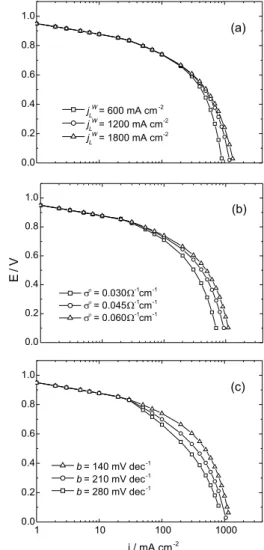
Substitution of equation 2 into 1 leads to a general equation for the description of the fuel cell polarization response. Figure 1a represents the theoretical responses for several values of jLW, while keeping o, L, and b
constants. Here, an increase of jLW represents an increase of
the water concentration in the membrane (CW
o
) and/or a decrease of the water dragging coefficient (nd
o
). Figure 1b corresponds to theoretical curves for several values of the membrane conductivity (o), for constant j
L
W, L, and b.
Finally, Figure 1c refers to several values of the second Tafel slope (b), for constant jLW, L, and o. In all cases the Eo
values were taken as 0.95 V and 1.03 V in the range of low (b = 70 mV dec–1) and high (b = 140 mV dec-1) ORR
overpotentials, respectively. The results in Figure 1 will be used below as diagnose tools for qualitative analyses of the experimental responses of the fuel cell under the several experimental conditions.
Effect of membrane impregnation with phosphotungstic acid
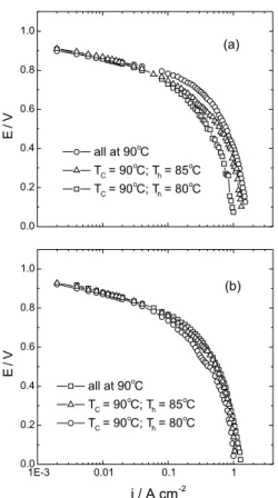
Figure 2 shows experimental polarization curves with PWA non-impregnated and impregnated Nafion 117
membranes, under several humidification conditions. Results in Figure 2a show that the decrease of the humidifiers temperatures leads in polarization responses similar to the theoretical cases represented in Figure 1b. As expected, these results show that a decrease on the humidifier temperatures leads to a decrease of the membrane conductivity (o) caused by a decrease of the
net water content in the membrane (CW
o
).
A comparison of the curves in Figures 2a and 2b shows that the presence of PWA in the membrane leads to an effect equivalent to a decrease of o, as compared to the
absence of PWA. This may be due to the polymer degradation caused by the severe conditions employed for the membrane impregnation.23 The curves in the
Figure 1. Theoretical curves generated using equations 1 and 2,
showing the E vs. j characteristics: (a) variable jL
W, b = 70 and 140 mV dec-1, o = 0.060 -1 cm-1, L = 175 m; (b) variable o, j
L W = 1200 mA cm-2, b = 70 and 140 mV dec-1, L = 175 m; (c) variable b,
jL
W= 1200 mA cm-2, o = 0.060 -1 cm-1, L = 175 m. A value of o close to 0.06 -1 cm-1 has been reported in the literature for the
presence of PWA converge to the same value of limiting current for the different humidifier temperatures. According to the theoretical results in Figure 1 this behavior is consistent with just a change in the value of the Tafel slope. This fact indicates that in the presence of PWA, the physicochemical properties of the membrane (o, C
W
o
, nd
o
) do not appreciably change with the gas humidifiers’ temperatures. However, a lower humidification temperature affects the electrode performance leading to a change in the Tafel slope due to the increased electrolyte resistivity inside the catalyst layer.31,32
Effect of the membrane thickness
Paganin et al2 had shown that the better humidification
condition for the PEFC is that in which the cell operates at 80 oC, the hydrogen humidifier at 95 oC, and the oxygen
humidifier at 85 oC. Figure 3 shows experimental
polarization curves in these conditions for membranes with thickness of 50, 125, and 175 m, for Nafion 112, 115, and
117, respectively. Figure 4 shows the polarization characteristics for the same cells under lower humidification conditions.
In all cases, thinner membranes presented better performance just because of the smaller overall electrolyte resistance. As seen in Figure 1, jLW determines a limiting
current in the polarization diagram. This, according to the theoretical formalism, appears when the water concen-tration in the membrane at the anode side tends to zero.17
Thus, the higher jLW apparent for thinner membranes
indicates that the drying of the anode occurs at higher current densities. This is a consequence of the fact that the water diffusion flow from the cathode to the anode, which in a first approximation is given by = DWCW
o
/L (equation
3), is more effective for thinner membranes.
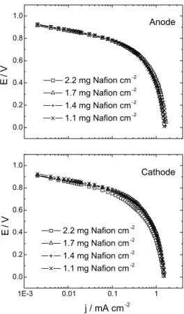
Effect of the Nafion content in the catalyst layer of the electrode
Figure 5 shows the effect of the Nafion loading on both electrodes on the fuel cell performance. It is seen that changes in the Nafion loading either in the anode or in the cathode do not appreciable change the fuel cell performance under low humidification conditions.
The active zone at the catalyst layer of a gas diffusion electrode is a three-phase region containing the polymer electrolyte, the gaseous reactant, and the Pt/C catalyst. The dispersed Pt/C catalyst forms agglomerate zones filled with the electrolyte and presenting a thin film of pure electrolyte covering the outside surface of these flooded zones. The agglomerates are intercalated by open channels, through which the reactant gas reaches the border of the
Figure 2. Cell potential-current density plots for H2/O2 1 atm for
PEFC with Nafion 117 membrane at different cell and humidifiers temperatures: (a) Nafion without impregnation; (b) Nafion impreg-nated with HPW. Electrodes with 20% Pt/C, 0.4 mg Pt cm-2, and 1.1
mg Nafion cm-2 in the catalyst layer and 15 % Teflon in the diffusion
layer. TC = cell temperature; Th = hydrogen and oxygen humidifiers
temperatures.
Figure 3. Cell potential-current density plots for H2/O2 1 atm for PEFC single cells at optimum operational conditions. The thickness of the Nafion membranes was changed as indicated. Electrodes with 20% Pt/C, 0.4 mg Pt cm-2, and 1.1 mg Nafion cm-2 in the catalyst
layer and 15 % Teflon in the diffusion layer. TC = cell temperature;
thin film, dissolves in the electrolyte and diffuses to the internal flooded zones where the reaction takes place. The Nafion loading affects the structure of this three-phase region causing changes in the electrode active area, in the overall ionic resistance, and on the mass transport phenomena in the gas and in the liquid phases.
The similarity of the results in Figure 5 seems to indicate that under low humidification conditions or high electrolyte resistivity, the expected rise in the electrode active area with the increase of Nafion loading is not confirmed. Also, the similarity of the polarization curves indicates that the changes of the Nafion loading in the electrode do not lead
to any significant effect in the membrane properties, implying an insignificant action on the retention of the water electrochemically generated in the cathode.
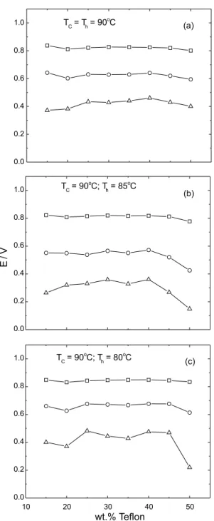
Effect of the Teflon content in the diffusion layer of the electrode
The cell potential vs. current density characteristics for the fuel cell with electrodes containing different Teflon contents in the diffusion layer presented similar trends as those observed in the study of the Nafion loading (Figure 5). These results are summarized in Figure 6 in terms of plots of the cell potential as a function of the Teflon content, for several current densities and humidification conditions. At low current densities, the cell performance does not present variations, showing that the amount of Teflon has a marginal effect on the active electrode area. A small effect of the Teflon content is observed at high current densities, noting that after 40 wt.% Teflon there is a decrease in the cell performance, particularly under low humidification conditions (Figures 6b and 6c).
Figure 4. Cell potential-current density plots for H2/O2 1 atm PEMFC single cells at several temperatures for the cell and humidifiers. The thickness of the Nafion membranes was changed as indicated. Elec-trodes with 20% Pt/C, 0.4 mg Pt cm-2, and 1.1 mg Nafion cm-2 in the
catalyst layer and 15 % Teflon in the diffusion layer. TC = cell
temperature; Th= hydrogen and oxygen humidifiers.
Figure 5. Cell potential-current density plots for H2/O2 1 atm PEFC
single cells at 90 oC for the cell and humidifiers. Electrodes with
20% Pt/C and 0.4 mg Pt cm-2 in the catalyst layer and 15 % Teflon in
It has been proposed that due to the hydrophobic properties, high Teflon contents may help to diminish the effect of the membrane drying through the retention of the water generated in the cathode side.33 This would be
verified through an increase of the cell performance with the increase of Teflon content, particularly at high current densities where the amount of water introduced by the
electrochemical reaction is higher. However, the results of the present investigation do not confirm this expectation. In fact, the results in Figure 6 at high current densities indicate a lowering of the cell performance for high Teflon contents, probably caused by a decrease of the membrane conductivity. This may be attributed to a less effective condensation of the water vapor contained in the reactant gases.
Conclusions
It is observed that when the PEFC is operated at temperatures equal or higher than those of the gas humidifiers there is an increase of the membrane resistance caused by a lowering in the water content. This effect is independent of the membrane thickness, although it is more apparent for thicker electrolyte films. Better performances are obtained for thinner membranes because the overall electrolyte resistance is smaller, independently of the humidification conditions.
The use of membranes impregnated with phosphotungstic acid leads to an increase of the overall membrane resistance, probably caused by the polymer degradation. In the presence of PWA, the physicochemical properties of the membrane do not appreciably change with temperature. However, a lower humidification temperature affects the electrode performance leading to a change in the Tafel slope due to the increased electrolyte resistivity inside the catalyst layer.
Changes on the Nafion loading in the gas diffuison electrode do not lead to any significant effect in the membrane properties, implying an insignificant action on the retention of the electrochemically-generated water in the cathode. Results at high current densities indicate a small lowering of the membrane conductivity for high Teflon contents in the diffusion layer of the electrode. This may be attributed to a less effective condensation of the water vapor contained in the reactant gases.
Acknowledgments
The authors thank Fundação de Amparo à Pesquisa do Estado de São Paulo (FAPESP) and Conselho Nacional de Desenvolvimento Científico e Tecnológico (CNPq) for financial support.
References
1. Gottesfeld, S.; Halpert, G.; Landgrebe, A. eds.; Proton
Con-ducting Fuel Cells, The Electrochemical Society: New Jersey,
1995.
Figure 6. Plots of the cell potential as a function of the Teflon
content in the electrodes diffusion layer, for different humidifica-tion condihumidifica-tions and at several current densities: (£) 0.03; () 0.4
and (H) 1.0 A cm-2. Electrodes with 20% Pt/C, 0.4 mg Pt cm-2, and
2. Paganin, V. A.; Ticianelli, E. A.; Gonzalez, E. R.; J. Appl.
Electrochem. 1996, 26, 297.
3. Paganin, V. A.; Oliveira, C. L. F.; Ticianelli, E. A.; Springer, T. E.; Gonzalez, E. R.; Electrochim. Acta 1998, 43, 3761. 4. Paganin, V. A.; Ticianelli, E. A.; Gonzalez, E. R.; J. Power
Sources 1998, 70, 55.
5. Wilkinson, D. P.; Voss H. H.; Prater, K.; J. Power Sources
1994, 49, 117.
6. Okada, T.; Xie, G.; Gorseth, O.; Kjelstrup, S.; Nakamura, N.; Arimura, T.; Electrochim. Acta 1998, 43, 3741.
7. Okada, T.; Xie, G.; Gorseth, O.; Meeg, M.; Electrochim. Acta
1998, 43, 2141.
8. Fuller, T. F.; Newman, J.; J. Electrochem. Soc. 1992, 139, 1332.
9. Bernardi, D. M.; Verbrugge, M. W.; J. Electrochem. Soc. 1992,
139, 2477.
10. Springer, T. E.; Zawodzinski, T. A.; Gottesfeld, S.; J.
Electrochem. Soc. 1991, 138, 2334.
11. Sena, D. R.; Ticianelli, E. A.; Paganin, V. A.; Gonzalez, E. R. ;
194th Meeting of The Electrochemical Society, Boston, MA,
EUA, 1998.
12. Verbrugge, M. W. And Hill, R. F.; J. Phys. Chem. 1988, 92, 6778.
13. Verbrugge, M. W. And Hill, R. F.; J. Electrochem Soc. 1990,
137, 886.
14. Springer, T. E.; Wilson, M. S.; Gottesfeld, S.; J. Electrochem.
Soc. 1993, 140, 3513.
15. Springer, T. E.; Zawodzinski, T. A.; Wilson, M. S; Gottesfeld, S.; J. Electrochem. Soc. 1996, 143, 587.
16. Eikerling, M.; Kharkats, Y. I.; Kornyshev, A. A.; Volfkovich, M.; J. Electrochem. Soc. 1998, 145, 2684.
17. Sena, D. R.; Ticianelli, E. A.; Paganin, V. A.; Gonzalez, E. R.;
J. Electroanal. Chem. 1999, 477, 164.
18. Buchi, F. N.; Srinivasan, S.; J. Electrochem. Soc. 1997, 144, 2767
19. Futerko, P.; Hsing, I-M.; Electrochim. Acta 2000, 45, 1741. 20. Wang, J. T.; Savinell, R. F.; Electrochim. Acta 1992, 37, 2737. 21. Nguyen, T. V.; White, R. E.; J. Electrochem. Soc. 1993, 140,
2178.
22. McNicol, B. D.; Rand, D. A.; Power Sources for Electric
Ve-hicles, Elsevier: Amsterdam, 1984.
23. Malhotra, S.; Datta, R.; J. Electrochem. Soc. 1997, 144, L23. 24. Paganin, V. A.; Freire, T. J. P.; Ticianelli, E. A.; Gonzalez, E.
R.; Rev. Sci. Instrum. 1997, 68, 3540.
25. Srinivasan, S.; Ticianelli, E. A.; Derouin, C. R.; Redondo, A.;
J. Power Sources 1988, 22, 359.
26. Rho Y. W.; Srinivasan, S.; J. Electrochem. Soc. 1994, 141, 2089.
27. Springer, T. E.; Zawodzinski, T.; Gottesfeld, S.; J. Electrochem.
Soc. 1991, 138, 2334.
28. Srinivasan, S.; Hurwitz, H. D.; Bockris, J. O’M.; J. Chem.
Phys. 1967, 46, 3108.
29. Srinivasan, S.; Hurwitz, H. D.; Electrochim. Acta 1967, 12, 495.
30. Burshtein, R. Kh.; Lainer, D. I.; Shumilova, Na. A.; Tarasevich, M. R.; Khruschcheva, E. I.; Gordon, A. A.; Levedeva; E. N.; Cherkashina, N. V.; Karonik, V. U.; Sov. Electrochem. 1972,
8, 115.
31. Giner, J.; Hunter, C.; J. Electrochem. Soc. 1969, 116, 1124. 32. Springer, T. E.; Raistrick, I. D.; J. Electrochem. Soc. 1989,
136, 1594.
33. Nakagawa, T.; Aoki, M.; Seya, A.; Komoshita, T.; Fuel Cell
Seminar Abst. 2000, 1, 391.
Received: January 18, 2002
Published on the web: July 16, 2002