246/ Vol. XXXIV, No. 3, July-September 2012 ABCM
Sabri Ozturk
[email protected] Abant Izzet Baysal University Department of Mechanical Engineering 14030 Bolu, Turkey
Erhan Altan
[email protected] Yıldız Technical University Department of Mechanical Engineering 34339 Istanbul, TurkeySlip-Line Metal Cutting Model with
Negative Rake Angle
A small dead region is seen in front of the rake face of the tool during cutting with negative rake. The lack of knowledge about the stagnant region in the cutting with negative rake requires researching new models. In this work, cutting mechanism of the metal cutting with negative rake angle tools and the stagnation zone formation were studied. A model was generated from the experimental work by usage of the Dewhurst and Collins’ matrix technique for solving the slip-line problem numerically. This model was applied at negative rake angles from 0° to -70°. All slip line angles in the slip line model that consist of three regions were resolved with the help of the experimental data. Variation of the dead metal zone and slip line regions with negative rake angle was determined. Effects of the negative rake angle on the cutting and thrust forces were investigated according to the cutting speed.
Keywords: stagnant region, cutting forces, slip-line, negative rake angle
Introduction1
In the metal cutting with negative rake cutting tools, the strength of the wedge increases, heat conduction from cutting edge to the tool shank improves, and the tool life increases in comparison with the positive rake cutting tools. Because of these properties, single point cutting tools with negative rake geometry are widely used. Also, in grinding process, the cutting mechanism of abrasive grid is similar to the cutting mechanism of single point cutting tools with negative rake angle. Moreover, in ultra-precision or micro machining, at depths of cut smaller than the tool edge radius, tool presents negative rake geometry. All these applications show the importance of understanding the cutting mechanism with negative rake cutting tools.
Several researchers have shown a significant effort in trying to understand the cutting mechanism in metal cutting with negative rake angle.Abdelmoneim et al. (1983) studied with orthogonal tools having negative rake angles to observe the effect of tool rake angle, cutting speed and depth of cut on the cutting forces. Furthermore, they realized that the force components and chip thickness decrease with increasing cutting speed. A slip-line solution, which was investigated by Abebe (1981), can be used to calculate the cutting forces required to cut a material and to estimate the friction conditions of metal cutting. To make the basic mechanism of metal removal clear, Kıta et al. (1975) considered metal cutting with abrasive single grid simulated conical tool. They observed the mechanism of the metal removal by the cutting tool with large negative rake angle and the behavior of the material ahead of the tool face during cutting. According to the authors, the dead-metal zone plays a crucial role in the chip formation. Komanduri (1971) defined that plastic deformation takes place ahead of the tool tip and into the machined surface at high negative rakes and small depths of cut. Kopalinsky and Oxley (1984) investigated the effect of rake angle on Ft (thrust force)/Fc (cutting
force) during cutting with negative rake angle. It was found that the force ratio Ft/Fc increased considerably with the increase in the
negative rake angle. The increase in Ft/Fc can only be accounted for
by the friction angle increasing as uncut chip thickness decreases. Abdelmoneim and Scrutton (1974) denoted that cutting forces rise as negative rake angle becomes more negative. Günay et al. (2004) studied the effects of cutting speed and negative rake angle on cutting forces. They concluded that cutting forces reduce as negative rake angle increases gradually from negative to positive.
The first model with a dead zone for metal cutting with negative rake angle tool was developed by Abebe (1981). Mathematical relationships of the model were also presented. Dundur and Das
Paper received 4 May 2011. Paper accepted 28 November 2011 Technical Editor: Alexandre Abrão
(2009) presented two slip-line field models for orthogonal machining with a worn tool with a finite flank wear land. Jin and Altintas (2010) offered a slip-line field model which considers the stress variation in the material deformation region due to the tool edge radius effect for micro-cutting process. A slip-line field based force modeling approach is also proposed to capture the worn tool cutting mechanism under the combined effects of both flank and crater wear in orthogonal cutting by Long and Yong (2010).A slip line model for machining with negative rake angles from 0° to −60° at constant cutting speeds was presented by Ozturk (2012).
J. of the Braz. Soc. of Mech. Sci. & Eng. Copyright 2012 by ABCM July-September 2012, Vol. XXXIV, No. 3 / 247
zone. In the models mentioned above, this metal-dead zone was considered stagnant. In contrast, alteration of this zone was observed by Kıta et al. (1975, 1978) in the experimental studies.
In the present study, a slip line model for metal cutting with negative rake angle tool was developed. Mathematical formulation of the model was established according to the Dewhurst and Collins’s matrix technique for numerically solving slip-line problems. All slip line angles in the slip line model that consist of three regions were resolved with the help of experimental data. Variation of the dead metal zone and slip line regions with negative rake angle was determined. Effect of the negative rake angle on the cutting and thrust forces was investigated according to the cutting speed.
Nomenclature
F = resultant force
Fc = cutting force
Ft = thrust force
k = material shear flow stress
PA = hydrostatic pressure at point A
P and Q = members of a set of basic matrix operators
t = uncut chip thickness
Vc = cutting speed
w = width of cut
Greek Symbols
σ1and σ2 = radii of curvature of two base slip-lines HN and ML
α1, α2 = angles of the vertices on each side of the intersection of the slip-line AK with the free surface of work material
α0 = reliefangle
θ1, θ2, θ3, θ4= slip-line angles
η = slip line angle of the HNM region
δ = slip line angle of the dead metal region
γ = rake angle
ρ = total velocity jump across the slip-lines
τ = shear stress
ω = angular velocity of a machined chip
The Slip Line Model
Models started in the 1960's were studied to simplify the models of metal cutting theoretically, up to present day. Albrecht (1960) based his model on the existence of a stagnation point on the radius where the work material’s tangential velocity vanished. Dewhurst (1978) proposed the slip-line model for metal cutting with a curled chip when using a flat-faced cutting tool. In this model the force acts between the chip and obstruction. Fang’s (2002) model took into account the tool–chip contact on the tool primary and secondary rake faces and at the chip-groove backwall. Fang and Dewhurst (2005) developed a model to fully take into consideration the built-up edge formation and chip-built-up curling effect. Nevertheless there is not a specific formulation obtained for metal cutting with negative rake angle tool in any of these models. In the present study, some basic assumptions have been made in the modeling. These include orthogonal machining assumption, which states that the work material is rigid, perfectly plastic. In other words, the material specifications do not change with strain, strain rate and temperature.
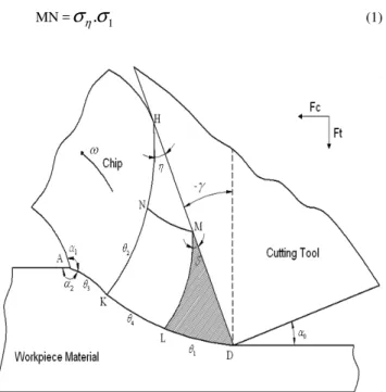
Regions in the developed model are given in Fig. 1:
• DLM, the dead region in front of the tool and next to the rake face of the tool.
• AK, the convex region that makes the chip curls.
• KLMN curvilinear quadrilateral region, the region providing contact between slip plane surface and HNM region.
• HNM region, which comes into existence as the deformed chip rubs with the rake face of tool.
Mathematical formulation of the model
The matrix algorithm developed by Dewhurst and Collins (1973) in order to solve slip line problems is used in this study. This algorithm is being applied to solve plain friction limited slip line problems. The hodograph for this slip-line model is seen in Fig. 2 (Ozturk, 2012).
P and Q are the basic matrix operators defined by Dewhurst and Collins (1971).
Two vectors defined for modeling purposes are HN and ML. They are σ1 and σ2 vectors respectively. Relationships among the
slip line model in Fig. 1 are expressed in Eqs. (1)-(6).
MN =
σ
η.
σ
1 (1)Figure 1. The slip line model for metal cutting with negative rake angle tool.
Figure 2. Hodograph for the slip line model.
DL =
σ
δ.
σ
2 (2) KL = MN +ρ
.
c
(3) KL =
.
.
22
2 θη
σ
ηθ
MN
Q
P
−
(4)MN =
P
.
KL
Q
.
KN
4 2 24θ θθ
KN =
P
θ3η.
σ
2−
Q
ηθ3.
MN
(6)
σ2 is found in terms of σ1 by solving the equations above. This way,
the number of vectors decreases to one.
Equations obtained from the hodograph in Fig. 2 are given in Eqs. (7)-(13).
=
hn
ω
.
σ
1 (7)KN
n
k
′
=
ω
.
(8)c
l
k
′
′
=
ρ
.
(9)mn
hn
=
σ
η.
(10)n
k
Q
l
k
P
mn
=
.
′
′
−
.
′
2
2 θη
ηθ (11)
KN
Q
c
P
mn
.
.
.
.
2 2
ρ
θηω
ηθ
−
=
(12)KN
Q
c
P
.
.
2 2 1 . η θ η ηθσ
σ
ρ
ω
+
=
(13)When the forces transmitted across the slip lines DL, KL, and AK are denoted by vectors FSK, FKL, and FDL, then the resulting
cutting force F can be written as given Eq. (14). Slip line AK is determined as expressed in Eq. (15). Friction angle between tool and chip is given in Eq. (16).
ktw
F
ktw
F
ktw
F
ktw
F
=
AK+
KL+
DL(14)
AK=
.
c
ω
ρ
(15)
=
−k
τ
δ
1cos
(16)PA/k and τ/k values have to be determined in order to make this
slip line model complete. PA, k, and τ denote hydrostatic pressure,
material shear flow stress and tool-chip frictional shear stress, respectively. Fang and Jawahir (2002) had specified change of PA/k
and τ/k according to the negative rake angle and presented this as a table in their study for medium carbon steel. In this study, accepted values for the slip line model with a brass material are given in Table 1. Table 2 is used for the value of PA/k.
Table 1. δ and ττττ/k values considering negative rake angle.
γ 0° -10° -20° -30° -40° -50° -60° -70°
k
τ
1 0.95 0.9 0.85 0.80 0.75 0.70 0.65δ 0 9º 13º 16° 18° 20° 21° 25°
Table 2. PA/k value considering negative rake angle.
γ
0° -10° -20° -30° -40° -50° -60° -70°k
P
A 0.85 0.9 0.95 1 1 1 1 1Eventually τ/k value decreases and PA/k value increases as γ
becomes more negative. α1 is determined from the hodograph
δ
γ
θ
θ
θ
π
α
1=
+
3−
1−
4−
−
(17)Experimental Study
Cutting is performed under definite metal cutting conditions, in order to apply the slip line model of metal cutting with negative rake angle and to determine the effect of negative rake angle on the dead region, the cutting and thrust forces. Slip line angles based on slip line model were attained from experimentally gathered data.
Figure 3. Quick stop device.
Experimental equipment
J. of the Braz. Soc. of Mech. Sci. & Eng. Copyright 2012 by ABCM July-September 2012, Vol. XXXIV, No. 3 / 249
Workpiece materials and cutting tools
Brass workpiece material was used in this study, since it was stated that dead region existed and built up edge did not come into being at metal cutting with brass (Kopalinsky and Oxley, 1984). The experimental samples were made of CuZn30. Chemical composition of the samples was as follows: Cu% = 69.809; Zn% = 30.138; Sn% = 0.0029; Pb% = 0.005; Fe% = 0.0219; P% = 0.0019. The dimensions of the supplied workpiece material were 32 mm x 30 mm x 1.5 mm.
A TPGN 160308 insert which has no cutting edge radius was used during the experiments with negative rake angle tool. The insert was fastened on the tool shank by mechanical compression. Length of the tool was designed in accordance with the strain gages. Shim, clamp, clamping screw, and lock pin were used to mount the insert. Relief angle of cutting tool was 11 degrees.
Cutting parameters
Metal cutting operation wasperformed at eight different rake angles, three various cutting speeds and cutting depth for the experimental work done about the cutting operation driven with negative rake angle tool. Metal cutting parameters used in the experiments are given in Table 3. Experiments were replicated two times, and average values used in the experiment results. The standard error value of the experiment was 0.021 which is quite reasonable.
Calibration was done in order to measure thrust and cutting forces accurately. To derive Ft and Fc forces, microstrain values
were read from the strain gages bonded on the right, front and rear sides of the shank and these values were converted to force values within the calibration measurements.
Table 3. Cutting parameters used in the experiments.
Experiment group No.
Cutting speed Vc (m/min)
Uncut chip thickness t(µm)
Rake angle
γ (º) 1 0.25, 0.5, 0.75 50, 100, 150 0 2 0.25, 0.5, 0.75 50, 100, 150 -10 3 0.5 50, 100, 150 -20 4 0.25, 0.5, 0.75 50, 100, 150 -30 5 0.5 50, 100, 150 -40 6 0.25, 0.5, 0.75 50, 100, 150 -50 7 0.5 50, 100, 150 -60 8 0.5 50, 100, 150 -70
Results and Discussion
Cutting and thrust forces
As a result of the experiments, variation of Ft and Fc values
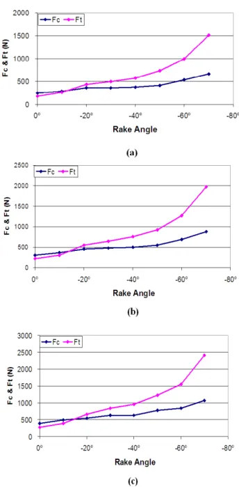
according to uncut chip thickness cutting depth at constant cutting speed and variable negative rake angle is illustrated in Figs. 4-6. Figure 4 shows thrust and cutting forces versus rake angles. Fc
values are given in Fig. 5, versus rake angle for different rake angles. Thrust force variation with rake angle is shown in Fig. 6.
The results stated below are derived from the graphics:
• In Fig. 4(a-c) it appears that cutting and thrust forces rise by growing negative rake angle.
• Cutting force increases as the cutting depth increases at the constant cutting speed. Cutting force increases relatively faster if the rake angle is -50º or less (Fig. 5(a-c)).
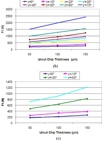
• Thrust forces increase with increasing uncut chip thickness at constant cutting speeds as shown in Fig. 6(a-c).
• If the negative rake angle is more negative than -10º, it is obvious from these graphics that the increase ratio of the
thrust force is greater than the increase ratio of the cutting force (Fig. 4(a-c)).
Cutting and thrust forces decrease parallel to increasing cutting speed. The reason for decreasing forces may be explained with the rise of temperature, great amount of chip formed in unit time and shortened contact length. Along with the enlarged plastic deformation zone, angle of the vertices on side of the intersection of the slip-line AK with the free surface of work material diminished and the forces increased as the rake angle became more negative. The effect of rake angle on cutting forces, especially on thrust forces, became more noticeable when the negative rake angle increased.
Figure 4. Thrust (Ft) and cutting forces (Fc)variation with rake angle (Vc =
Figure 5. Fc variation with uncut chip thickness for rake angle tools, a) Vc =
0.25 m/min, b) Vc = 0.50 m/min and c) Vc = 0.75 m/min.
Figure 6. Ft variation with uncut chip thickness for rake angle tools, a) Vc =
0.25 m/min, b) Vc = 0.50 m/min and c) Vc = 0.75 m/min.
In the scope of this study, change of cutting and thrust forces according to cutting speed were investigated and the modeling has been done by using instantaneous stop device for various speeds, at a wide range of rake angle between 0° and −70°, for CuZn30 workpiece material.
Slip line angles
Slip line angles based on the model may be found by the determination of cutting and thrust forces. Based on Hill’s theory (1954), for every particular value of the tool rake angle, the extension of the stress field into the assumed rigid zones is only possible over a limited range of solutions to the slip line model. If an accepted solution is taken into consideration, metal cutting may eventuate for the specific values of α1 and α2 cited in Fig. 1, for every single surface
between AK slip line and free surface. Thus, the conditions expressed in the following equations have to be constituted.
1
2
3
2
2
1
2
−
−
1≤
≤
1−
+
π
α
α
π
k
P
A(18)
− + ≤ ≤ −
−
4 2 1 1
4 cos .
2 2 2
π
α
π
α
k PA
(19)
Slip line angles (θ1, θ2,θ3, θ4, η, α1),confirming Eqs. (18) and
J. of the Braz. Soc. of Mech. Sci. & Eng. Copyright 2012 by ABCM July-September 2012, Vol. XXXIV, No. 3 / 251
instantaneous stop device with the F/k.t.w value calculated by Math Cad by means of rake angle, slip line angles, shear strain and hydrostatic pressure variables defined by the user. Accuracy of the variables depends on the satisfaction of the equations (18) and (19).
Figures 7(a)-(c) and 8(a)-(b) represent the variation of slip line angles of the existing model with negative rake angle values.
Figure 7. Relation between slip line angles of the existing model and negative rake angles, a) k.t.w = 12.45, b) k.t.w = 24.9 and c) k.t.w = 37.35.
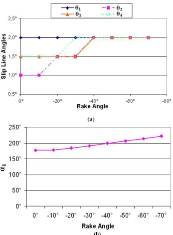
Figure 8. Slip line angles variation with negative rake angles, a) θ1, θ2, θ3,
θ4 and b) α1.
It can be seen that as negative rake angle increases, dead metal region slip line angle (δ) increases and HNM region slip line angle (η) decreases (Fig. 7(a)-(c)). Slip line angles θ2 and θ4 increased for
negative rake angle values greater than −20° as θ1 stayed constant.
Nonetheless, slip line angle θ3 increased for negative rake angle
greater than −30°, as seen in Fig. 8(a). Area of the dead region MLD enlarged as negative rake angle became more negative. The reason for the increase in the angle between vertices on each side of the intersection of the slip-line and free surface (α1) may be explained
with the enlargement of plastic deformation zone as rake angle increased (Fig. 8(b)).
Conclusion
In this study, a model for metal cutting with negative rake angle tool was developed. Dead region was considered in this model. A detailed experimental investigation was presented for the effects of negative rake angle on the thrust and cutting forces. Variation of the cutting and the thrust forces with cutting speed were determined by using instantaneous stop device for various speeds, at a wide range of rake angle between 0° and −70°, for CuZn30 workpiece material. It was concluded that cutting and thrust forces increased parallel to the increasing negative rake angle and uncut chip thickness, whereas they decreased with the increasing cutting speed.
Significant results acquired in this study are given below:
• The slip line field model was divided into three sub-regions. Mathematical formulation of the model was done based on basic matrix algorithm of Dewhurst and Collins (1973).
up to -70°. Negative rake angle and cutting speed were found to be affecting force components. Ft/Fc ratio increased
as negative rake angle became more negative.
• The unknown slip-line angle pair was solved depending on the force data obtained experimentally and variation of the sub-regions with negative rake angle was determined. Changes of MLD dead metal zone and HNM region were analyzed. It was revealed that dead zone enlarged as negative rake angle became more negative.
• Owing to the fact that the model involved many mathematical relationships, Math Cad software was used to obtain the solution. Analysis of all the slip-line field regions may be done by changing the values of the variables on the Math Cad program. This is important in terms of the solution convenience of the model.
• The angle α1 increased with increasing negative rake
angle’s absolute value, because of expanding plastic deformation zone.
Acknowledgements
The authors would like to thank Yıldız Technical University Scientific Research Projects Coordination Department for financial supports by research grant No 25-06-01-02.
References
Abdelmoneim, M.Es., Nasser, A.A., Abdel Mahboud, A.M., 1983, “A fundamental study of cutting employing orthogonal negative rake tools”, Wear, Vol. 85, pp. 171-180.
Abdelmoneim, M.Es., Scrutton, R.F., 1974, “Tool edge roudness and stable build-up formation in finish machining”, Journal of Engineering for Industry, pp. 1258-1267.
Abebe, M., 1981, “A slip-line solution for negative rake angle cutting”,
Manufacturing Engineering Transactions, Vol. 9, pp. 341-348.
Albrecht, P., 1960, “New development in the theory of the metal-cutting process part 1: the ploughing process in metal cutting”, Journal of Engineering for Industry, pp. 348-358.
Dewhurst, P., Collins, I.F., 1973, “A matrix technique constructing slip-line field solutions to a class of plane strain plasticity problems”, Int. J.
Numer. Methods Eng., Vol. 7, pp. 357-378.
Dewhurst, P., 1978, “On the non-uniqueness of the machining process”,
Proc. R. Soc. London Ser. Vol. 360, pp. 587-610.
Dundur, S.T., Das, N.S., 2009, “Slip line field modeling of orthogonal machining for a worn tool with elastic effects and adhesion friction at the contact regions”, Journal of Materials Processing Technology, Vol. 209, pp. 18-25.
Fang, N., Dewhurst, P., 2005, “Slip-line modeling of built-up edge formation in machining”, International Journal of Mechanical Sciences, Vol. 47, pp. 1079-1098.
Fang, N., 2005, “Tool-chip friction in machining with a large negative rake angle tool” Wear, Vol. 258, pp. 890-897.
Fang, N., Jawahir, I.S., 2002, “Analytic predictions and experimental validation of cutting force ratio, chip thickness and chip black-flow angle in restricted contact machining using the universal slip-line model”, International Journal of Machine Tools & Manufacture, Vol. 42, pp. 681-694.
Fang, N., 2002, “Machining with the tool-chip contact on the tool secondary rake face-part 1: a new slip-line model”, International Journal of
Mechanical Sciences, Vol. 44, pp. 2337-2354.
Günay, M., Aslan, G., Korkut, İ., Şeker, U., 2004, “Investigation of the effect of rake angle on main cutting force”, International Journal of Machine Tools & Manufacture, Vol. 44, pp. 953-959.
Hill, R., 1954, “On the limits set by plastic yielding to the intensity of singularities of stress”, Journal of the Mechanics and Physics of Solids, Vol. 2, pp. 278-285.
Jin, X., Altintas, Y., 2011, “Slip-line field model of micro-cutting process with round tool edge effect”, Journal of Materials Processing Technology, Vol. 211, Issue 3, pp. 339-355.
Kıta, Y., Hata, S., Ido, M., 1975, “Investigation on the mechanism of metal removal”, Bull. Japan of Prec. Eng., Vol. 9, pp. 113-114.
Kıta, Y., Ido, M., Kawasaki, N., 1982, “A study of metal flow ahead of tool face with large negative rake angle”, Journal of Engineering for Industry, Vol. 104, pp. 319-325.
Kıta, Y., Ido, M., Hata, S., 1978, “The mechanism of metal removal by an abrasive tool” Wear, Vol. 47, pp. 185-193.
Kıta, Y., Ido, M., Tujı, Y., 1981, “The influence of the cutting speed on the mechanism of metal removal by an abrasive tool”, Wear, Vol. 71, pp. 55-63.
Komanduri, R., 1971, “Some aspects of machining with negative rake tools simulating grinding”, Int. J. Mach. Tool Des. Res., Vol. 11, pp. 223-233.
Kopalinsky, E.M., Oxley, P.L.B., 1984, “An investigation of feed and rake angle on the ratio of feed force to cutting force when machining with negative rake angle tools”, CIRP Annals - Manufacturing Technology, Vol. 33, pp. 43-46.
Lee, E.H., Shaffer, B.W., 1951, “The theory of plasticity applied to a problem of machining”, Trans. ASME, Vol. 73, pp. 405-413.
Long, Y., Huang, Y. 2010, “Combined effects of flank and crater wear on cutting force modeling in orthogonal machining, Part I: Model Development”, Machining Science and Technology, Vol. 14(1), pp. 106-128. Makino, R., Usui, E., 1973, “An analysis of stress and strain distributions in the plastic region of slow speed, steady-state machining”, Bull. Japan of Prec. Engg, Vol. 7, pp. 43-50.
Ozturk, S., 2012, “Slip-Line modeling of machining and determine the influence of rake angle on the cutting force”, Transactions of the Canadian
Society for Mechanical Engineering, Vol. 36, No. 1, pp. 23-35.
Palmer, W.B., Yeo, R.C., 1963, “Metal flow near the tool point during orthogonal cutting with a blunt tool”, Proceedings of the 4th International
MTDR Conference Oxford, pp. 61-71.