Optimal Selection of Tools for Rough Machining
of Sculptured Surfaces
Polychronis Spanoudakis, Nikos Tsourveloudis, Ioannis Nikolos
Abstract— As the needs for fast, efficient and high quality production increases, it is important for every company or manufacturing facility to be able to optimize the resources needed. This paper focuses and resolves the problem of best tool selection for a rough milling operation on 3-axis machines, especially for the production of sculptured surfaces. The tool selection methodology is based on a genetic algorithm optimization procedure. The objective of the algorithm is to achieve quicker machining parameters. Direct comparisons between CAM software simulations and real time experiments have been performed to verify the results. Tool type comparison between flat and ball end cutters is also conducted.
Index Terms— tool selection, milling, sculptured.
I. INTRODUCTION
The CNC machining optimization is a widely researched topic with many publications regarding several aspects of the operation on milling machines. Some of the topics addressed are: a) Production and quality optimization [1, 2, 3, 13], b) Simulation and verification model development [4, 5, 6], c) Tool path feedrate optimization [8, 9, 10] and others. In the other hand, a high number of CAM software are developed the last years and their efficiency and accuracy increases rapidly in order to meet customer expectations. The direct connection of CAM and CAD software provides the technology needed in order to optimize productivity times. Since machining centers on production lines are operated based on such software, it is important to work on this topic in order to provide tools and solutions that simplify the decisions of machining parameters.
Optimal tool selection is already studied in some aspects. Mostly, the end user of CAM software uses a trial-and-error method or personal experience to select tools. For example freedom of interference as a criterion by which to select tools automatically was proposed [18]. However, an interference-free tool may be feasible, but not optimal. In
cases of pockets, a set of tools are proposed, with the last corresponding to a diameter equal to the smallest passage width that the tool must pass through [16]. In any case, tool selection does not include just the diameter but also the type of tool. Also, the tool path is not the only aspect that should be optimized, since machining time is also affected by more important machining parameters.
Manuscript received December 30, 2007. This work has been partially funded by the General Secretariat of Research and Technology of Greece – Pythagoras II grant.
P. Spanoudakis is with the Technical University of Crete, Department of Production Engineering and Management, Chania, Crete, 73100 GREECE. (corresponding author phone: +302821037427; fax: +302821069410; e-mail: [email protected]).
N. Tsourveloudis is with the Technical University of Crete, Department of Production Engineering and Management, Chania, Crete, 73100 GREECE. (e-mail: [email protected]).
I. Nikolos is with the Technical University of Crete, Department of Production Engineering and Management, Chania, Crete, 73100 GREECE. (e-mail: [email protected]).
Rough machining is recognized as the most important procedure influencing the machining efficiency and is critical for the success of the following finishing process [17]. Thus, the optimization of this process can result in shorter total machining times as also in better or predefined final surface finish. In order to take control of these features tool selection is a critical decision, concerning the type of tool used and its diameter. At the same time, the main machining parameters (depth of cut, feed rate and cutting speed) do affect a process and every optimization effort. But, even though feed rate and cutting speed are recognized to have great effect they can be chosen according to tool manufacturer recommendations given in catalogues [12]. Especially, since they are affecting all types of tools on a same manner it is not important to consider their influence in the experimentation that follows.
The scope of this paper is to present optimal selection of tools for rough machining of sculptured surfaces through genetic algorithm optimization. For this purpose, tools of different type and diameter are checked and the best is selected. Machining parameters such depth of cut and stepover are also considered and their influence is discussed. Simulation and real experiments are compared in order to check the validity of results produced by the CAM software used. Useful insights arise by the results obtained and the algorithm developed to maximize cutting efficiency and reduce machining time.
II. ROUGHING PROCESS
Generally, rough machining is the first stage of material removal process during which it is desired to remove most of the stock material volume, approximating the final product surface. Finish milling aims to the final form of the product according to surface quality specifications. Thus, the roughing process is the step that can define the total time of machining as also affect the final form.
A. Parameter Selection
of Experiments in order to find the most influencing parameters on roughing process [11]. This work indicated that depth of cut and stepover are two of the most affecting parameters on the process:
• Depth of cut is the distance of two neighboring passes in Z-axis.
• Stepover defines the distance between two consecutive passes on the XY plane.
Considering the suggestions made in [11], the following parameters are selected in this work towards the optimization of the roughing process: 1)Tool type, 2)Tool diameter, 3)Depth of cut, 4)Stepover.
Generally, selecting tool type and diameter is based on the material to be machined. In our case, an Aluminum 6063 series alloy is used through all tests and experiments and this defines directly a certain range of tools that are appropriate. So, from catalogues eight (8) tools ranging from 10-20mm are selected as the test database from which the optimal should be chosen. Specifically, four flat end mills are compared to equal ball end mills of the same diameters.
As already stated, even though feed rate and cutting speed do affect machining process are taken as constant values according to tool manufacturer recommendations.
B. Results quality criteria
Quality criteria of the roughing process are the least machining time and the least remaining volume after roughing. Machining time is the total time needed for the machining process. Remaining volume is the volume of part calculated after the machining process.
For the definition of machining processes, the tool path generation and results extraction the CATIA V5R15 software is used. In order to record the results mentioned above, a Visual Basic program which works together with CATIA in batch mode was developed and used.
III. EXPERIMENTAL SET-UP
In order to provide adequate results and recommendations, several experiments were decided to be performed before the optimization procedure. Those are:
Experiment 1. Exact effect of selected machining parameters on machining time and remaining volume.
Experiment 2. CAM software simulation results verification via comparison to real time rough process experiments.
A. Effect of Selected Machining Parameters
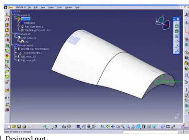
The first set of experiments involves verification of the influence of selected machining parameters (depth of cut and stepover) on roughing process. For this reason the designed part of Fig. 1 is used as the sculptured surface to be produced. The starting stock part is a 300x121x103 (LxWxH) aluminum solid bar. A flat end tool of 12mm diameter is used on several simulations where depth of cut and stepover are
altered. Machining time and remaining volume are recorded in every simulation. The results are summarized in Table 1 and diagrammatically presented in Fig. 2 and Fig. 3.
Fig.1. Designed part.
TABLE1.PARAMETER EFFECT ON ROUGHING PROCESS
Depth of Cut (mm)
Stepover (mm)
Roughing Time (sec)
Remaining Volume (mm3)
3 5 14331,03 1364090
4 5 10805,35 2461034
5 5 8647,39 2727517
3 6 12414,76 1369355
4 6 9399,76 2432252
5 6 7472,33 2735948
3 7 11688,75 1454511
4 7 8797,87 2436671
5 7 7008,59 2741276
0 2000 4000 6000 8000 10000 12000 14000 16000
3 4 5 6
Depth of Cut (mm)
Tim
e
(
s
e
c
) Stepover 5mm
Stepover 6mm Stepover 7mm
Fig.2. Depth of cut and stepover effect on machining time.
0 500000 1000000 1500000 2000000 2500000 3000000
3 4 5 6
Depth of Cut (m m )
V
o
lu
me
(mm3
)
Stepover 5mm Stepover 6mm Stepover 7mm
Fig.3. Depth of cut and stepover effect on remaining volume of machined part.
volume differences are observed. Since at rough process the least time should be achieved, both parameters should be included in the optimization algorithm.
B. CAM Software Results Verification
In order to validate the results obtained during simulation test runs using CATIA, a set of experiments are conducted on a HAAS VF2 CNC milling machine of the Machine Tools Laboratory of the Technical University of Crete, Greece. For the experiments a stock part of an Aluminum bar with dimensions 130x30x30mm (LxWxH) is used. The volume and weight of the bar are calculated and found: Weight: 246gr, Volume: 117000mm3. Thus the exact density is: d=2737.78 Kg/m3.
The stock and design part to be produced are shown in Fig. 4. Using CATIA, two different rough machining programs are produced. One with specific depth of cut (1mm), stepover (3mm) and flat end mill of 10mm diameter and the other with a ball end mill of 10mm diameter. The machining time is recorder and the weight of the final rough machined part is measured on a precision balance. Feed rate and spindle speed are constant on both experiments with values f=250mm/min and Vc=1600Rpm according to tool manufacturer
recommendations.
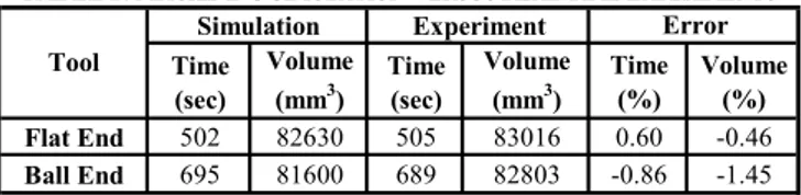
According to results presented on Table 2, simulations are confirmed by the experiments conducted. The percentage of error is low for both time and remaining volume and correspond to: Flat end mill: 1)time error is: 0.60% and volume error: 0.46%, Ball end mill: 1)time error=0.86% and volume error= 1.45%. Pictures of parts after roughing real time experiments are presented in Fig. 5.
The agreement of results first of all shows that CAM programs can provide a really good approximation of real machining experiments. Also, that the results of simulations obtained for flat or ball end tools are valid and can be trusted as inputs in the genetic algorithm optimization which follows.
Fig 4. Stock and final product design.
TABLE2.MACHINING SIMULATION VERSUS REAL TIME EXPERIMENTS
Time (sec)
Volume
(mm3)
Time (sec)
Volume
(mm3)
Time (%)
Volume (%)
Flat End 502 82630 505 83016 0.60 -0.46
Ball End 695 81600 689 82803 -0.86 -1.45
Simulation Experiment Error
Tool
IV. GENETIC ALGORITHM OPTIMIZATION PROCESS
As the main target is to achieve best tool and parameters
selection for the roughing process, optimization is conducted using a differential evolution genetic algorithm approach. The genetic algorithm is developed in-house and works in batch mode with direct communication with the CAM software (CATIA).
Differential Evolution algorithms represent a type of Evolutionary Strategy, especially formed in such a way, so that they can effectively deal with continuous optimization problems, often encountered in engineering design, and they are a recent development in the field of optimization algorithms [14], [15]. The classical DE algorithm evolves a fixed size population, which is randomly initialized. After the population initialization, an iterative process is started and at each iteration (generation), a new population is produced until a stopping condition is satisfied. At each generation, each element of the population can be replaced with a new generated one. The new element is a linear combination between a randomly selected element and a difference between two other randomly selected elements.
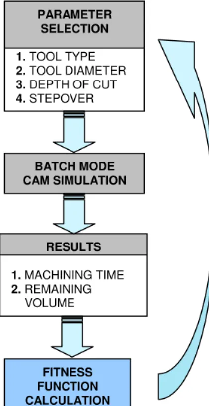
The optimization process proposed follows the steps of Fig. 6. First of all an initial chromosome is created with random parameter selection (tool type, tool diameter, depth of cut and stepover) which are also the parameters to be optimized. A batch mode simulation is then followed using CATIA in order to extract the required results for evaluation of the specific process. The results calculated are, as mentioned previously, machining time and remaining volume. According to result values a fitness function is used for evaluation:
Fitness Function: FF = α*Τ + β*V Where: T = machining time
V = Remaining volume α, β = weighting coefficients
The weighting coefficients are used in order to normalize the measuring units of time (seconds) and volume (cubic millimeters) and also to specify the most important parameter. At the roughing process the most important factor is to lower the time and so the coefficients used are α=0.7/1000 and β=0.3/100000. The target is to minimize the fitness function by changing the machining parameters.
a
b
Fig 5. Rough machining real time experiments with a)flat end tool, b)ball end tool.
provided to the genetic algorithm. Specifically, depth of cut ranges from 0.5 to 2mm with a step of 0.5mm and stepover ranges from 2 to 6mm with a step of 1mm. Using these constraints every new chromosome set by the algorithm is inside the set limits.
Two different cases of experiments are conducted and evaluated. The first considers just roughing optimization where the optimum parameters are chosen by the genetic algorithm while at the second two processes are considered, roughing and finishing. The later case targets on finding out if there is any difference on tool selection and the optimum tough machining values when series of processes are considered. This aspect is important, since until now most of the optimization algorithms proposed in bibliography take in account just one process.
A. One Process (Roughing) Optimization
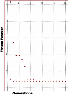
The optimization of the roughing process targets to the best choice of the parameters in order to achieve the lower machining time. As mentioned, the weighting coefficients used are α=0.7, β=0.3 and the constraints remain as set before. The genetic algorithm needs just ten generations with population equal to ten, in order to calculate the minimum fitness function FF=0.148 (Fig. 7). The parameters which correspond to this fitness value are: 1)Tool type=flat end mill, 2)Tool Diameter=20mm, Depth of cut=2mm and Stepover=4mm.
These results indicate that a flat end tool of the biggest diameter should be used and it is reasonable since the machining time is the most important criterion for this process. Depth of cut also is the highest that can be used presenting that even though as depth of cut increases so does the remaining volume, its influence on time is higher, resulting at this value. The optimum value for the stepover does arise a question on whether it should be higher since, as presented, time decreases as stepover increase.
Fig 6. Steps of the optimization algorithm.
It could be stated that this result just shows there is a combination of parameters which both influence time, the one with the biggest effect is set to maximum while the other stays lower in order to achieve the minimum fitness function. Nevertheless, after careful observation of the simulation paths produced by CATIA, it was validated that when a cutter of large diameter is used, compared to the machined part, the tool path remains unchanged even though stepover increases. More exactly, it was found that with a cutter of 20mm the machining time remained the same even though stepover increased from 2mm to 6mm. That means that the tool paths generated by the software do not change because of: a)large tool diameter and b)the constraint of minimum remained material thickness on the part. This constraint is used in order to avoid excess of material being removed during roughing process and at the same time in order to set the thickness that the finishing tool must remove.
B. Series of Processes (Roughing and Finishing) Optimization
Even though roughing results are clear about the parameter selection, the question that could be asked is: Are these results truthful since series of processes are always required to machine a part? In order to answer and at the same time validate our results, a new run of the genetic algorithm is done. This time the parameters evaluated are seven (7), including the best selection of tool type, diameter and stepover for the finishing process. The same database of tools used for roughing and the same constraints are applied. The fitness function is changed to:
FF2 = α*(Τ1+T2) + β*V Where: T1 = Rough machining time T2 = Finish machining time
V = Remaining volume of finished part α, β= weighting coefficients
The weighting coefficients used must target best surface finish of the machined part and so are set to: α=0.3/1000, β =0.7/10000.
BATCH MODE CAM SIMULATION
FITNESS FUNCTION CALCULATION
PARAMETER SELECTION
1. TOOL TYPE
2. TOOL DIAMETER
3. DEPTH OF CUT
4. STEPOVER
RESULTS
1. MACHINING TIME
2. REMAINING VOLUME
Using the genetic algorithm for 35 generations with population equal to fifteen, the minimum fitness function calculated found FF=0.165 (Fig. 8). A lower FF value –compared to rough optimization- is achieved, since the remaining volume on the part is considerably lower than in the roughing operation. The parameters which correspond to this fitness value are: 1) Roughing tool type=flat end mill, 2) Roughing tool Diameter=20mm, 3) Finishing tool type=ball end mill, 2) Finishing tool diameter=12mm, 5) Depth of cut=2mm and 6) Rough stepover=5mm, 7) Finish stepover=2mm.
The first observation on the results is that they confirm that the best tool for the roughing process is a flat end cutter of 20mm diameter as already appeared at the one process experiment.
More test runs of the algorithm revealed that change of the coefficients alters substantially the FF value and its corresponding parameters. In order to be sure whether series of processes should be considered for an adequate optimization of rough machining, more parameters must be used. Such are: a) thickness of material that is left on part from roughing and b) tool wear of the finishing tool.
The only parameter that is not affected is tool type and diameter, thus it can be chosen without considering the following processes.
Fig 7. Genetic algorithm generations versus fitness function values for roughing process.
Fig 8. Genetic algorithm generations versus fitness function values for roughing and finishing processes.
V. CONCLUSION
This paper is focused in the development of an optimization algorithm for best tool selection of rough machining on sculptured surfaces. The optimization is achieved using a differential evolution genetic algorithm. The results discussed include:
Evaluation of the effect of depth of cut and stepover, as major machining parameters and their influence on machining time and remaining volume. Multiple experimental results showed that stepover does not influence remaining material volume on a roughing operation. Feed rate and cutting speed are not taken in account, since the main objective is to choose the correct tool for this operation. That means that those factors for sure effect machining time and surface finish, but this influence would be observed on every tool choice. Also, tool manufacturers do provide good recommendations for the values of those parameters so it is easier to select an optimum feed rate or cutting speed from a catalogue.
Real time experiments showed that simulation results are really close to reality and thus CAM software is an adequate tool for optimization purposes.
Direct comparison of flat end cutters versus ball end cutters is conducted through simulation and genetic algorithm runs, firstly for just a rough machining process and secondly for a rough and finish machining process. The results indicate that for roughing the best tool choice is the biggest available in diameter (20mm), flat end tool. This is validated in both cases of simulations, so just flat end mills should be used.
These simulations also provide another important aspect, which is that rough machining parameter optimization should not be applied to one process without considering the next to follow. When just one process is optimized the results are not for sure the true optimum values. Especially when more parameters are used –feed rate, cutting speed- this is expected to affect more the final optimal parameter choice.
The only parameter that is not affected is tool type and diameter, which can be chosen without considering the following processes. That means the presented algorithm could be used for quick computation of the selection of the best tool for a roughing process with adequate results, which was the basic scope of this paper.
Future work includes expansion of the genetic algorithm for a complete optimization of machining parameters and tool selection for a series of processes.
ACKNOWLEDGMENT
This work has been partially funded by the General Secretariat of Research and Technology of Greece – Pythagoras II grant.
REFERENCES
[1] M. Alauddin, M.A.E. Baradie, M.S.J. Hashmi, “Computer-aided analysis of a surface-roughness model for end milling”, Journal of Materials Processing Technology (55), 1995, pp.123-127.
[3] F. Cus, J. Balic, “Optimization of cutting process by GA approach”,
Robotics and Computer Integrated Manufacturing Vol.19, 2003, pp.113–121.
[4] J. A. Crossman, D. H. Yoon, “A Cutter Motion Simulation System”, Journal of Integrated Design and Process Science, Vol. 4, No. 1, 26, 2000.
[5] R.B. Jerard, J.M. Angleton, R.L. Drysdale and P.Su, “The Use of Surface Points Sets for Generation, Simulation, Verification and Automatic Correction of NC Machining Programs”, Proceedings of NSF Design and Manufacturing Systems Conference, Society of Manufacturing Engineers, 1990, pp 143 -148.
[6] R.B. Jerard, S.Z. Hussaini, R.L. Drysdale, B.Schaudt, “Approximate methods for simulation and verification of numerically controlled machining programs”, The Visual Computer, Springer-Verlag, Vol. 5, 1989, pp.329-348.
[7] R. B. Jerard, R. L. Drysdale, K. Hauck, B. Schaudt, J. Magewick Ford, “Methods for Detecting Errors in Numerically Controlled Machining of Sculptured Surfaces”, IEEE Computer Graphics & Applications,1989.
[8] Β. Choi, R. Jerard, Sculptured Surface Machining - Theory and
Applications, Kluwer Academic Publishers, 1998.
[9] R. B. Jerard, B. K. Fussell, J. G. Hemmett, M. T. Ercan, “Toolpath Feedrate Optimization: A Case Study”, Proceedings of the 2000 NSF Design & Manufacturing Research Conference, 2000.
[10] R. B. Jerard, B. K. Fussell, M. T. Ercan, “On-Line Optimization of Cutting Conditions for NC Machining”, 2001 NSF Design, Manufacturing & Industrial Innovation Research Conference, 2001. [11] A. Krimpenis, A. Fousekis, G. Vosniakos, “Assessment of sculptured
surface milling strategies using design of experiments”, International Journal of Advanced Manufacturing Technology, pp. 1–10, 2004.
[12] Seco Selection 2004, Seco Tools AB, 2004. Available:
www.secotools.com
[13] R. Baptista, J.F Antune Simoes, “Three and five axes milling of sculptured surfaces”, Journal of Materials Processing Technology, Vol. 103, 2000, pp. 398-403.
[14] Storn R., K. Price, DE - a Simple and Efficient Adaptive Scheme for
Global Optimization over Continuous Space, Technical Report
TR-95-012, ICSI, 1995.
[15] K.V. Price, R.M. Storn, J.A. Lampinen, Differential Evolution, a
Practical Approach to Global Optimization, Springer, 2005.
[16] Chun-Fong You, Bor-Tyng Sheen, Tzu-Kuan Lin, “Selecting Optimal Tools for Arbitrarily Shaped Pockets”, Int. Journal of Advanced Manufacturing Technology, Vol. 32, 2007, pp. 132-138.
[17] H. T. Young, L. C. Chuang, K. Gerschwiller, S. Camps, “A Five-Axis Rough Machining Approach for a Centrifugal Impeller”, Int. Journal of Advanced Manufacturing Technology, Vol. 23, 2004, pp. 233-239. [18] G. Glaeser, J. Wallner, H. Pottmann, “Collision-free 3-Axis Milling