Mahdi Deymi-Dashtebayaz
[email protected] Shahrood University of Technology Faculty of Mechanical Engineering Shahrood, IranMahmood Farzaneh Gord
[email protected] Shahrood University of Technology Faculty of Mechanical Engineering Shahrood, IranHamid Reza Rahbari
[email protected] Shahrood University of Technology Faculty of Mechanical Engineering Shahrood, IranStudying Transmission of Fuel
Storage Bank to NGV Cylinder in CNG
Fast Filling Station
The exact modeling of the fast-fill process of Compressed Natural Gas (CNG) fueled storage bank occurring to Compressed Natural Gas Vehicle (NGV) cylinders is an unintelligible process, and should be thoroughly studied. In this paper, a theoretical model based on mass balance and thermodynamic laws has been developed to study dynamic fast filling process of CNG storage bank to vehicle’s (NGV) cylinder. Because Methane occupies a large percentage (between 70% to 99%) of natural gas, for the sake of simplicity it is assumed that Methane is the only substance in Natural gas and thermodynamic properties table has been employed for case of real gas model based on methane. For modeling the heat transfer, the system has been treated as an adiabatic lump one. The result shows the initial pressure of storage bank has a big effect on the storage bank volume for bringing up the NGV cylinder to its target pressure (20 MPa). The storage bank volumes required for bringing up the NGV cylinder to its final (target) pressure (20 MPa) for various initial storage bank pressure, like 20.8 MPa (RPS = 1.04), 23 MPa (RPS = 1.15) and 25 MPa (RPS = 1.25) are respectively 22, 6 and 4 times the NGV cylinder volume. It is noted that RPS is the ratio of storage bank pressure (PS) to target pressure (PT) (In this research is 20 MPa). The results also showed that ambient temperature has a big effect on refueling process, chiefly on final NGV cylinder and storage bank conditions.
Keywords: compressed natural gas, NGV cylinder, storage bank, fast filling process, thermodynamic analysis, entropy generation
Introduction1
Natural gas is an attractive fuel for vehicles because it is a relatively clean-burning fuel compared with gasoline (Egúsquiza et al., 2009). Natural gas as fuel is used in different vehicles that include: passenger cars, heavy-duty trucks, garbage trucks and buses. Especially for urban vehicles, natural gas is an environmentally friendly fuel (Tilagone et al., 2006). Use of natural gas vehicles (NGVs) began in Italy in mid-1930. In particular, after the energy crisis in 1970, the NGVs were rapidly developed by the governments of developed countries. In Iran the numbers of NGVs and CNG stations have been estimated to be around 2.6 million vehicles and 1700 fast refueling stations at the end of 2010 and are growing rapidly (NIOPC website).
The natural gas vehicles (NGV) usually receive natural gas from high pressure storage bank at the refueling stations during filling. The NGV cylinders encountered a rise in in-cylinder temperature during the filling due to complex compression and mixing processes. This temperature rise reduces the density of the gas in the cylinder, resulting in an under-filled cylinder, relative to its rated specification. If this temperature rise is not compensated for in the fuelling station dispenser, by transiently over-pressurizing the cylinder, the vehicle user will experience a reduced driving range.
The capacity of NGV cylinder is a critical subject to the wide outspread marketing of these alternate fuelled vehicles. CNG is dispensed to a NGV through a process known as the fast fill process, since it is completed in less than five minutes. Under-filling of NGV cylinders could befall at the fuelling stations, at ambient temperatures greater than 30°C. The resulting reduced driving range of the vehicle is an important drawback which the gas industry is trying to dominate, without resorting to unnecessarily high fuelling station pressures, or by applying extensive over-pressurization of the NGV cylinder during the fuelling operation. Undercharged storage cylinders are a result of the elevated temperature which occurs in the NGV cylinder, due to compression and other processes.
The NGV industry has made excellent advancements in the industry to provide a system to refuel a NGV comparable to that of
Paper received 24 November 2011. Paper accepted 17 February 2012 Technical Editor: Luís Fernando Silva
a gasoline dispenser. The problem with the long refueling time has been remedied, for the most part, to be comparable to the fill time (< 5 min) taken to fill a gasoline powered automobile. This fill time can be referred to as a fast fill or rapid charge.
There have been limited researches in the field of filling process modeling in literatures. In the first researches Kountz (1997) modeled fast refueling process of a NGV cylinder based on first law of thermodynamics. He developed a computer program to model fast refueling process for a single reservoir. Kountz et al. (1998a, 1998b, 1998c) have also developed a CNG dispenser control program that ensures integrate refueling of NGV cylinders under a fast fill scenario. The researchers are also under way to model fast filling of hydrogen-based fuelling infrastructure, including researches of Liss and Richards (2002), Liss et al. (2003) and Newhouse and Liss (1999), who have studied fast filling of the hydrogen cylinder experimentally. They have reported a high temperature increase in the cylinder pending the process.
A few researches based on experimental studies were also carried out to study fast filling of the NGV cylinder, including work of Thomas and Goulding (2002) and Shiply (2003). He derived that ambient temperature variation can have an effect on the CNG fast fill process. He also concluded that the test cylinder was under-filled every time it was rapidly recharged.
Farzaneh-Gord et al. (2007) and Farzaneh-Gord (2008a) have also modeled fast filling process. They developed a computer program based on the Peng-Robinson state equation and methane properties table for single reservoir. They studied effects of ambient temperature and initial cylinder pressure on final cylinder conditions. In another study, Farzaneh-Gord et al. (2008b) presented thermodynamics analysis of cascade storage bank refueling process of NGV cylinders. The results of this research indicated that ambient temperature has a big effect on filling process and final NGV cylinder conditions.
over cascade one. The biggest advantage of the cascade bank over the buffer is 50% less entropy generation for this configuration, which probably causes much lower required compressor input work for this configuration comparing to buffer bank. Farzaneh-Gord et al. (2012a, 2012b) have also studied effects of natural gas compositions on fast filling process for buffer and cascade storage banks. In these researches, the conditions of storage banks were considered constant.
Entropy is an important parameter of thermodynamic properties (Moisés et al., 2010). The second law has been employed in this study to calculate the amount of entropy generation theoretically. Entropy generation is associated with thermodynamic irreversibility, which is common in all types of thermal systems. Various sources are accountable for the entropy generation. There have been numerous researches in the field of entropy generation. Bejan (1982, 1996) has concentrated upon the different mechanisms responsible for entropy generation in applied thermal engineering. Generation of entropy destroys the available work of a system. Therefore, it makes good engineering sense to focus on irreversibility (Bejan, 1972) of heat transfer and fluid flow processes and try to understand the function of related entropy generation mechanisms. Since then, a lot of investigations have been carried out to compute the entropy generation and irreversibility profiles for different geometric configurations, flow situations, and thermal boundary conditions. Here, Entropy generation minimization has been employed as a tool to determine the amount of work destruction during filling process.
In this paper the goal is to study the effects of changing dynamic storage bank conditions on NGV cylinder filling time from a pressurized natural gas reservoir. A theoretical model based on mass balance and thermodynamic laws is presented. In this research, firstly, will be studied the effect of initial storage bank pressure on the volume that needed for bringing up the NGV cylinder to its Target pressure (20 MPa). Also the aim is to determine mass flows, thermodynamic properties and entropy generation in the cylinder and storage bank at any time during the filling process. In addition, the effects of ambient (initial) temperature on important parameters influencing filling process are studied.
Nomenclature
A = area, m2
Cd = orifice discharge coefficient, dimensionless
, = constant pressure and volume specific heats, kJ/(kg K) g = gravitational acceleration, m/s2
h = specific enthalpy, kJ/kg = mass flow rate, kg/s M = molecular weight, kg/kmol P = pressure, (bar or Pa)
= heat transfer rate, kW T = temperature, (K or oC) u = internal energy, kJ/kg h = enthalpy, kJ/kg s = entropy, kJ/ K t = time, s V = volume, m3
W = actual work, kJ/kg
= actual work rate, (kW or MW) z = height, m
Z = compressibility factor,dimensionless RP = ratio of pressure,dimensionless RV = ratio of volume,dimensionless
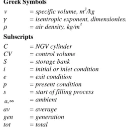
Greek Symbols
v = specific volume, m3/kg
= isentropic exponent, dimensionless = air density, kg/m3
Subscripts
C = NGV cylinder
CV = control volume
S = storage bank
i = initial or inlet condition
e = exit condition
p = present condition
s = start of filling process
,
a∞ = ambient
av = average
gen = generation
tot = total
Natural Gas Refueling Station
Figure 1 shows a typical CNG filling station. Natural gas from the distribution pipeline, usually “low” pressure at < 0.4 MPa or possibly “medium” pressure (1.6 MPa), is compressed using a large multi-stage compressor into a storage bank. This system is maintained at a pressure higher than that in the vehicle’s on-board storage so that gas flows to the vehicle under differential pressures. Typically, the storage bank will operate in the range of 20.5 MPa to 25 MPa, while the vehicle’s maximum on-board cylinder pressure is 20 MPa.
Figure 1. A schematic diagram of NGV refueling station.
Definition of Dimensionless Parameters
There are a few important parameters affecting the filling process which should firstly be introduced. In NGV filling process, thermodynamic properties in storage bank play important role on filling process. Two main thermodynamics in properties storage bank are pressure and temperature. As shown in Fig. 2, storage bank has its own temperature (TS) and pressure (PS) which assumed changed while the pressure and temperature within NGV cylinder varies during filling process. Typically, the pressure in storage bank (PS) is in range of 20.5 MPa to 25 MPa, while the vehicle’s maximum NGV cylinder pressure is 20 MPa. In other words, the target pressure (PT) in the fuelling process is 20 MPa.
To maintain the final pressure within NGV cylinder high enough, the pressure (PS) within storage bank in initial filling process could be assumed between 20.8 MPa to 25 MPa.
T /
C C
RP =P P (1)
T /
S S
RP =P P (2)
It should be noted that at the end of NGV filling process, the number should reach 1, which means that the final pressure of NGV cylinder should be equal to target pressure.
The next dimensionless number introduced in this section is RV, which is the ratio of storage bank volume (VS) to NGV cylinder volume (VC) and defined as follows:
/
S C
RV
=
V
V
(3)Note that the conditions of storage bank during filling process are changing, finding the ratio of volume storage bank rather than volume of cylinder to achieve the target conditions of refueling will be necessary.
Thermodynamic Model
Balance energy model
To model the fast filling process and develop a mathematical method, the NGV cylinder or storage bank is considered as a thermodynamics open system that goes through a quasi-steady process.
m&
T∞
Figure 2. A schematic figure of thermodynamic system.
To develop a theoretical model, the conservation of mass and first law of thermodynamics have been applied to the control volume (storage bank or NGV cylinder), to find 2 thermodynamics properties. Considering the NGV cylinder or storage bank as a control volume, the conservation of mass (continuity) equation may be written as follow:
F o r N G V C ylin d er
Fo r S torag e B an k
C i S e d m m d t d m m d t = = − & & (4)
In equation (4), is the inlet mass flow rate in NGV cylinder and is the outlet mass flow rate of storage bank. It is important that the inlet mass flow rate of NGV cylinder, , is equal to the outlet mass flow rate of storage bank, , as follows:
= =
(5)
The value of can be obtained by considering an isentropic expansion through an orifice. Applying gas dynamics laws:
1 2
1 1
2
(
)
(
)(
) 1 (
)
1
C S C
d S orifice
S S S
P
P
P
m
C
A
P
P
γ
γ
γ
γρ
γ
ρ
−
=
−
−
&
if
2
1(
)
1
C SP
P
γ γγ
−≤
+
(6)1 2 ( 1 )
2
1
d S S o r i f i c e
m
C
P
A
γ γ
γ
ρ
γ
+ −
=
+
&
if
2
1(
)
1
C SP
P
γ γγ
−>
+
(7)In Eqs. (6) and (7) is discharge coefficient of the orifice. The first laws of thermodynamics for a control volume in general form can be written as follows:
cv cv e e e e i i i i cv
W
gz
V
u
m
dt
d
gz
V
h
m
gz
V
h
m
Q
&
&
&
&
+
+
+
+
+
+
=
+
+
+
∑
∑
)]
2
/
(
[
/
)
2
/
(
)
2
/
(
2 2 2 (8)The work term is zero in the filling process and the change in potential and kinetic energy can be neglected. The equation then could be simplified for NGV cylinder and storage bank as below:
2
2
( ) For NGV Cylinder 2
( ) For Storage Bank 2
C i
C i i
S e
S e e
dU V
Q m h
dt
dU V
Q m h
dt δ δ = + + = − + & & & & (9) As 2 2 2 2 i e
S i e
V V
h = + =h +h and = = , the above
equation could further be simplified as:
CV
CV S
dU
Q
m h
dt
=
δ
±
&
&
(10)In Eq. (10), the positive and negative signs have been used respectively for NGV cylinder and storage bank.
The heat lost from the NGV cylinder and storage bank to environment could be calculated as
(
)
CV HCV CV CV
Q
U
A
T
T
δ
&
= −
−
∞ (11)U, A, T and are respectively the overall heat transfer coefficient, surface area, in-cylinder temperature and ambient temperature, for control volume that could be NGV cylinder or storage bank. By combining Eqs. (4), (10) and (11), the following equation is obtained:
(
)
(
)
CV CVCV CV CV S
d mu
dm
U
A
T
T
h
dt
= −
−
∞±
dt
(12)Or in the following form:
(
)
( CV CV) ( CV S)
CV CV CV
d m u d m h
U A T T
dt dt = − − ∞
m (13)
(
)
(
CV CV CV S)
CV CV CVd m u
m
m h
= −
U
A
T
−
T
∞dt
(14) The above equation could be integrated from “outset” of filling, up to “present” time as:(
)
( )
p t
CV CV CV R CV CV CV
o o
d m u m h = − U A T −T∞ dt
∫
m∫
(15)The integration of the above equation for a storage bank with single reservoir fuelling station resulted in:
(
)
(
)
p p R o o R CV CV av
m u
−
h
m
m u
−
h
= −
U
A
∆
T t
(16)when and are mass of charged gas at “present” and “outset” of filling process, ∆ is average temperature difference between cylinder and environment which is defined as:
(
)
1
tav CV o
T
T
T
dt
t
∞∆
=
∫
−
(17)The first law of thermodynamics for the NGV cylinder or storage bank finally can be written as:
(
)
o
p S p CV av o S
p
m
u
h
U A
T t
u
h
m
= −
∆
±
−
(18)Equations (6), (7) and (18) could be employed to obtain the two thermodynamic properties of in-cylinder or storage bank natural gas at any time. For an adiabatic system, Eq. (18) could be more simplified as:
(
)
o
p S o S
p
m
u
h
u
h
m
= ±
−
(19)Note that in Eq. (19), the control volume could be used for the NGV cylinder or storage bank. Also the positive and negative signs have been used respectively for NGV cylinder and storage bank.
By knowing two independent thermodynamic properties (here specific internal energy and specific volume), the other in-cylinder and in-storage bank properties can be found.
Entropy generation model
The second law of thermodynamic and flow processes occurring in the a storage bank of the CNG filling station, adopted in this study, makes it possible to evaluate the entropy generation rate,
gen
S& , for the characteristic nodes of the system.
The second law of thermodynamics for filling process of a NGV cylinder and storage bank could be presented as:
,
,
/ / 0 For NGV Cylinder
/ / 0 For Storage Bank
gen C C C i i gen S S S e e
S dS dt Q T m s
S dS dt Q T m s
δ
δ
∞
∞
= − − ≥
= − + ≥
& & &
& & & (20)
Here, all irreversibility is assumed to occur from inlet to in-cylinder position. This makes an isentropic expansion from reservoir to inlet position, which meanssi
= =
se s.Considering this assumption and this verity that
m
&
=
m
&
i=
m
&
eand also combining Eqs. (4), (11) and (20), the following equation can be obtained:
(
)
(
)
,
,
( )
/ For NGV Cylinder
( )
/ For Storage Bank
C C
gen C HC C C R S
gen S HS S S
d m s dm
S s U A T T T
dt dt
d m s dm
S s U A T T T
dt dt
∞ ∞
∞ ∞
= − + −
= + + −
&
&
(21)
The total entropy generation could be obtained as summation of entropy generation of NGV cylinder S&gen C, and storage bank S&gen S, , as below:
, ,
tot gen C gen S
S& =S& +S& (22)
The above equation can be rewritten as:
(
)
(
)
( ) ( )
/ + /
C C S S
tot HC C C HS S S
d m s d m s
S U A T T T U A T T T
dt ∞ ∞ dt ∞ ∞
= + − + −
&
(23)
Equation (23) can be more simplified for an adiabatic system as:
( ) ( )
+
C C S S tot
d m s d m s
S
dt dt
=
&
(24)
Or in the following form:
( ) ( )
tot C C C S S S
S dt& =d m s −m s +d m s +m s (25)
The above equation can be integrated from “start” of filling to the “present” time as:
(
)
(
)
p p
tot C C C S S S
s s
S
=
∫
d m s
−
m s dt
+
∫
d m s
+
m s dt
(26)For a fuelling station with storage bank, the integration of the above equation resulted in a simple equation as:
( ) ( ) ( ) ( )
tot C C Cs Cs S S Ss Ss
S =m s − −s m s − +s m s − −s m s −s (27)
Results and Discussion
In this study, the NGV cylinder and storage bank have been considered adiabatic, as a result, the characteristics of the orifice will not affect the final temperature state in the cylinder. The orifice diameter and the NGV cylinder volume were considered to be 1 mm and 67 litters respectively. Also, for modeling the heat transfer it is used lumped-system model, which means the results presented in this work are for adiabatic operating conditions. Because Methane occupies a large percentage (between 70% to 99%) of natural gas, for the sake of simplicity it is assumed that Methane is the only substance in Natural gas and thermodynamic properties table has been employed for the case of real gas model based on methane. The results have been presented in Fig. 2.
important. Figure 3 shows the final NGV cylinder pressure for the various RV numbers. As mentioned in previous sections the RV number is defined as ratio of storage bank volume to NGV onboard cylinder volume. As shown in this figure, for bringing up the NGV cylinder to its target pressure (20 MPa) or RPC equal to 1, the various
RV numbers (ratio volume of storage bank to NGV cylinder) should be selected. For studying the effect variation of initial pressure storage bank on filling process, the RPS dimensionless number was introduced
in the previous section. In Fig. 3, the initial pressure of storage bank has changed from 20.8 MPa (RPS = 1.04) to 25 MPa (RPS = 1.25). In
other words, for completing refueling process, the volume of storage bank should be selected respectively 22, 6 and 4 times the NGV cylinder’s for different initial pressures storage bank as 20.8 MPa (RPS = 1.04), 23 MPa (RPS = 1.15) and 25 MPa (RPS = 1.25). As is
clear in this figure, the initial pressure of storage bank has a big effect on the storage bank volume for bringing up the NGV cylinder to its target pressure (20 MPa). Because the minimum of initial pressure in storage bank is a critical condition for filling process, the results have been presented here for storage bank with initial pressure 20.8 MPa.
Figure 3. Effect of RV number (volume storage bank to NGV cylinder volume) and RPS number (PS/PT) on RPC number (PC/PT).
Figure 4 shows dynamic pressure profiles of NGV cylinder and storage bank during filling process. Note from the figure that the time required to reach the final pressure (20 MPa) in NGV cylinder is about 290 seconds. Farzaneh-Gord et al. (2011) have analyzed the same process but with fixed reservoir conditions and obtained lower filling time. This shows that the reservoir condition has effects on the filling time.
Figure 4. NGV in-cylinder and storage bank pressure profiles during filling process.
Figure 5 shows, for the case where initial temperature was kept constant at 300 K, dynamic NGV in-cylinder and storage bank temperature profiles. Note from Fig. 5 that the in-cylinder gas temperature falls pending the early stages of charging before rising to a final value. The proof for the dip in this curve, in the early part of the filling of almost empty NGV cylinder is consequence of the Joule-Thompson cooling effect, which the gas undergoes in the isenthalpic expansion through the orifice, from the 20.8 MPa supply pressure to the initially low 0.1 MPa NGV cylinder pressure. This cold gas mixes with and compresses the gas originally in the NGV cylinder, with the result that the combined mixed gas temperature initially reduces. When the compression and conversion of supply enthalpy energy to NGV cylinder internal energy overcomes the Joule-Thompson cooling effect, which becomes lesser as the NGV cylinder pressure increases, the mixed gas temperature in the NGV cylinder starts to increase. In other words, the storage bank temperature remains nearly constant during filling process.
Figure 5.Temperature profiles of NGV cylinder and storage bank during filling process.
Figure 6 shows mass flow rate profile that flows from storage bank and enters into NGV onboard cylinder during filling process while initial (ambient) condition is kept constant at 300 K and 0.1 MPa. According to Fig. 6, in early part of filling, mass flow rates are nearly constant due to choking. Note from the figure that the mass flow rate which entered the NGV cylinder is equal to the mass flow rate that exited the storage bank.
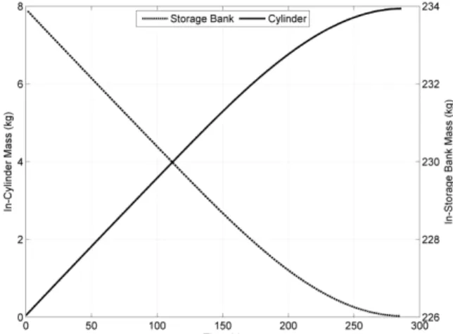
In Fig. 7, the NGV in-cylinder and in-storage bank mass change profiles during filling process are shown while initial temperature and pressure are kept steady at 300 K and 0.1 MPa. Note from the figure that the mass requirement of CNG fuel in storage bank for completing filling process is equal to 234 kg and the final in-cylinder mass increased to 8 kg.
Figure 7. NGV in-cylinder and in-storage bank mass variations during filling process with initial conditions of 300 K and 0.1 MPa.
In the previous studies (Farzaneh-Gord et al., 2007 and Farzaneh-Gord, 2008a), it was found that initials in-cylinder temperature (which could be represented by ambient temperature) have big effects on the final NGV in-cylinder and storage bank properties. Figure 8 shows how the charged mass varies with initial temperature (in the NGV cylinders and storage bank) which could illustrate the effect of ambient temperature. It can be seen as initial temperature increases charged mass decreases. This means that driving range of CNG vehicles will decrease if filling carried out in hot weather compared to the colder conditions.
The ambient temperature has opposite effects on final in-cylinder and storage bank temperatures and charged masses. The final in-cylinder and storage bank temperatures increase as ambient temperature increases whereas the final mass of NGV cylinder and storage bank with diminution of ambient temperature increases. The significant point is that by increasing initial (ambient) temperature, the final in-cylinder and storage bank temperatures increase linearly.
Figure 8. Effect of initial (ambient) temperature on final in-cylinder and storage bank temperatures.
As reminisced previously, entropy generation is dependent on thermodynamic irreversibility. Irreversibility destroys available work in the CNG filling station. As the available work is provided by the compressor, so one could conclude that as entropy generation is decreased, available work destruction is decreased too.
Figure 9 shows entropy generation in NGV cylinder, storage bank and total entropy generation obtained from summation of entropy generation of NGV cylinder and storage bank for filling an empty NGV cylinder. As seen in Fig. 9, the entropy generation in storage bank is much further than entropy generation of NGV cylinder.
Figure 9. Entropy generation in NGV cylinder, storage bank and summation of two.
Figure 10 shows the effect of initial temperature on the entropy generation of NGV cylinder, storage bank and summation of two. As in this figure, for NGV cylinder and storage bank, the entropy generation at low temperatures is much higher than at high temperatures, so the entropy generation in 270 K is, respectively, 5.12 kJ/kgK and 13.65 kJ/kgK for NGV cylinder and storage bank, while the entropy generation in 340 K is, respectively, 3.08 kJ/kgK and 3.07 kJ/kgK.
Figure 10. Effect of initial (ambient) temperature on entropy generation in NGV cylinder, storage bank and total summation.
Conclusion
The first and second laws of thermodynamics have been used as theoretical tools in order to investigate conditions of NGV cylinder and storage bank pending filling process. A theoretical analysis has been built to study the blow downing storage bank and filling NGV cylinder. The important parameters that this paper has investigated include variation of temperature, pressure, mass flow rate, charged mass and entropy generation for NGV cylinder and storage bank. Also, it is discussed effects of ambient temperature on these parameters. As entropy generation is associated with the compressor
E
n
tr
o
p
y
G
e
n
e
ra
ti
o
n
(k
j/
K
input work, it is assumed that, as entropy generation reduces, compressor work decreases too.
The results show that the initial pressure of storage bank has a big effect on the storage bank volume for bringing up the NGV cylinder to its target pressure (20 MPa). It is found that the volume storage bank required for bringing up the NGV on-board cylinder to its final pressure (20 MPa) for the various initial storage bank pressures, like 20.8 MPa (RPS = 1.04), 23 MPa (RPS = 1.15) and 25
MPa (RPS = 1.25) are respectively 22, 6 and 4 times the volume of
NGV cylinder.
The results also reveal that the entropy generation during filling process in storage bank is much further than entropy generation of NGV cylinder.
Considering the above comments, one could conclude that the ambient temperature has big effects on filling process, final in-cylinder and storage bank conditions.
References
Bejan, A., 1979, “A study of entropy generation in fundamental convective heat transfer”, J. Heat Transfer, Vol. 101, pp. 718-725.
Bejan, A., 1982, “Second-law analysis in heat transfer and thermal design”, Adv. Heat Transfer, Vol. 15, pp. 1-58.
Bejan, A., 1996, “Entropy Generation Minimization”, CRC, Boca Raton, NY.
Egúsquiza, J.C., Braga, S.L and Braga, C.V.M., 2009, “Performance and gaseous emissions characteristics of a natural gas/diesel dual fuel turbocharged and after cooled engine”, J. Braz. Soc. Mech. Sci. & Eng., Vol. 31, No. 2, pp. 142-151.
Farzaneh-Gord, M., Eftekhari, H., Hashemi, S., Magrebi, M. and Dorafshan, M., 2007, “The effect of initial conditions on filling process of CNG cylinders”, The second International conference on Modelling, Simulation and Applied optimization, Abu Dhabi, UAE, March 24-27.
Farzaneh-Gord, M., 2008a, “Compressed natural gas Single reservoir filling process”, Gas international Engineering and Management, Vol. 48, Issue 6, July/August, pp. 16-18.
Farzaneh-Gord, M., Hashemi, S.H. and Farzaneh-Kord, A., 2008b, “Thermodynamics Analysis of Cascade Reservoirs Filling Process of Natural Gas Vehicle Cylinders”, World Applied Sciences Journal, Vol. 5, No. 2, pp. 143-149.
Farzaneh-Gord, M., Deymi-Dashtebayaz, M. and Rahbari, H.R., 2011, “Studying effects of storage types on performance of CNG filling stations”, Journal of Natural Gas Science and Engineering, Vol. 3, pp. 334-340.
Farzaneh-Gord, M., Rahbari, H.R. and Deymi-Dashtebayaz, M., 2012a, “Effects of Natural Gas Compositions on CNG Fast Filling Process for Buffer Storage System”, paper accepted by Oil and Gas Science and Technology.
Farzaneh-Gord, M., Deymi-Dashtebayaz, M. and Rahbari, HR., 2012b, “Optimizing Compressed Natural Gas Filling Stations Reservoir Pressure Based on Thermodynamic Analysis”, Int. J. Exergy, Vol. 10, No. 3, pp. 299-320.
Kountz, K., 1994, “Modelling The Fast Fill Process in Natural Gas Vehicle Storage Cylinders”, American Chemical Society Paper at 207th National ACS Meeting, March.
Kountz, K., Kenneth J. and Blazek, C.F., 1997, “NGV Fuelling Station and Dispenser Control Systems”, Report GRI-97/0398, Gas Research Institute, Chicago, Illinois, November.
Kountz, K., Liss, W. and Blazek, C., 1998a, “Method and Apparatus For Dispensing Compressed Natural Gas”, U. S. Patent 5, 752, 552, May 19.
Kountz, K., Liss, W. and Blazek, C., 1998b, “Automated Process and System For Dispensing Compressed Natural Gas”, U.S. Patent 5,810,058, Sept 22.
Kountz, K., Liss, W. and Blazek, C., 1998c, ”A New Natural Gas Dispenser Control System”, International Gas Research Conference, San Diego, November 3.
Liss, W.E. and Richards, M., 2002, “Development of a Natural Gas to Hydrogen Fuelling Station”, Topical Report for U.S. DOE, GTI-02/0193, Sept. Liss, W.E., Richards, M.E., Kountz, K. and Kriha, K., 2003, “Modelling and Testing of Fast-Fill Control Algorithms for Hydrogen Fuelling”, National Hydrogen Association Meeting, March.
Marcelino Neto, M.A. and Barbosa Jr., J.R., 2010, “Modelling of state and thermodynamic cycle properties of HFO-1234yf using a cubic equation of state”, J. Braz. Soc. Mech. Sci. & Eng., Vol. 32, pp. 461-467.
National Iran Oil Products Distribution Company (NIOPC), website available at: www.NIOPC.ir.
Newhouse, N.L. and Liss, W.E., 1999, “Fast Filling of NGV Fuel Containers”, SAE paper 1999-01-3739.
Shipley, E., 2002, “Study of natural gas vehicles (NGV) during the fast fills process”, Thesis for Master of Science, College of Engineering and Mineral Resources at West Virginia University.
Tilagone, R., Venturi, S. and Monnier, G., 2006, “Natural Gas - an Environmentally Friendly Fuel for Urban Vehicles: the Smart Demonstrator Approach”, Oil & Gas Science and Technology – Rev. IFP, Vol. 61, No. 1, pp. 155-164.