DAMAGE ASSESSMENT OF DRILLED HYBRID
COMPOSITE LAMINATES
Luís M. Durão1*, António G. Magalhães1, António T. Marques2 and João Manuel R. S.
Tavares2
1 Dept. of Mechanical Engineering /CIDEM /ISEP - Polytechnic. Institute of. Porto, Portugal 2
DEMEGI /FEUP, Faculty of Engineering in University of Porto, Portugal *[email protected]
ABSTRACT
Hole drilling operations are common in fibre reinforced plastics - FRP’s - to facilitate fastener assembly to other parts in more complex structures. As these materials are non-homogeneous, drilling causes some damages, like delamination, for example. Delamination can be reduced by a careful selection of drilling parameters, drill material and drill bit geometry. In this work two types of laminates are drilled using different machining parameters and comparing drill geometries. Results show the importance of a cautious selection of these variables when composites’ drilling is involved.
1. INTRODUCTION
For the past decades fibre reinforced plastics are increasing their importance as one of the most interesting group of materials, due to their unique properties of low weight, high strength and stiffness. Although earlier development was related with aerospace and aeronautical industries, recent years had seen the spread of their use in many other industries like automotive, railway, naval, sporting goods and others. Concerns related to high cost and marginal manufacturability have been satisfactorily addressed through high volume production and innovative design. In spite of these advances, their use is still limited, due to high cost normally associated to machining and finishing operations. Composite materials are a mixture or a combination of two or more constituents, the matrix and the reinforcement. The mechanical properties of the reinforcement are superior to those of the matrix. If one of the constituents is the result of more than one phase with different characteristics, the composite receives the designation of hybrid. Otherwise is monolithic, a more usual situation. The term hybrid is here referred to a composite that has two types of reinforcement fibre in its construction, namely, carbon and glass fibres in an epoxy matrix. The term monolithic is used in this work for a carbon fibre reinforced laminate.
Machining of composite materials can cause some damages, like delamination, fibre pull-out, cracks or thermal degradation. These machining defects cause a loss of the load carrying capacity of the laminate, which is undesirable [1]. A high rate of tool wear is normally associated with fibre reinforced plastic laminates machining, due to the high abrasiveness of the reinforcement fibre, increasing total operation time by the need of frequent tool changes. It is important to obtain good quality holes, based on a correct knowledge of the material used.
The cutting process for a conventional conical point twist drill is unique and can be divided in two mechanisms: 1) indentation by the chisel edge and 2) orthogonal cutting by the cutting lips of the tool. In a common drill an indentation zone around the chisel can be identified. The region outside this zone, called secondary cutting edges area, is characterized by a negative rake angle. Along the cutting lips the cutting action is a three-dimensional oblique cutting process. The cutting action is more efficient at the outer regions than near drill centre [2].
The importance of tool geometry in delamination reduction is evidenced by several published papers on the subject. Piquet et al. [3] suggested the use of a great number of cutting edges, from three to six, a point angle of 118º for the main cutting edges and a small rake angle. The use of pre-drilling neutralizes the chisel edge effect. A low feed rate can reduce delamination. Stone and Krishnamurthy [4] studied the implementation of a neural network thrust force controller. Persson et al. [5] presented an orbital drilling method, where the hole is machined both axially and radially. Davim and Reis [6] studied the effect of cutting parameters on specific cutting pressure, delamination and cutting power in carbon fibre reinforced plastics. Tsao and Hocheng [7] analyzed the effect of a backup plate on delamination, in order to understand and explain the advantage of its use in composite laminate drilling. In another paper, the same authors [8] conducted a series of practical experiences to prove the benefit of using special drills, comparing the effect of their use on delamination. They also illustrated this advantage by means of mathematical models. Enemuoh et al. [9] developed a multi-objective approach for damage-free drilling. Recommendations from this work were the use of low feeds, in the range of 0.02 to 0.05 mm/rev, and cutting speeds from 40 to 60 m/min. A review on the major scenes towards delamination-free drilling of composite materials is presented in [10]. In the referred article, the authors present aspects of the mathematical analysis, the effects of special drill bits, pilot hole and back-up plate and the feasible use of non-traditional machining. Finally, Tsao [11] evaluated the importance of pilot hole on delamination reduction when using core drills.
The contribution of thrust force to delamination onset and propagation has been first demonstrated by Hocheng and Dharan [12], by their development of a model based on Fracture Mechanics to determine the critical thrust force for delamination:
2 1 2 12 3 1 ) 1 ( 3 8 − =
υ
π
G Eh F Ic crit (1), where GIc is the interlaminar fracture toughness in mode I, E1 is the elastic modulus and12
υ
is the major Poisson ratio of the unidirectional plate. According to this equation, if at some moment the thrust force is higher than Fcrit, delamination occurs. A careful
choice of drilling parameters, of drill geometry or the use of a pilot hole, as evidenced in [13, 14], can reduce delamination hazard.
In this work two types of laminates are produced, one hybrid with 25% of carbon and 75% glass reinforced plies and one monolithic carbon/epoxy plate, considering a quasi-isotropic lay-up. Then, the plates are drilled using a standard 6 mm diameter twist drill in tungsten carbide, a Brad drill and a “special” step drill. The latter is a specially developed drill, intended to reduce delamination around the hole and to complete the drilling operation in one step only. For the holes made with a twist drill, a pilot hole was used. In order to evaluate the influence of cutting parameters on delamination, three different cutting speeds and feed rates were used. During drilling, thrust forces were monitored and delamination was measured by using enhanced radiography together with Computational Vision techniques in order to reckon the necessary measurements from the images obtained by radiography.
At the end, and based on damage extent results, a cutting speed and a feed rate to minimize delamination for each laminate type are recommended. Delamination values obtained with the three different drill geometries are compared and the importance of drill bit geometry on delamination is established. Conclusions regarding tool design to reduce damage extension are presented in the last section of this paper.
2. HYBRID LAMINATES
The term hybrid refers to a composite that has more than one type of matrix or fibre in its construction. The use of hybrid composites can expand the range of achievable properties when using composite materials, and can be more cost-effective than conventional or advanced composites. One of the main attractive when using hybrids is their synergy effect also called as ‘hybrid effect’. The most common effect is to obtain a composite property, like tensile strength, whose value is higher than would be predicted from a simple application of the rule of mixtures. This would be a positive hybrid effect. In some cases, a negative effect may also occur [15].
The term hybrid applies to advanced composites using various combinations of carbon, boron, aramid or glass filaments in a thermosetting or thermoplastic matrix. Hybrids have unique features that can be used to meet design requirements in a more cost-effective way than advanced or conventional composites. Some of those advantages are the balanced strength and stiffness, balanced thermal distortion, reduced weight and/or cost, improved fatigue or impact resistance [15].
According to M. M. Schwartz [15], there are four basic types of hybrid composites: • interply hybrids, that consists of plies from two or more different
unidirectional composites stacked according to a specific sequence;
• intraply hybrids, consisting in two or more different fibres mixed in the same ply;
• interply-intraply hybrids, in which interply and intraply hybrids are stacked according to a specific sequence;
• superhybrids, that are resin-matrix composite plies stacked according to a specific sequence.
The first two types of hybrids generally have the same matrix. Although thermosetting and thermoplastic resins can be used for hybrid composites, epoxies remain the most used. Thermosetting polyester resins are already used in a large number of applications in automotive and aeronautic industry. Fibres most currently found in hybrids are carbon, boron, glass and aramid. The potential for the number of fibre-resin combination for hybrids is vast. Using only two resins – epoxy or polyester – and three types of fibre – carbon, glass or aramid – a large number of hybrid composites can be produced, combining fibre content and orientation in the matrix.
The main interest of this work is in interply hybrids using carbon and E-glass as reinforcement. In this type of hybrid, carbon fibre contributes with high tensile and compressive strength and stiffness and reduces density while glass reduces final cost. This combination is an excellent mix, as price and mechanical properties can be balanced according to designer needs. A hybrid carbon/ glass with only 25% of carbon can increase both elastic and flexural modulus by 60% with a cost increase of approximately 5%.
3. EXPERIMENTS 4.1 Drilling tests
In order to perform the experimental work predicted, two types of laminates were produced: a carbon/epoxy plate fabricated from prepreg with a stacking sequence of [(0/-45/90/45)]4s, in order to have a plate with quasi-isotropic characteristics; carbon/epoxy and glass/epoxy pre-preg with a stacking sequence of [(0/-45/90/45)C /(0/-45/90/45)3V]s, with identical intention regarding quasi-isotropic characteristics. In both cases, the laminate was cured in a hot plate press under a pressure of 300 kPa and a
temperature of 140 ºC for one hour followed by air cooling. At the end, the plate’s thicknesses were 4 mm. From those plates, a total of five test coupons for each test batch were cut.
Plates were drilled in a machining centre OKUMA MC-40VA, allowing the use of a large range of cutting speeds and feeds. During drilling, axial thrust force (Fz) was
monitored with a Kistler 4782 dynamometer associated to a multichannel amplifier and data acquisition board for a PC. The workpiece was clamped to the dynamometer prior to drilling.
All the drills used have a diameter of 6 mm and were made in tungsten carbide. All parts were drilled without the use of a sacrificial plate. Three types of drill were compared, two of them commercially available: twist drill with a 1.1 mm pilot hole, Brad drill and a ‘special’ step drill, designed to reduce delamination during composites drilling. All these tools are shown in figure 1. Twist drill (fig. 1a) is a tool with a standard geometry. Associated with the use of the twist drill a pilot hole of 1.1 mm diameter was performed. The intention of pilot hole was to reduce the maximum thrust force achieved and decrease delamination around the hole by cancelling the chisel edge effect of the drill.
Brad drill (fig. 1b) is a special edged drill firstly designed for cutting wood, with edges in scythe shape, that causes the tensioning of the fibres prior to cut, thus enabling a ‘clean cut’ and a smooth machined surface.
a) b) c)
Figure 1: Drills: a) twist; b) Brad; c) ‘special’ step drill
Finally, an alternative drill design is proposed and experimented. During a lecture presented in INEGI-Porto in 2000, H. Dharan had suggested a step geometry for the drill design [16]. The ‘special’ step drill (fig. 1c) has two drilling diameters – 1.25 and 6 mm - dividing the drilling operation, and consequently the thrust force, in two stages. This tool geometry also cancels the chisel edge effect for the final diameter drilling. The diameter alteration region has a conical shape, for a soft transition. The reduction of delamination risk by reducing the maximum thrust force is also looked for. Another advantage of this tool is the possibility of executing the hole in one operation only. This represents a gain in operation time when compared with the use of a pilot hole, for there is no need to undergo a tool changing operation. The drill tip was designed in a way to promote the initiation of the cutting action immediately after touching the plate, thus reducing the indentation effect. This tool is not commercially available. Cutting parameters were evaluated between three different cutting speeds and three feed rates, shown in table 1.
Table 1: Cutting parameters. Cutting speed [m/min] Spindle speed [rpm] Feed speed [mm/rev] Low 53 2800 0.025 Medium 80 4200 0.05 High 102 5600 0.075
4.2 Damage assessment
Enhanced radiography can be used for the detection of delamination in a composite plate if an adequate contrasting fluid, like di-iodomethane, is used. After an immersion time of 90 min, the plates are withdrawn from the fluid, cleaned and radiographed. After laminate drilling it is important to establish criteria that allows for the comparison of the delamination extent for different strategies. We should note that these criteria can only be applied to composites with the same lay-up regarding reinforcement orientation and number of plies.
Damaged extension can be evaluated by using radiography, C-Scan or computerized tomography (CT) [17, 18, 19] in order to obtain the images of the hole surrounding area.
Chen [17] proposed a comparing factor that enables the evaluation and analysis of delamination extent in composites, the Delamination Factor Fd and it was defined as the
quotient between the maximum delaminated diameter Dmax and the hole nominal
diameter D: D D
Fd = max (2).
A different ratio was suggested by Mehta et al. [18], the damage ratio DRAT defined as
the quotient of Hole Peripheral Damage Area DMAR to Nominal Drilled Hole Area AAVG: AVG
MAR
RAT D A
D =
(3). This damage evaluation criterion is based on the existence of digitized images of the damaged region.
In this work, the images obtained showed several levels of grey, where dark grey correspond to damaged areas and light grey to undamaged areas – Figure 2. The delaminated area is located at a circular region around the hole.
Figure 2: Example of an enhanced radiography of a drilled plate.
In order to obtain results according to the criteria mentioned above, the resulting radiographic images were processed to obtain the information regarding the damaged area or damaged diameter. This computational process has the advantage of reducing operator dependence on the measurement of the dimensions wanted, thus increasing confidence and reliable in results. An existing processing and image analysis platform was used [20, 21]. This platform turned possible the use of some standard Computational Vision techniques [22, 23, 24] for image processing and analysis, like image filtering, segmentation and region analysis. Details of the process considered can be found elsewhere [25]. The use of this computational process turned out possible to obtain the dimensions judged as necessary to have a damage evaluation according to equations (2) and (3).
4. EXPERIMENTAL RESULTS
4.1 Drilling parameters effect on thrust force
During the drilling tests, the thrust force was continuously monitored as referred before. For each combination of tool geometry and cutting parameter, a total of five coupons were drilled. So, the results here presented are their average. It is possible to remark that
the standard deviation was always very low, regarding thrust force values considered. As delamination onset and propagation are largely dependent on the maximum value of thrust force, this was the value regarded as useful for result comparison.
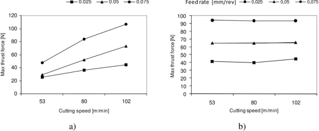
In figure 3, it is possible to observe that, for carbon/epoxy plates, higher cutting speeds always causes higher values of maximum thrust forces. The same tendency can be noted when higher feeds are used for plate drilling. When looking at hybrid plates results, it becomes evident the major effect of feed rate on maximum thrust force values.
0 20 40 60 80 100 120 53 80 102
Cutting speed [m /m in]
M a x t h ru s t fo rc e [ N ] 0.025 0.05 0.075 0 10 20 30 40 50 60 70 80 90 100 53 80 102 M a x th ru s t fo rc e [N ]
Cutting speed [m/min]
0,025 0,05 0,075
Feed rate [mm/rev]
a) b)
Figure 3: Maximum thrust force results for different feed rates and cutting speeds In general, these results are adequate to identify an optimum domain of parameters combining low feed rates with low cutting speeds. Higher cutting speeds increase the risk of thermal damage as it causes the softening of the matrix material. A consequence of that phenomenon can be a loss of mechanical strength of the uncut plies of the laminate, leading to extended delamination. The cutting speed identified as best among the three used correspond, for a 6 mm diameter tool, to a spindle speed of 2800 rpm. Independently of the drill geometry or the cutting speed, a clear trend was found regarding the effect of feed rate. The best results, either for thrust force or delamination, were always found when a low feed rate was used. Regarding the experimental set used in this work, it is not surprising to observe that a feed of 0.025 mm/rev has resulted as the best option – figure 3. However, it must be remembered that a low feed rate also increases the heating of the hole machined walls during machining. In some cases, the possibility of matrix softening should be taken into account. In that case, thermograph techniques should be used in order to evaluate this risk. The use of CNC machines, enabling a variable feed rate strategy is a good option to consider when drilling laminate plates.
Delamination factor results – figure 4 – had confirmed the results of thrust force like the existence of a direct correlation between thrust force values and delamination extension. So, from the three cutting speeds used, the lowest one was again identified as the most favorable in terms of delamination reduction. Also the feed rate identified as low – 0,025 mm/rev – in this work has given the best results when delamination minimization is involved.
The use of higher feeds will increase the thrust force over the uncut plies of the laminate. This outcome is well known in drilling operations for any type of material. When composite laminates are involved, this thrust force increase has a direct influence on delamination onset and propagation.
1,04 1,06 1,08 1,10 1,12 1,14 53 80 102
Cutting s peed [m /m in]
D e la m in a tio n f a c to r [F d ] 1,04 1,06 1,08 1,10 1,12 1,14 0,025 0,05 0,075 Feed rate [m m /rev]
D e la m in a tio n F a c to r [F d]
Figure 4: Delamination factor Fd results for different cutting speeds and feed rates.
4.2 Drilling parameters effect on delamination
Experimental results had shown that, under the experimental conditions described, the tool geometry has a definitive influence in each one of the results considered for assessment. Even using the same cutting speed and feed rate it was possible to establish a hierarchy for the three drill geometries used.
The lower value of the maximum thrust force was obtained when using the twist drill. The ‘special’ step drill presented a maximum value about 14% higher, on the average. Brad drill results of maximum thrust force were higher than the lower one by about 45% and if compared to the ‘special’ step drill, 26% higher.
The measurement of the damage around the hole had shown some differences when compared with the order obtained for the maximum thrust force. Also, the type of material – monolithic or hybrid – has evidenced some influence on the final result for this damage criterion. As it can be observed in figure 5, the delamination caused by the use of the several drills was different according to the nature of the material. It seems that the nature of the fibres has to be regarded as a factor for tool selection. Plain carbon/epoxy plates had higher delamination than hybrid plates, which can be linked to the nature of the glass fibers that allow for higher deformation without fracture.
1 .0 9 1 .1 2 1 .1 5 1 .1 8 Brad Twist Step D ri ll
Damage Ratio [DRAT]
a) 1 .0 7 1 .0 8 1 .0 9 1 .1 0 1 .1 1 1 .1 2 Brad Twist Step D ri ll
Damage ratio [DRAT]
b)
Fig. 5: Damage ratio in: a) carbon/epoxy and b) hybrid plates.
For carbon/epoxy plates, the delamination caused by the ‘special’ step drill was higher than those caused by the other two tool geometries. In fact, this result was not expected as the design of this drill was thought to enable a reduction of delamination. A different
and more encouraging result was observed when looking at delamination for hybrid plates. In this case, the ‘special’ step drill has proven its adequacy by returning the lower value of Damage Ratio. Remind that the tip of this drill was designed in a way to reduce the chisel edge effect by promoting the cutting action immediately after drill-plate contact and the first diameter of the drill was approximate to a value of the pilot hole that had given the best results in terms of delamination reduction. Moreover, this first diameter is within the range recommended by Tsao and Hocheng [14]. The straight blade design adopted for this tool, for both cutting diameters, is a possible reason for the poorer outcome in carbon/epoxy plates. Some of the fibers were torn instead of cut, giving a poor finish for the machined hole. This cutting edge geometry needs to be changed in order to have a clean cut of the fibres. Other changes in this tool will be needed, like the profile of the diameter change section and the creation of a helix angle at the major diameter section.
These results should be considered as promising as this was a prototype tool and future evolutions will bear the recommendations learned by these experiments.
Another important remark is related with the fact that the correlation that can be established between thrust forces and delamination extent should only be valid under identical conditions regarding tool geometry. It is clear from the results here presented that tool geometry is a major factor in the occurrence of damage like delamination and its extent.
Another probable factor that was not analyzed in this paper is the influence of the stacking sequence of the laminate that can be responsible for alterations in the experimental results presented.
5. CONCLUSIONS
A set of quasi-isotropic carbon/epoxy laminates and another set of hybrid plates, with carbon and glass reinforced plies in an epoxy matrix, were drilled using a twist drill, a Brad drill and a ‘special’ step drill. A total of three different cutting speeds and three feed rates were used in this experimental stage of the work.
The results considered for comparison were the maximum thrust force during laminate drilling and the delamination measurement, using delamination factor, Fd, and damage
ratio, DRAT, criteria. The damage around the hole was evaluated by the use of enhanced
radiography combined with Computational Vision techniques to provide the need measurements from the acquired images.
From the results here presented, it is possible to draw some conclusions:
• Delamination can be reduced if proper cutting parameters are selected. Considering the parameters used in this work, the best set was a cutting speed of 53 m/min with a feed rate of 0.025 mm/rev, for both type of plates.
• The drill geometry has an influence on the results used for evaluation: maximum thrust force and delamination around the hole.
• Considering only the delamination results, the twist drill with a 1.1 mm pilot hole seems to be the most appropriate tool for carbon/epoxy laminates drilling. • The ‘special’ step drill appears to be a good design, especially when glass/epoxy plies are to be drilled and when considering maximum thrust force during drilling for both cases. It also has the advantage of avoiding a tool changing operation when compared with the twist drill with pilot hole.
• However, the results for the delamination extent were not as satisfactory as expected. Improvements of this tool design are needed in order to have good results regarding damage reduction.
ACKNOWLEDGEMENTS
The work presented in this paper has been partially funded by FCT – Fundação para a Ciência e para a Tecnologia, from Portugal – in the scope of project PTDC/EME-TME/66207/2006.
REFERENCES
1- Abrate, S., “Machining of Composite Materials”, Composites Engineering Handbook, P. K. Mallick, Marcel Dekker, New York, 1997, 777-809.
2- Langella, A., Nele, L., Maio, A., “A torque and thrust prediction model for drilling of composite materials”, Composites A, 2005, 36, 83-93.
3- R. Piquet, B. Ferret., F. Lachaud, P. Swider, P., “Experimental analysis of drilling damage in thin carbon/epoxy plate using special drills”, Composites A, 2000, 31, 1107-1115.
4- Stone, R., Krishnamurthy, K., “A Neural Network Thrust Force Controller to Minimize Delamination During Drilling of Graphite-Epoxy Composites”, Int. J. of Machine Tools & Manufacture, 2005, 36, 985-1003.
5- Persson, E., Eriksson, I., Zackrisson, L., “Effects of hole machining defects on strength and fatigue life of composite laminates”, Composites A, 1997, 28, 141-151.
6- Davim, J. P., Reis, P., “Drilling carbon fibre reinforced plastics manufactured by autoclave – experimental and statistical study”, Materials and design, 2003, 24, 315-324.
7- Tsao, C. C., Hocheng, H., “Effects of exit back-up on delamination in drilling composite materials using a saw drill and a core drill”, Int. J. of Machine Tools & Manufacture, 2005, 45, 1261-1270.
8- Hocheng, H., Tsao, C. C., “Effects of special drill bits on drilling-induced delamination of composite materials”, Int. J. of Machine Tools & Manufacture, 2006, 46, 1403-1416.
9- Enemuoh, E. U., El-Gizawy A. S., and Okafor, A. C. “An approach for development of damage-free drilling of carbon-fibre reinforced thermosets “, Int. J. of Machine Tools & Manufacture, 2001, 41, 1795-1814.
10- H. Hocheng H., Tsao, C. C., “The path towards delamination-free drilling of composite materials “, J. of Materials Processing Technology, 167, 2005, 251-264.
11- Tsao, C. C., “The effect of pilot hole on delamination when core drilling composite materials”, Int. J. of Machine Tools & Manufacture, 2006, 46, 1653-1661.
12- Hocheng, H., Dharan, C. K. H., “Delamination during drilling in composite laminates”, J. of Engineering for Industry, 1990, 112, 236-239.
13- Won, M. S., Dharan, C. K. H., “Chisel edge and pilot hole effects in drilling composite laminates”, Trans. of ASME J. of Manuf. Science and Engineering, 2002, 124, 242-247.
14- Tsao, C. C., Hocheng, H., “The effect of chisel length and associated pilot hole on delamination when drilling composite materials”, Int. J. of Machine Tools & Manufacture, 2003, 43, 1087-1092.
15- Schwartz, M. M., Composite Materials Handbook, McGraw Hill, 1988. 16- Dharan, C. K. H., “Conference on composites machining”, INEGI-PORTO,
17- Chen, W. C., “Some experimental investigations in the drilling of carbon fibre-reinforced plastic (CFRP) composite laminates”, Int. J. Machine Tools & Manufacture, 1997, 37, 1097-1110.
18- Mehta, M., Reinhart, T. J., Soni, A. H., “Effect of fastener hole drilling anomalies on structural integrity of PMR-15/Gr composite laminates”, Proc. of the Machining Composite Materials Symposium, ASM Materials Week, 1992, 113-126.
19- C. C. Tsao C. C., Hocheng, H., “Computerized tomography and C-Scan for measuring delamination in the drilling of composite materials using various drills“, Int. J. of Machine Tools and Manufacture, 2005, 45, 1282-1287.
20- Tavares, J. M. R. S., “Análise de Movimento de Corpos Deformáveis usando Visão Computacional”, PhD thesis, 2000, FEUP, Porto.
21- Tavares, J. M. R. S., Barbosa, J. G., Padilha, A. J., RESI – Revista Electrónica de Sistemas de Informação, 2002, vol. 1.
22- Awcock, G. W., Thomas, R., Applied image processing, 1995, McGRAW-HILL International Editions, New York.
23- Jain, R., Kasturi, R., Schunck, B. G., Machine Vision, 1995, McGRAW-HILL International Editions, New York.
24- Schalkoff, R. J., Digital image processing and computer vision, 1989, John Willey & Sons, Inc., 1989.
25- L. M. P. Durão, A. G. Magalhães, João Manuel R. S. Tavares and A. Torres Marques, 2006, Analyzing objects in images for estimating the delamination influence on load carrying capacity of composite laminates, Proc. of CompIMAGE 2006, Coimbra, Portugal, Taylor & Francis, ISBN: 9780415433495, 169-174.