A comparative study on JPEG-Like and EZW based image coders
6
0
0
Texto
(2) A2 PSNR = 10 log10 MSE M. MSE =. N. ∑∑ I (m, n) − I m =1 n =1. (2) ∗. (m, n) . 2. (3). M ⋅N. In equation (3) M and N are the image dimensions, I (m, n) refers to the pixel at position (m, n) in the original image, and I ∗ (m, n) refers the pixel with the same spatial coordinates in the coded image. This paper is organized as follows. In section 2 we present the structure of the codecs considered in this study, also as some of their relevant aspects. Evaluation conditions, experimental results and comments are presented in section 3, and finally, the main conclusions are presented in the last section.. Fig. 1 – Functional diagram of JPEG Baseline encoding.. It includes the transform application (DCT), coefficient scanning and quantization, and entropy coding. The DCT is applied to blocks of 8x8 pixels in non-interlaced raster mode. According to the spatial organization of the DCT coefficients, its scanning order must take into account its significance. In the JPEG DCT based image coding scheme, e.g JPEG Baseline, the scanning order of the transform coefficients is performed in a zig-zag fashion, as shown in figure 2. The first coefficient is the lowest frequency coefficient, i.e. DC coefficient, which is scanned and quantized separately.. 2 Structures of the Codecs This section presents the structures and describes the codecs evaluated in this paper. Due to its similarity in terms of structure, we group the JPEG Baseline coder (DCT based) and the JPEG DWT (DWT based), and we call it JPEG-like image coders. The EZW image codec, which is also DWT based, is presented separately due to its characteristics and also due to its differences to JPEG-like codecs. Among the various studies concerning the use of DWT to image coding, we refer in particular the work from Antonini et. al. [10], from which one may conclude that biorthogonal wavelet (4.4), also known as 9/7 filter pair, leads to the best results in image coding, mainly due to its good characteristics in minimizing phase distortion. In this work we perform the DWT using the 9/7 filter pair. For entropy coding in JPEG–Like coders (with DCT or DWT) we use Huffman coding [11], considering the tables specified for JPEG Baseline. For the EZW coder, due to unavailability of Huffman tables best suited for this type of coder, we use arithmetic coding in the entropy coding block.. 2.1 JPEG Baseline The structure of the JPEG Baseline image coder is well known, and its functional block diagram is depicted in figure 1.. Fig. 2 – Scanning order of the DCT coefficients inside each block of 8x8 pixels.. The DCT coefficients are quantized using the quantization tables 1 and 2, for the luminance and chrominance components, respectively, as defined for the JPEG standard. 16 12 14 14 18 24 49 72. 11 10 16. 24. 40. 51. 12 14 19. 26. 58. 60. 13 16 24 17 22 29. 40 51. 57 87. 69 80. 22 37 56 35 55 64. 68 109 103 81 104 113. 64 78 87 103 121 120 92 95 98 112 100 103. 61 55 56 62 77 92 101 99 . Tab. 1 – Luminance coefficients quantization table. 17 18 24 47 99 99 99 99. 18 24 47 99 99 99 99 21 26 66 99 99 99 99 26 56 99 99 99 99 99 66 99 99 99 99 99 99 99 99 99 99 99 99 99 99 99 99 99 99 99 99 99 99 99 99 99 99 99 99 99 99 99 99 99 99. Tab. 2 – Chrominance coefficients quantization table..
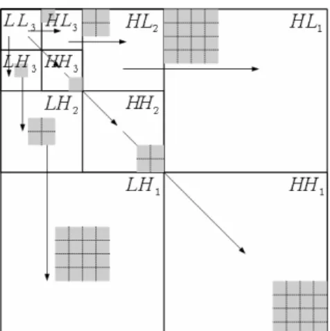
(3) The Huffman coding block is an entropy coding process, which is based on tables that respect the probabilities of occurrence of the transform coefficients, and that are also linked to the nature of the coefficients, i.e., the low and high frequencies coefficients of the luminance and the chrominance components, etc.. each coefficient at HL3 , LH 3 and HH 3 maps four. HL2 , LH 2 , HH 2 ; and each coefficient at HL2 , LH 2 and HH 2 maps four coefficients in HL1 , LH1 , HH1 , as depicted in figure. coefficients. at. 5.. 2.2 JPEG–DWT Several authors have studied the application of the DWT to image coding, achieving good quality results, although the application of the DWT often leads to higher complexity coding schemes. In order to minimize the coding complexity when using the DWT, Queiroz et. al. [8] proposed a JPEG-like image coder based on the DWT: the JPEG-DWT coder, which structure is presented in figure 3.. Fig. 4 – One level image analysis with the DWT 2D. Fig. 3 – Structure of the JPEG–DWT coder (based on the typical JPEG structure).. The structure of the JPEG–DWT coder is similar to that of the JPEG Baseline. The main difference is the use of the DWT instead of the DCT, applied to the all image with 3 levels of analysis. One knows that the DWT has strong relations with multiresolution analysis (MRA) and filter banks [6]. This leads to splitting a sequence in two subsets of its even and odd ordered coefficients, by applying a pair of low-pass and high-pass filters, followed by decimation with a factor of 2. The output of each low-pass filter feeds the new pair of filters in the next level of decomposition. This process can be applied recursively to the low frequency bands, thus leading to an approximation signal with different levels of detail. For a one level image analysis, one gets four subsets of coefficients organized in subbands, as presented in figure 4. Sub-band LL corresponds to the lower frequencies (approximation coefficients), and subband HH corresponds to the higher frequencies (detail coefficients); the other two sub-bands are intermediate frequency sub-bands. In a multilevel image decomposition scheme, there are hierarchical dependencies in each sub-band that must be taken into account in the scanning order of the coefficients. A coefficient at LL3 maps three other coefficients, each one located at HL3 , LH 3 , HH 3 , respectively;. Fig. 5 – Hierarchical sub-band relations of the DWT coefficients in a 3 level ( L = 3 ) image analysis scheme.. Regarding the hierarchical relations of the coefficients of the DWT (see fig. 3), one has to consider modifications to the scanning order of the block of 8x8 coefficients, respecting its locations in the frequency bands, and its dependencies. To do this one has to form blocks of 8x8 coefficients (like as in the JPEG coder), by placing the DWT coefficients in the 8x8 block in accordance with its band locations in the decomposed image. After forming each 8x8 block, one must perform a modified scanning order of the block coefficients as depicted in figure 6. The coefficients in the same relative location, in different sub-bands, are grouped together in the same block. For a 3 level DWT.
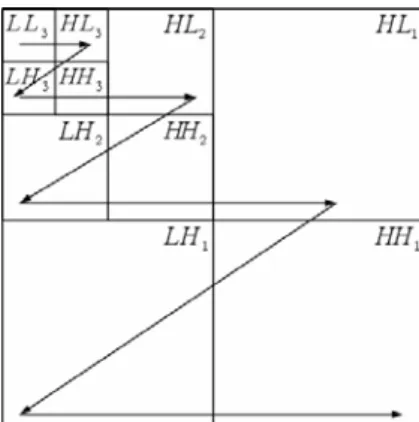
(4) decomposition, this scheme fits perfectly into a block of 8x8 coefficients (23 = 8) . In JPEG Baseline the quantization table has 64 entries representing uniform quantization steps. For the JPEG–DWT coder with 3 levels of decomposition ( L = 3 ), we consider the model defined in [8] to average the quantizer steps for all the coefficients in the same subband, with respect to a variable A to control the bit rate. For A = 6.7 , and 3 levels of decomposition, one obtains the quantization matrix in table 3.. coefficients located in the higher levels are scanned prior to those located at the lower levels. This is performed form higher to lower levels, taking into account the dependencies of the coefficients in the tree, as depicted in figure 7. In two dimensions, a node at the first level of the pyramid, also called root of the tree, or root node, has three children nodes, a node at the middle level or, intermediate level, has four children while a node at the bottom of the tree (leaf node) has no children.. Fig. 7 – Scanning order of the DWT coefficients in EZW Fig. 6 – Modified scanning order in the constructed block of 8x8 coefficients of the 3 level DWT. 8 7 8 8 34 34 34 34. 7. 8. 8. 7. 8. 8. 8. 12 12. 8. 12 12. 34 34 34 34 34 34 34 34 34 34 34 34. 34 34 34 34 34 34 34 34 34 34 34 34 34 34 34 34 55 55 55 55 55 55 55 55 55 55 55 55 55 55 55 55. Tab. 3 – Quantization table for the 3 analysis levels.. 2.3 EZW Coder One knows that information in natural images is predominant at low frequency components. On the other hand, image analysis with the DWT tends to concentrate energy in lower bands (higher levels), thus, the coefficients located at the higher levels of decomposition are more significant than those located in lower levels. The significance of the coefficients decreases as the level decreases inside the transformed image. The EZW coding scheme [7] is strongly based in the high probability that the coefficients of the 2D structure of the decomposed image, at the higher levels (lower bands), are more significant than those located at lower levels, or higher bands (see fig. 5). The significance of the coefficients decreases as the level decreases inside the image. The scanning order of the coefficients is fixed, assuring that the. For images with dimension M × N , with p levels of decomposition, the dimensions of the tree root region are defined by M h × N h , where M h = Mp and 2. N Nh = p 2. . We refer the subsets of DWT coefficients. in the tree-root, in an intermediate level and the coefficients located in the bottom level by, R, I and B , respectively. With reference to a threshold, four coding symbols are used: positive or POS (if the coefficient is found significant and positive); negative or NEG (if the coefficient is found significant and negative); zerotree-root, or ZTR (if the coefficient is found insignificant, also as all its dependents) and isolated zero or IZ (if the coefficient is insignificant but there are coefficients dependents that are significant). The initial threshold value, T0 , is set to a power of 2, not greater neither equal to the maximum absolute value of the coefficients in the matrix, as defined in equation (4).. ( (. )). log max γ ( x , y ) 2 . T0 = 2. (4). During EZW coding two lists are maintained: a dominant list, which is of first-in first-out type (FIFO), and a subordinate list. In the dominant pass, the coefficients are scanned, and significant coefficients are coded, which corresponds to add their value and coordinates to the dominant list, and.
(5) PSNR vs. Comp. Factor for "Baboon" 35 30. PSNR [dB]. to fill with zero the corresponding position in the matrix (preventing from coding in a future dominant pass), otherwise it remains unchanged to the next dominant pass. After the dominant pass a subordinate pass is performed in order to refine the coding, using a threshold value that is half of the one used in the dominant pass. After completing each dominant and subordinate passes, the threshold is halved, and a new coding process restarts.. 25 20 15 10 5 JPEG Baseline. 0 6. 20. 30. 40. 50. Comp. Factor. 3 Results and Comments Test images such as “Lena”, “Airplane” and “Baboon” with spatial resolutions of 512x512 were coded, in order to evaluate the performance of the codecs and the quality of the coded images. To avoid degradation at the bound regions of the images due to the zero fill of initial conditions, in DWT calculations, the sequences were symmetrically extended [12], and the extended coefficients are finally discharged, in order to maintain in-place computation. PSNR vs . Comp. Factor for "Lena" 40 35. PSNR [dB]. 30 25 20 15 10 5. JPEG Baseline JPEG DWT. 0 13. 20. 30. 40 50 Comp. Factor. 60. 70. 80. EZW. Fig. 8 –PSNR curves for JPEG-like and EZW coders, for various compression factors, obtained for “Lena” image.. 60. 70. 80. JPEG DWT EZW. Fig. 10 – PSNR curves for JPEG-like and EZW coders, for various compression factors, obtained for “Baboon” image.. Due to the differences in the image coders under comparison, we evaluate the quality of the coded images through PSNR, by considering approximately the same compression ratio, (i.e. with equal bitrate approx.). Figures 8 to 10 show the PSNR values obtained for different compression ratios, for the JPEG-like coders, and for the EZW coder. From these figures, one can conclude that in general, the JPEG–DWT coder shows similar results to the JPEG-Baseline, which are slightly better (aprox. 0.5 dB) for compression ratios above 20. The same applies in general for the EZW coder, except for the higher compression ratios (for 60 or above), where the EZW coder shows better PSNR results. However, this only applies to objective measurements, as the quality of the coded images is not good enough, from a subjective point of view. Also form a subjective point of view, for the JPEG –Baseline, the subjective quality of the coded images is the poorest, as the compression factor increases.. PSNR vs . Comp. Factor for "Airplane" 40 35 PSNR [dB]. 30 25 20 15 10 5 JPEG Baseline. 0 12. 20. 30. 40. 50. Comp. Factor. 60. 70. 80. JPEG DWT EZW. Fig. 9 – PSNR curves for JPEG-like and EZW coders, for various compression factors, obtained for “Airplane”.. Fig. 11 – Result of the coded image of “lena”, with JPEG–Baseline coder, with a compression factor of 50..
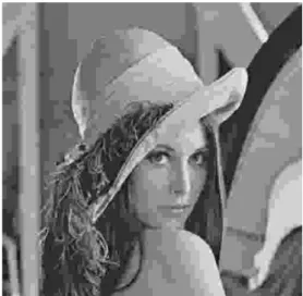
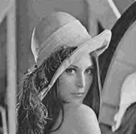
(6) evaluation, one concludes that the DWT based coders perform better than DCT based coders, in particular for higher compression ratios. References:. Fig. 12 – Result of the coded image of “lena”, with JPEG–DWT coder, with a compression factor of 50.. Fig. 13 – Result of the coded image of “lena”, with EZW coder, with a compression factor of 50.. Figures 11 to 13 show the results of the coded images for “lena”, with compression ratios around 50, for JPEG – Baseline, JPEG – DWT, and EZW coders, respectively. As one can observe, the best quality is achieved for the DWT based image coders.. 4 Conclusions This paper addresses the evaluation of image coding schemes with architecture of JPEG type, based on the DCT and the DWT, and also an EZW coder (also based on the DWT), using the 9/7 wavelet filter pair to compute the DWT. For the entropy coding block, we use Huffman coding for JPEG-like coders, and arithmetic coding for the EZW coder. Compression ratios ranging from 10 to 80 were obtained, for all the coders evaluated. From the objective measures of quality of the coded images, and also from the subjective. [1] G. K. Wallace, “The JPEG Still Picture Compression Standard”, IEEE Transactions on Consumer Electronics, Vol. 38, Issue 1, February 1992, pp. xviii – xxxiv. [2] V. Baskaran, K. Konstantinides, Image and Video Compression Standards, Kluwer Academic Press, 2nd Ed, 1996. [3] J. D. Gibson, T. Berger, T. Lookabaugh, D. Lindbergh, R. Baker, Digital Compression for Multimedia, Morgan Kaufmann Publishers, 1998 [4] G. Strang, “The Discrete Cosine Transform”, SIAM Review, 41, 1999, pp. 135 – 147. [5] I. Daubechies, Ten Lectures on Wavelets, SIAM – Society for Industrial and Applied Mathematics, 1992. [6] M. Vetterli, C. Herley, “Wavelets and Filter Banks: Theory and Design”, IEEE Transactions on Signal Processing, Vol. 40, Issue 9, September 1992, pp. 2207 – 2232. [7] J. M. Shapiro, “Embedded Image Coding Using Zero-trees of Wavelet Coefficients”, IEEE Transactions on Signal Processing, Vol. 41, N. 12, December 1993, pp. 3445 – 3462. [8] R. Queiroz, C. K. Choi, Y. Huh, K. R. Rao, “Wavelets Transforms in a JPEG-like Image Coder”, IEEE Transactions on Circuits and Systems for Video Technology, Vol. 7, N. 2, April 1997, pp. 419 – 424. [9] B. Roque, “Digital Image Coding Based on DCT, DWT and ST Transforms”, Graduation Thesis, EST-IPCB, July 2003, (only available in Portuguese). [10] M. Antonini, M. Barlaud, P. Mathieu, I. Daubechies, “Image Coding using Wavelet Transform”, IEEE Trans. on Image Processing, Vol. 1, N. 2, April 1992, pp. 205 – 220. [11] David A. Huffman, “A Method for the Construction of Minimum-Redundancy Codes”, Proceedings of the I.R.E, Vol. 40, September 1952, pp. 1098 – 1101. [12] C. Brislawn, “Classification of Nonexpansive Symmetric Extension Transforms for Multirate Filter Banks”, Applied and Computational Harmonic Analysis, Vol. 3, N.3, 1993, pp. 148– 157..
(7)
Imagem
+2
Documentos relacionados
i) A condutividade da matriz vítrea diminui com o aumento do tempo de tratamento térmico (Fig.. 241 pequena quantidade de cristais existentes na amostra já provoca um efeito
Ousasse apontar algumas hipóteses para a solução desse problema público a partir do exposto dos autores usados como base para fundamentação teórica, da análise dos dados
didático e resolva as listas de exercícios (disponíveis no Classroom) referentes às obras de Carlos Drummond de Andrade, João Guimarães Rosa, Machado de Assis,
católica em relação ao universo político e a determinação das posições dos cató- licos em relação ao regime implementado. Por um lado, a hierarquia eclesiástica lembrava que
não existe emissão esp Dntânea. De acordo com essa teoria, átomos excita- dos no vácuo não irradiam. Isso nos leva à idéia de que emissão espontânea está ligada à
Extinction with social support is blocked by the protein synthesis inhibitors anisomycin and rapamycin and by the inhibitor of gene expression 5,6-dichloro-1- β-
As macrodependências espaciais seriam causadas por fatores de formação do solo que incidem de forma gradual sobre grandes áreas, como diferentes materiais de origem e clima,
Ter conjunção carnal ou praticar outro ato libidinoso com menor de 14 (catorze) anos: Pena - reclusão, de 8 (oito) a 15 (quinze) anos. § 1º Incorre na mesma pena quem pratica
