J. of the Braz. Soc. of Mech. Sci. & Eng. Copyright 2012 by ABCM January-March 2012, Vol. XXXIV, No. 1 / 69
F. Mustapha
[email protected] University Putra Malaysia Department of Aerospace Engineering 43300 Serdang, Malaysia
A. Shahrjerdi
[email protected] Malayer University Department of Mechanical Engineering
N. W. Sim
[email protected] University Putra Malaysia Department of Aerospace Engineering
Finite Element Validation on Adhesive
Joint for Composite Fuselage Model
A novel fabrication miniature composite fuselage structure consisted of a woven composite laminated with an adhesively bonded butt joint under axial compression loading is numerically simulated in this research. A Finite Element Analysis (FEA) via ABAQUS/Explicit was utilized to capture the complete compressive response that predicts the crushing behaviour and its mechanical strength from initial compression loading until its final failure mode. A woven C-glass fibre/epoxy 200 g/m2 composite laminated (908) with the orthotropic elastic material properties is modelled as a continuum composite layup in the proposed numerical model. The adhesively bonded joint progression is considered using cohesive element technology that allows the correct accounting for the energy involved in the crushing process. The capability of the bonded joint to withstand axial crushing impact from debonding failure was examined. This proposed model was used to observe the crushing load and collapse modes under axial compression impact. The results that were extracted and computed from the FE modelling have shown a good agreement with the experimental test.Keywords: adhesively bonded joint, composite, fuselage structure, cohesive element, FEA
Introduction1
The disadvantages of the composite manufacturing process of filament winding can be formulated in terms of expensive equipment, long production times and lack of flexibility regarding the shape of the object to be wound (Koussios, Bergsma and Beukers, 2004). Dahdi et al. (2009) successfully developed a novel fabrication technique of a miniature composite fuselage. The objective of this novel fabrication was to evaluate the possibility of using combining mould technique to replace the technique of filament winding by integrating woven fibre composite laminated with adhesive butt joint to sustain axial compression impact from debonding failure. The success of the aforementioned novel fabrication technique encouraged author on further investigation potential of this novel fabrication technique to implement in real aerospace world. For the past two decades, analytical and numerical methods have been carried out by many researches to analyse the crushing behaviour on the composite tube and cylindrical shells, considering their crushing response subjects to axial compression (Chamis and Abumeri, 2005; Vaziri, 2007).
There is also reasonable amount of crushing simulation work done using ABAQUS. Bisagni (2005) studied the dynamic buckling due to impulsive loading of thin-walled carbon fibre reinforced plastics (CFRP) shell structures under axial compression. The approach adopted is based on the equations of motion, which are numerically solved by using a finite element code (ABAQUS/Explicit) and using numerical models validated by experimental static buckling tests. In recent studies by Tafreshi (2004, 2006), modelling of delaminated composite cylindrical shells under axial compression was considered and material was assumed to be linear. An experimental investigation into crushing behaviour of filament-wound laminated cone-cone intersection composite shell under uniform axial load and nonlinear finite element analysis using ABAQUS/Explicit on axially crushed cotton fibre composite corrugated tubes was presented by Mahdi et al. (2006; 2001). Tarfaoui et al. (2008) investigated both experimentally and numerically the dynamic response and damage modelling of filament wound glass/epoxy tubes. The crush simulation and experimental validation on filament wound C-glass
Paper received 11 May 2011. Paper accepted 19 October 2011. Technical Editor: Fernando Rochinha
fiber/epoxy 200 g/m2 miniature fuselage have been carried out by
Yidris and Mokhtar (2007).
In another research, Mamalis (2006) investigated the crushing response of square carbon FRP tubes subjected to static and dynamic axial compression using finite element modelling. Xiao et al. (2009) and Zarei et al. (2008) investigated the crushing response of braided composite tubes and thermoplastic composite crash boxes respectively. Crushing of conical composites shells was studied also by Morthorst et al. (2006). These research works were validated by experimental and numerical crushing simulation using LS-DYNA. Eigenvalue analysis to explore the linear buckling behavior of uncracked and cracked composite cylindrical shells subject to axial compression was carried out by Vaziri using ANSYS (Vaziri, 2007).
ABAQUS /Explicit as a FEA software is employed in this research. According to the literature (Goyal and Johnson, 2008; Yang, Su, Chen and Liu, 2009; Zhang, Chen and Ye, 2008), ABAQUS is reliable in performing the non-linear analysis on crushing analysis. Furthermore, ABAQUS offers composite layups to facilitate the composite model set up and the cohesive elements technology that allows the user to define the material properties in modelling the progressive damage of adhesive bonded joint.
There are many publications available on the buckling analysis of filament wound cylindrical shells and tube subject to axial compression. To the author’s knowledge, there is no investigation available relevant to the analysis of crushing on adhesive bonded joint in a composite cylindrical shell structure under axial compression. In this research, a woven composite (C-glass fibre/epoxy 200 g/m2 [90]
8) is used to fabricate the fuselage
structure. A FEA model on composite cylindrical structures with adhesively bonded butt joint under axial compression also is proposed to investigate the structures’ strength and collapse modes.
Experimental Set-up
Figure 1. Dimension of C-glass woven fabric of type 200 g/m2 (a = 170 mm, b = 447 mm, c = 610 mm).
Figure 2. C-glass woven fabric of type 200 g/m2.
It is following by epoxy resin preparation. EP 215A with curing agent EP 215 B (weight ratio of resin/curing agent = 4:1), a room temperature curing epoxy resin, was used as the matrix material. Based on the experimental work, in order to produce a good mixture, the mixed epoxy solution was stirred using an electric stirrer (Fig. 3).
The fuselage specimen was constructed of eight layers of C-glass/epoxy fabric skins which were oriented at [90/-0/90/-0] with respect to the cylinder axis as shown in Fig. 4 (a). The fabrication process involved a novel composite fabrication technique which uses 2 pieces of mould as shown in Fig. 4. First, clean the inside mould surfaces and applying release agent. As it is shown in Fig. 4, each layer of C-glass fabric skin and epoxy resin was sequentially wrapped into the each master moulds up to 8 layers. All curing was performed under ambient pressure at room temperature.
Combine the moulds and clamp it together. Apply adhesive at the bonded joint and leave it to cure at room temperature for at least one day. After the mould is cured, remove the part from the master mould. The finished fuselage specimen is shown in Fig. 5. Apply paint onto fuselage model and cut the fuselage model to four specimens with 160 mm length of each (see Fig. 6).
(a) (b)
Figure 3. (a) Resin, Hardener and release agent, (b) resin and hardener (4:1) was stirred using an electric stirrer.
(a) (b)
(c) (d)
Figure 4. (a) orientation of C-glass/epoxy fabric skins at [90/-0/90/-0], (b) master mould, (c, d) C-glass fabric skin and epoxy resin.
(a) (b) (c)
J. of the Braz. Soc. of Mech. Sci. & Eng. Copyright 2012 by ABCM January-March 2012, Vol. XXXIV, No. 1 / 71 Figure 6. The finished part of composite fuselage section.
A flowchart of the fabrication steps for fuselage fabrication involved in a novel composite fabrication technique is shown in Fig. 7.
Figure 7. Sequences for fuselage fabrication.
FEA Modeling
A fuselage structure FE model of eight-layer composite2, with
total thickness of 3.0 mm (0.375 mm for each ply) is considered as shown in Fig. 8.
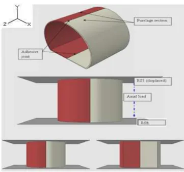
The proposed model consisted of two deformable parts for two fuselage sections, two adhesive layers, and two rigid surfaces as tools (RS1 and RS2). Fuselage sections are bonded with the zero thickness adhesive layers along the fuselage edge. The fuselage sections and adhesive are modelled as deformable parts that can deform under load. Tools are modelled as discrete rigid part (RS1) because they were considered much stiffer than the fuselage section.
2
Orthotropic woven C-glass fiber/epoxy 200 g/m2 [908].
RS1 is assumed to be rigid and is used in contact analyses to model bodies that cannot deform. Figure 9 shows the arrangement of the components. RS1 is displaced 80 mm downward at Z-direction to crash toward the fuselage section bonded with adhesive joint; RS2 is fixed to hold in a position during axial loading. The crushing responses from initial compression loading to final failure under geometrically nonlinear deformations are observed. The load-displacement data is compared with the experimental test.
Figure 8. Sketch of the deformable fuselage section.
Figure 9. Component arrangement.
All physical structures are nonlinear because the structure’s stiffness changes as it deforms. The crushing characteristic's fuselage can be explained by their load-displacement curves (Mahdi et al., 2006). In finite element modelling, a finer mesh typically results in a more accurate solution. However, as a mesh is made finer, the computation time increases. To determine the best modelling approach to get satisfactorily balances’ accuracy and computing resources, an attempt has been made at a mesh convergence study (Table 1). Mesh convergence is studied for mesh sizes 3, 5, and 8 mm. The agreement of the FEA with experimental results suggests that the mesh used is adequate to predict the overall response accurately. Mesh size of 3 mm will be used in the modelling because it is finer and more accurate and realistic to capture the deformation modes of the structure under compression loading. Figure 10 shows the mesh used for the fuselage sections and solid cohesive element.
Table 1. Convergence study by using different mesh sizes.
Mesh Size(mm) Mesh Elements Peak Load (kN)
3 11138 78
5 8316 76
8 3444 81
Figure 10. Fuselage sections and solid cohesive meshing.
FEA Results
The numerical result obtained by using ABAQUS/Explicit with the cohesive elements for the deformation modes and load-displacement is shown in Fig. 11 and Fig. 12.
Figure 11. Load-displacement diagram from FEA model.
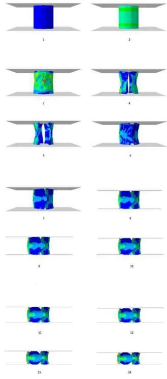
Figure 12. Collapse modes from FEA model.
At the beginning of the loading process, the applied load increases linearly up to the point 2, where the maximum load is reached, which is 78 kN at 2.4 mm displacement. After that, the experimental displacement curve and the numerical load-displacement curve drop off sharply to point 4. At point 4, debonding was observed between the fuselage sections during compression of 5.2 mm. The collapse modes (numbers) at each stage are shown in Figs. 11 and 12.
Quasi-Static Crushing Test
J. of the Braz. Soc. of Mech. Sci. & Eng. Copyright 2012 by ABCM January-March 2012, Vol. XXXIV, No. 1 / 73
moveable head a controlled velocity of 10 mm/min with respect to the stationary head. The load-sensing device was capable of indicating the total load being carried by the test specimen. Figure 13 shows the arrangement of the fuselage section on the testing area. Specimen was tested under axial compression loading until failure. The purpose of this test is to validate the proposed FEA model.
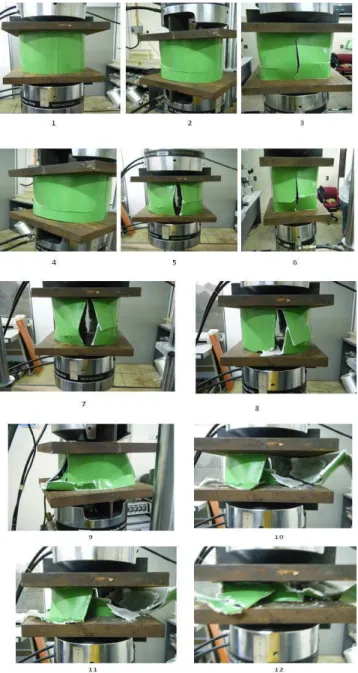
Figure 13. Quasi-static testing using MTS machine with deformation photos of test case.
From the test results, the load and displacement data were captured and tabulated. The load-deformation response along with its corresponding deformation photos for the composite fuselage section specimen under quasi-static lateral compressive load is shown in Fig. 14. The load increases linearly until it reaches the maximum load of 77 kN at approximately 3.79 mm deformation. As the crushing load increases the fuselage begins to buckle and the walls of the fuselage section start to bend. Fracture lines are developed at the right and left of the fuselage section as the load
reaches the maximum load. This failure is associated with the matrix micro-cracking failure and fracture of fibre-matrix bond.
FEA Validation
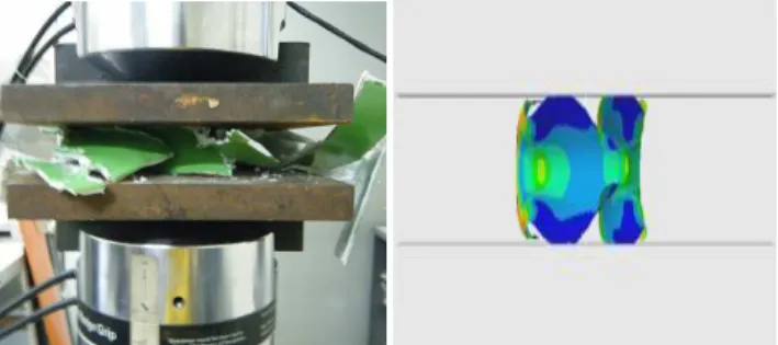
The agreement between the experiment and numerical results is good throughout the loading process (Figs. 14 and 15). The trend during crushing loading for both experiment and numerical is very similar. At the beginning of the loading process, the applied load increases linearly up to the point where the load maximum is reached. After that, the experimental load-displacement curve and the numerical load-displacement curve drop off sharply at approximately the same displacement.
For visual comparison of the peak load value attained by the experiment and the numerical analysis, the peak load for the experiment specimen is 77 kN and 78 kN for numerical results. The error in percentage of the peak load between the experiment and the failure theories used to simulate the progressive damage is found to be 1%. The collapse modes and crushing behaviour for both experiment and numerical results are found correlated (Table 2).
Figure 14. Load-displacement diagram experimental test vs. FEA results.
Table 2. Discrepancy (%) between FEA and experimental (test case 1) peak load.
Test Peak load (kN) Displacement (mm)
FEA simulation 78 2.4
Experiment test
case 1 77 3.79
Discrepancy (%) 1 37
Conclusion
In this research, a novel fabrication of a miniature composite fuselage structure (C-glass fiber/epoxy 200 g/m2 [90]8) is
• Finite element analysis using ABAQUS/Explicit is able to reproduce satisfactorily the load-deflection response that was observed in the series of the experimental works.
• Finite element simulation results pertaining to the main crushing characteristics (i.e. peak load and crush energy absorption) were very close to the experimental results.
• A reliable FEA model to predict the adhesive joint fabrication miniature composite fuselage structure under compression was successfully developed.
• Adhesive joint was successfully modelled by using cohesive element to predict adhesive behaviour and strength.
In view of the information obtained from the problems encountered throughout this research, it can be mentioned the imperfections such as a geometric imperfection which may be included in the finite element code in order to reduce errors and get better finite element results. It can be noted that effects of interlaminar could be included to investigate the progressive failure on the composite structure in future work.
Figure 15. Collapse modes for experimental test vs. FEA results.
Acknowledgement
The authors would like to thank to University Putra Malaysia for providing the research grant (FRGS 02-10-10-926FR 5524003) for this research work.
References
Bisagni, C., 2005, "Dynamic Buckling of Fiber Composite Shells under Impulsive Axial Compression", Thin-walled structures,43(3), pp. 499-514.
Chamis, C.C., Abumeri, G.H., 2005, "Probabilistic Dynamic Buckling of Composite Shell Structures". Composites Part A: Applied Science and
Manufacturing,36(10), pp. 1368-1380.
Dahdi.I.Edi, Y., Mustapha, F., Zahari, R., 2009, "Novel Fabrication for Tubular and Frusto Conical Composite Product for Aerospace Application" Conferences Proceeding of Aerotech Iii Kuala lumpur.
Goyal, V.K., Johnson, E.R., 2008, "Predictive Strength-Fracture Model for Composite Bonded Joints". Composite Structures,82(3), pp. 434-446.
Haji Yidris, N., Mokhtar, A.M., 2007, "Crush Simulation and Experimental Validation of a Composite Unmmaned Aerial Vehicle Fuselage Section", Universiti Putra Malaysia, pp. 1-161.
Koussios, S., Bergsma, O., Beukers, A., 2004, "Filament Winding. Part 1: Determination of the Wound Body Related Parameters". Composites Part
A: Applied Science and Manufacturing, 35(2), pp. 181-195.
Mahdi, E., Mokhtar, A., Asari, N., Elfaki, F., Abdullah, E., 2006, "Nonlinear Finite Element Analysis of Axially Crushed Cotton Fibre Composite Corrugated Tubes". Composite structures, 75(1-4), pp. 39-48.
Mahdi, E., Sahari, B., Hamouda, A., Khalid, Y., 2001, "An Experimental Investigation into Crushing Behaviour of Filament-Wound Laminated Cone-Cone Intersection Composite Shell", Composite structures, 51(3), pp. 211-219.
Mamalis, A., Manolakos, D., Ioannidis, M., Papapostolou, D., 2006, "The Static and Dynamic Axial Collapse of Cfrp Square Tubes: Finite Element Modelling", Composite structures,74(2), 213-225.
Morthorst, M., Horst, P., 2006, "Crushing of Conical Composites Shells: A Numerical Analysis of the Governing Factors". Aerospace science and technology,10(2), pp. 127-135.
Tafreshi, A., 2004, "Efficient Modelling of Delamination Buckling in Composite Cylindrical Shells under Axial Compression", Composite structures,64(3-4), pp. 511-520.
Tafreshi, A., 2006, "Delamination Buckling and Postbuckling in Composite Cylindrical Shells under Combined Axial Compression and External Pressure", Composite structures,72(4), pp. 401-418.
Tarfaoui, M., Gning, P., Hamitouche, L., 2008, "Dynamic Response and Damage Modeling of Glass/Epoxy Tubular Structures: Numerical Investigation", Composites Part A: Applied Science and Manufacturing, 39(1), pp. 1-12.
Vaziri, A., 2007, "On the Buckling of Cracked Composite Cylindrical Shells under Axial Compression", Composite structures,80(1), 152-158.
Xiao, X., McGregor, C., Vaziri, R., Poursartip, A., 2009, "Progress in Braided Composite Tube Crush Simulation", International Journal of Impact Engineering,36(5), pp. 711-719.
Yang, Z., Su, X., Chen, J., Liu, G., 2009, "Monte Carlo Simulation of Complex Cohesive Fracture in Random Heterogeneous Quasi-Brittle Materials", International Journal of Solids and Structures, 46(17), pp. 3222-3234.
Zarei, H., Krِger, M., Albertsen, H., 2008, "An Experimental and Numerical Crashworthiness Investigation of Thermoplastic Composite Crash Boxes". Composite structures,85(3), pp. 245-257.