Optimization of a Fuzzy Logic Controller for MR Dampers
Using an Adaptive Neuro-Fuzzy Procedure
Manuel Braz-César* Polytechnic Institute of Braganca
Department of Applied Mechanics, Braganca, Portugal
LESE–Laboratory for Earthquake and Structural Engineering Faculty of Engineering of the University of Porto Department of Civil Engineering, Porto, Portugal
brazcesar@ipb.pt; brazcesar@fe.up.pt
Rui Barros
Faculty of Engineering of the University of Porto and LESE–Laboratory for Earthquake and Structural Engineering
Department of Civil Engineering, Porto, Portugal
rcb@fe.up.pt
Received 12 March 2016 Accepted 21 August 2016 Published 9 December 2016
Intelligent and adaptive control systems are naturally suitable to deal with dynamic un-certain systems with non-smooth nonlinearities; they constitute an important advantage over conventional control approaches. This control technology can be used to design powerful and robust controllers for complex vibration engineering problems such as vibration control of civil structures. Fuzzy logic based controllers are simple and robust systems that are rapidly becoming a viable alternative for classical controllers. Furthermore, new control devices such as magnetorheological (MR) dampers have been widely studied for structural control applications. In this paper, we design a semi-active fuzzy controller for MR dampers using an adaptive neuro-fuzzy inference system (ANFIS). The objective is to verify the e®ectiveness of a neuro-fuzzy controller in reducing the response of a building structure equipped with a MR damper operating in passive and semi-active control modes. The un-controlled and un-controlled responses are compared to assess the performance of the fuzzy logic based controller.
Keywords: Structural control; MR damper; fuzzy logic control; ANFIS.
*Corresponding author.
Vol. 17, No. 5 (2017) 1740007 (18 pages) #
.
c World Scienti¯c Publishing Company DOI:10.1142/S0219455417400077Int. J. Str. Stab. Dyn. 2017.17. Downloaded from www.worldscientific.com
1. Introduction
Soft computing techniques have been shown to be e®ective in dealing with complex and nonlinear behavior of structural control systems. Fuzzy logic controllers can closely imitate human reasoning and control procedures enabling the use of previous experience and experimental results in designing simple and model-free control systems. The main problem relies on the optimization of the fuzzy parameters, in particular the de¯nition of a truthful inference system. In this regard, neuro-adaptive learning techniques such as ANFIS constitute simple methodologies to optimize fuzzy systems. This allows learning information about a dataset in order to compute the membership function parameters that best allow the associated fuzzy inference system to track a given input/output data. ANFIS is a hybrid learning algorithm that combines the backpropagation gradient descent and least squares methods to create a fuzzy inference system whose membership functions are iteratively adjusted according to a given set of input and output data. The reasoning scheme of ANFIS architecture and its inherent variables are shown in Fig.1, see Refs.1 and2. The inherent advantages of these neuro-fuzzy systems make them particularly suitable to develop control systems for structural engineering problems, which typically have uncertain parameters and nonlinear behavior. Besides, fuzzy based controllers allow a model-free estimation of the system and the fuzzy controller can be developed by encoding the knowledge of the system without the need to state how the outputs depend mathematically upon the inputs.
Fig. 1. The scheme of adaptive neuro-fuzzy inference system or ANFIS (see Refs.1and2).
Int. J. Str. Stab. Dyn. 2017.17. Downloaded from www.worldscientific.com
This paper describes the development of a fuzzy logic-based controller designed to reduce seismic-induced vibrations in a three degrees-of-freedom (3-DOFs) structural system representing a three-storey shear building structure by using a MR damper. These semi-active devices represent a promising technology with great potential for structural control applications. However, they present a highly nonlinear hysteretic behavior that needs to be considered in designing the control system. The design process of fuzzy controllers requires the characterization of several parameters (inputs, output, membership functions and the corresponding universe of discourse) and the de¯nition of inference rules that relates the inputs to obtain the desired output. This last operation can be carried out using only previous human knowledge about the system behavior or optimization techniques. However, inference rules of complex and/or nonlinear systems cannot be conveniently modeled by simple human knowledge demanding the use of optimization tools to obtain the relationship be-tween the inputs and output for a given problem.1,2This problem is addressed in this study in which ANFIS is used to optimize a set of fuzzy rules to design a fuzzy based controller to mitigate the vibration of a structural system.3,4 The optimization procedure with ANFIS is discussed in the development of the controller. The semi-active control system is derived from the data obtained with an optimal controller, which is used as a reference to train a fuzzy based controller via ANFIS. The un-controlled response is compared with passive and semi-active un-controlled responses in order to assess the performance of the proposed fuzzy controller. This paper is based upon Braz-Cesar and Barros,5but this previous paper has been enhanced including additional information about ANFIS model, a more detailed characterization of the response obtained with the passive control modes, the inclusion of new performance criteria to better evaluate the e®ectivness of the proposed fuzzy controller, and also references have been extended and updated.
2. Numerical Model
An e®ective semi-active control system involves an appropriate control algorithm that can take advantage of the dissipative properties of the control device, i.e. the MR damper.6,7There are several approaches available in the literature to control semi-active devices including soft computing techniques such as neuro-fuzzy con-trollers. Thus, a numerical analysis was carried out to evaluate the performance of a semi-active neuro-fuzzy controller in reducing the response of a simple structural system. The numerical model represents a three degrees-of-freedom system under seismic excitation as shown in Fig.2. A control force generated by an actuator (such as a MR damper) located between the base and the ¯rst mass, can be applied in order to reduce the system response. The damping force can be adjusted using a control system that based upon the system response computes the required damping force that should be applied to the system changes the system response in order to improve and control the structural performance.
Int. J. Str. Stab. Dyn. 2017.17. Downloaded from www.worldscientific.com
The parameters of the 3-DOFs system are as follows: m1= m2=m3¼100 kg;
c1¼125 Ns/m,c2=c3¼50 Ns/m;k1=k2=k3¼6105N/m. According to the
re-presentation depicted in Fig.2, the structural system can be described by means of the following matrices:
M¼
m1 0 0
0 m2 0
0 0 m3
2
4
3
5; ð2:1Þ
C¼
c1þc2 c2 0
c2 c2þc3 c3
0 c3 c3
2
4
3
5; ð2:2Þ
K¼
k1þk2 k2 0
k2 k2þk3 k3
0 k3 k3
2
4
3
5; ð2:3Þ
whereMis the mass matrix,Cis the damping matrix andKis the sti®ness matrix of the system. The natural frequencies and the corresponding mode shapes (inside brackets) are:freq1¼5:48 Hz ( 0.328, 0.591, 0.737),freq2¼15:37 Hz ( 0.737,
0.328, 0.591) andfreq3 ¼22:21 Hz ( 0.591, 0.737, 0.328). The equations of motion
of the controlled structure can be de¯ned by a state space formulation given by
z:ðtÞ ¼AzðtÞ þBfðtÞ þEx€gðtÞ; ð2:4Þ
wherez(t)¼ ½xðtÞ;x:ðtÞis the state vector,Ais the system matrix de¯ned by
A¼ 0 I
M 1K M 1C
: ð2:5Þ
B is an additional matrix accounting for the position of the control forces in the structure,f(t) is the control force,E is the disturbance vector andx€gðtÞrepresents
the seismic excitation loading. In this case there is only one control force applied to the ¯rst mass and then
B¼0 M 1¡T; ð2:6Þ
Fig. 2. Structural system controlled with a MR damper at the ¯rst °oor.
Int. J. Str. Stab. Dyn. 2017.17. Downloaded from www.worldscientific.com
where¡¼ ½1;0;0is the location vector. The earthquake excitation in°uence vector is de¯ned by
E¼½0 ¤T ð2:7Þ
in which ¤¼ ½1;1;1 represents the location of the external loading. The system response can be determined using the state space output vector de¯ned as
^
yðtÞ ¼Czð^ tÞ þD^fðtÞ þF^x€gðtÞ: ð2:8Þ
If the system displacements, velocities and accelerations are required, then
^
C¼
I 0
0 I
M 1K M 1C
2
4
3
5; ð2:9Þ
^
D¼½0 T; ð2:10Þ
^
F¼½0 ¸T; ð2:11Þ
whereĈis the output matrix,D^ is the feedthrough vector related with the control
force and F^ is the disturbance signal location vector. In this case,¼ ½1;0;0 and ¸¼ ½1;1;1represent the location of the control force and of the earthquake
accel-eration excitations at each °oor level, respectively.
The N-S component of the El-Centro ground motion (1940, peak acceleration of 3:42 m/s2) will be used as the excitation signal. The system represents a small-scale building structure and the earthquake signal was also scaled to characterize the magnitude of displacements that would be observed in experiments tests. In this case, the time was scaled to 20% of the full-scale earthquake time history as displayed in Fig.3.
The response of the structure can be controlled using a MR damper located between the ground and the ¯rst °oor. A small-scale MR damper based on the RD-1005-03 prototype (Lord Corp., USA) is used in this study. The device has a
Fig. 3. Time-scaled El-Centro NS earthquake excitation (0.2t).
Int. J. Str. Stab. Dyn. 2017.17. Downloaded from www.worldscientific.com
conventional cylindrical con¯guration with 41.4 mm in diameter, 208 mm long in its extended position allowing a stroke of 25 mm. The device can operate within a current range from 0.0 A up to 2.0 A with a usual value of 1.0 A for continuous operation. This MR damper can generate a peak force of 2224 N (1.0 A) using a small battery with less than 10 W. The device will be numerically modelled using the so-called modi¯ed Bouc–Wen model,8,9which is a usual phenomenological model to simulate the hysteretic behavior of this type of semi-active actuators. The me-chanical con¯guration of the modi¯ed Bouc–Wen model is shown in Fig.4.
Thus, the predicted damper force FMR can be obtained from the schematic
representation of the modi¯ed Bouc–Wen model (see Ref.8) depicted in Fig. 4by
FMR¼c01y_þk10ðx x0Þ; ð2:12Þ
in which
_
y ¼ 1
ðc0 0þc01Þ
½sþc00x_þk00ðx yÞ ð2:13Þ
is dependent on the evolutionary variable
_
s¼ jxjsjxjðn 1Þ x_snþx_: ð2:14Þ
Generally,,c00 andc01 are current dependent parameters described by
ðiÞ ¼aþbi; ð2:15Þ
c00ðiÞ ¼c00aþc00bi; ð2:16Þ
c01ðiÞ ¼c01aþc01bi; ð2:17Þ
whereiis the operating current. The parameters of the modi¯ed Bouc–Wen model are given in Table1.9The dynamics involved in the MR °uid reaching equilibrium state is represented through ¯rst order ¯lter given by
u: ¼ðu iÞ ð2:18Þ
in which the applied currentuis described with a time delay relative to the desired currentiand is the ¯lter constant (in this case,¼130 s 1).
Fig. 4. Phenomenological model of the MR damper (modi¯ed Bouc–Wen model).
Int. J. Str. Stab. Dyn. 2017.17. Downloaded from www.worldscientific.com
Using the state space formulation, the uncontrolled response of the 3-DOFs system under the earthquake ground motion is displayed in Fig.5. It should be noted that the response was obtained with a high excitation level of the El Centro earth-quake achieved by scaling up the amplitude of the earthearth-quake signal in 150%.
Table 1. Modi¯ed Bouc–Wen model parameters (RD-1005-3 MR damper) (see Ref.9).
Parameters [−] [mm 1] [mm 1] k00[N/mm] f0[N] n
Constant 10.013 3.044 0.103 1.121 40 2
ðiÞ ¼ 826:67i3þ905:14i2þ412:52iþ38:24 [N] Current dependent c00ðiÞ ¼ 11:73i3þ10:51i2þ11:02iþ0:59 [Ns/mm]
c0
1ðiÞ ¼ 54:40i3þ57:032þ64:57iþ4:73 [Ns/mm]
Fig. 5. Uncontrolled responses of the 3-DOFs system.
Int. J. Str. Stab. Dyn. 2017.17. Downloaded from www.worldscientific.com
3. Optimization of a Fuzzy Based Controller Using ANFIS
The fuzzy logic based controller was designed using ANFIS to ¯nd the nonlinear map that best ¯ts the expected response of the control system. The development of a neuro-fuzzy based controller typically involves four main steps:
(i) De¯nition of input variables and the corresponding fuzzy inference system (FIS) membership functions (the FIS output is the desired control signal);
(ii) Selection of data sets to generate training and checking data;
(iii) Use of ANFIS optimization algorithm for training the FIS membership function parameters to model the set of input/output data by mapping the relationship between inputs and outputs in order to generate a fuzzy model of the systems; (iv) Validation of the resulting fuzzy model.
ANFIS training procedure is summarized in the °owchart shown in Fig.6. The process begins by obtaining a training data set and checking data sets. The training data is used to ¯nd the premise parameters for the membership functions (MFs are dependent on the system designer). A threshold value for the error between the actual and desired output is determined. The consequent parameters are found using the least-squares method. If this error is larger than the threshold value, then the premise parameters are updated using the gradient decent method. The process ends when the error becomes less than the threshold value. Checking data set can then be used to compare the model with the actual system.
The data sets for training and validation can be obtained from numerical and experimental data. Usually, numerical training data provide better results in opti-mizing the fuzzy inference system since experimental results can have sparse or incomplete making the optimization procedure more di±cult. In this case, the
Fig. 6. Flowchart of ANFIS training.
Int. J. Str. Stab. Dyn. 2017.17. Downloaded from www.worldscientific.com
neuro-fuzzy controller was developed based on the numerical results of a linear quadratic Gaussian (LQG) controller whose response is used to de¯ne the training data set for the neuro-fuzzy optimization procedure with ANFIS. Floors accelera-tions and the displacement across the MR damper are the responses of the controlled system used by the LQG controller to determine the desired control force. The control signal is determined from the predicted control force using an inverse Bingham model of the MR damper. The system responses and the desired control signal were recorded and then used to train the neuro-fuzzy controller. Thus, the data sets for training and validation were obtained from a LQG controlled system to a set of amplitude-scaled versions of the El Centro NS earthquake excitation (i.e. 100 gal, 200 gal, 335 gal and 500 gal seismic accelerations). The LQG controller combines a linear quadratic regulator (LQR) algorithm with a Kalman ¯lter estimator. Identically distributed Gaussian white noise is used to simulate acceleration noise measurements. Regarding the LQR controller, the state gain matrix G is tuned through the weighting matricesQ andR. In the present example di®erent con¯g-urations of these parameters were evaluated by measuring the e®ect of each com-bination in the system response. The following weighting parameters provided the best performance in reducing in the structural response
Q¼ K 0
0 0
; ð3:1Þ
R¼r¼5e 7: ð3:2Þ
The observer gain L must be adjusted to achieve the required performance. A high gain allows the ¯lter to follow the observations more closely while a low gain follows the predictions more closely. This is accomplished by setting
Q!¼q!Ie; ð3:3Þ
Rv¼rvIm; ð3:4Þ
whereq!andrvare weighing factors, andIeandImare identity matrices related with the number of excitation inputs and measurement signals, respectively. A common approach is to set one of the tuning parameters and adjust the other parameter until the result is satisfying. In this caseIe ¼1ð€xgÞandIm¼I4X4ðx;€x1;x€2;x€3Þ.
The recorded velocity and the control signal from the LQG controller were used to de¯ne the training data for the fuzzy controller. The ¯rst and third °oor velocities are the FIS inputs while the current represents the fuzzy output. The choice of the ¯rst °oor velocity as input variable occurs since the MR damper was placed there on a non-collocated con¯guration. It is known that in general, viscous type damping is dependent on relative velocity. The third °oor velocity was chosen as input variable because of being the one that, according to the vibration mode shapes, will have the highest in°uence on the system response. Such two input variables were chosen to represent the dependence of the input current, because of the easiness of human visualization and interpretation of the controlled output signal through the use of
Int. J. Str. Stab. Dyn. 2017.17. Downloaded from www.worldscientific.com
three-dimensional surfaces. This obviously simpli¯es the proposed fuzzy controller approach.
An initial, increasing and decreasing step sizes of 0.12, 1.20 and 0.8, respectively during 200 epochs are the optimization parameters. The optimal number of mem-bership functions (MFs) was de¯ned through a trial-and-error process. In this case, six bell-shaped MFs were used to model each input variable (¯rst and third °oor velocities). The resultant fuzzy surface is shown in Fig.7.
When the ¯rst and third °oor velocities are large and have the same signs, the required control signal is also large. When both velocities are large but have opposite signs, the fuzzy controller delivers the lowest control signal. Besides, the minimum damping force requirement is located around the central zone comprising small °oor velocities.
4. Numerical Results
The MR damper can operate in two modes: as a passive energy dissipation device, i.e. without a control system (the properties of the actuator are constant during the simulation) and as a semi-active actuator whose control action is being commanded by a neuro-fuzzy based controller. A set of numerical simulations was carried out to obtain the response of the three DOF structure using the MR damper in a passive OFF mode (zero voltage/current input), passive ON mode (maximum value of the operating current) and semi-active control mode. The results of the a neuro-fuzzy semi-active control system are compared with the uncontrolled, passive OFF and passive ON responses to evaluate the e±ciency of the semi-active control scheme in reducing the structural response. A Simulink model of the semi-active control system is shown in Fig.8.
A new numerical simulation was carried out to obtain the responses of the structure for the passive OFF and passive ON modes with the MR damper
Fig. 7. Fuzzy surface of the neuro-fuzzy controller.
Int. J. Str. Stab. Dyn. 2017.17. Downloaded from www.worldscientific.com
represented by the modi¯ed Bouc–Wen model. The system response for the passive OFF case along with the uncontrolled response of the 3rd °oor is shown in Fig.9.
The corresponding force-velocity and force-displacement responses, i.e. damping force plots for the passive OFF con¯guration (passive energy dissipation with i¼ 0:00 A) are shown in Fig.10. Likewise, the system response achieved with the passive ON con¯guration (passive energy dissipation with i¼0:50 A) along with the un-controlled response is shown in Fig.11. The corresponding velocity and force-displacement responses for this control mode is shown in Fig.12.
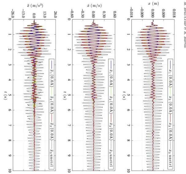
The results show a considerable vibration reduction using the MR damper as a passive energy dissipation device in a passive ON con¯guration. The increase of the operating current in the MR damper has a signi¯cant e®ect in the damping force and the energy dissipation capacity of the device. Figure13 displays the structural re-sponse of each °oor obtained with the proposed fuzzy based control system along with the uncontrolled response of the third °oor during the numerical simulation. As can be seen, the proposed semi-active control system achieves a good performance in reducing the structural responses using only °oor velocities as the reference (input) signals to compute the control action. In fact, the main advantage of this fuzzy logic based control system is that only the ¯rst and third °oor velocities of the structure are required to determine the desired control signal. This means that the damping
Fig. 8. Simulink model of the semi-active control system.
Int. J. Str. Stab. Dyn. 2017.17. Downloaded from www.worldscientific.com
Fig.
9.
Structural
response
with
a
passive
OFF
control
mode.
Fig.
10.
MR
damper
force
in
a
passive
OFF
control
con¯gur
ation.
M.
Braz-C
e
sar
&
R.
Barros
1740007
-12
Fig. 11. Structural response with a passive ON control mode.
Fig. 12. MR damper force in a passive ON control con¯guration.
Int. J. Str. Stab. Dyn. 2017.17. Downloaded from www.worldscientific.com
force generated during the control process does not need to be monitored, as happens in other controllers such as the clipped-optimal algorithm.
The damper force and the control signal of the semi-active control system are shown in Fig.14. As can be seen, the proposed fuzzy controller provides intermediate levels of control current instead of the bi-state control signal used in many semi-active controllers allowing intermediate damping states over the full range of oper-ation of the device. Generally, the results show that the proposed fuzzy logic con-troller is capable to determine with su±cient reliability the required control action to reduce the response of the 3-DOFs system.
The hysteretic behavior of the MR damper during the numerical simulation is also characterized in Fig.15. As can be seen the proposed fuzzy based controller explores the operating range of the actuator and globally, the hysteretic loops are in line with
Fig. 13. Structural response with the fuzzy logic controller.
Int. J. Str. Stab. Dyn. 2017.17. Downloaded from www.worldscientific.com
those found with the other controllers although in this case presenting a more irregular shape.
The main drawback of designing fuzzy controllers is related with the de¯nition of the membership function parameters and the inference rules that relate the inputs with the desired control output. Structural systems usually include several sources of nonlinearities and/or uncertainties that hinder the development of simple control rules based on human knowledge about the system behavior. In these cases, soft computing techniques such as ANFIS or genetic algorithms (GAs) are most
Fig. 14. Damper force and corresponding operating current (semi-active control).
Fig. 15. MR damper force in a semi-active control mode (see specs in Sec.2).
Int. J. Str. Stab. Dyn. 2017.17. Downloaded from www.worldscientific.com
appropriate to ¯nd the best set of fuzzy rules or adjustment of a set of fuzzy parameters in accordance with a given training data for a desired control action.
5. Performance Evaluation
The evaluation criteria are based on a comparison of the peak responses of each controlled system to those of the uncontrolled system and passive modes. The results
Table 2. Peak responses—El-CentroNS earthquake (0.2t).
Control strategy x(cm) x_(cm/s) x€(cm/s2) Drift (cm) f(N)
0.695 27.09 1305 0.695
Uncontrolled 1.251 45.78 1736 0.581 —
1.587 54.02 2272 0.371
0.518 (0.75) 20.02 (0.74) 999 (0.77) 0.518 (0.75)
Passive OFF 0.907 (0.73) 34.51 (0.75) 1358 (0.78) 0.443 (0.76) 166.4 1.191 (0.75) 42.79 (0.79) 1791 (0.97) 0.292 (0.79)
0.171 (0.25) 7.77 (0.29) 613 (0.47) 0.171 (0.24)
Passive ON 0.423 (0.34) 19.36 (0.42) 1066 (0.61) 0.253 (0.44) 1048.9 0.560 (0.35) 25.58 (0.47) 1366 (0.60) 0.208 (0.56)
0.164 (0.24) 7.07 (0.26) 739 (0.57) 0.164 (0.24)
ANFIS-FLC 0.410 (0.33) 17.59 (0.38) 963 (0.55) 0.247 (0.43) 909.8 0.529 (0.33) 23.64 (0.44) 1285 (0.57) 0.194 (0.52)
Table 3. Evaluation criteria for the controlled system.
Evaluation criteria Description
J1¼max
t;i xicðtÞ xmax;uðtÞ
Maximum peak °oor displacement ratio whereby the °oor displacements over time are normalized by the maximum peak uncontrolled displacement.
J2¼max
t;i _
xicðtÞ _
xmax;uðtÞ
Maximum peak °oor velocity ratio whereby the °oor velocities over time are normalized by the maximum peak uncontrolled velocity. J3¼max
t;i €
xicðtÞ €
xmax;uðtÞ
Maximum peak °oor acceleration ratio whereby the °oor accelerations over time are normalized by the maximum peak uncontrolled acceleration.
J4¼max
t;i jjxicðtÞjj
jjxmax;uðtÞjj
Maximum RMS °oor displacement ratio given in terms of the maximum RMS absolute displacement over time with respect to the uncontrolled case.
J5¼max
t;i jjx_icðtÞjj
jjx_max;uðtÞjj
Maximum RMS °oor velocity ratio given in terms of the maximum RMS absolute velocity over time with respect to the uncontrolled case.
J6¼max
t;i jj€xicðtÞjj
jj€xmax;uðtÞjj
Maximum RMS °oor acceleration ratio given in terms of the maximum RMS absolute acceleration over time with respect to the uncontrolled case.
J7¼max
t;j P
jPjðtÞ xmax;uW
Maximum control power normalized by (x_maxW), i.e., the weight of the
structure times the maximum uncontrolled velocity.Wis the total weight of the structure.
J8¼max
t;j P
j Rtf
0 1
tfPjðtÞ xmax;uW
!
Total power required to control the response of the structure normalized by the weight of the structure times the maximum uncontrolled velocity.
Int. J. Str. Stab. Dyn. 2017.17. Downloaded from www.worldscientific.com
of this analysis are summarized in Table2. The results show the e®ectiveness of the proposed fuzzy based controller in reducing the response of the structure. In this case the fuzzy controller outperforms the passive control modes in almost all peak responses (with exception of the ¯rst °oor acceleration, although with a signi¯cant reduction compared with the uncontrolled case). The results also show that using the MR damper in a semi-active control mode results in lower peak drifts compared with the passive ON con¯guration namely in the two upper °oors.
A new set of evaluation criteria was used to evaluate the e®ectiveness of each control mode.10,11These evaluation criteria are given in Table3, including normal-ized and RMS responses and also control requirements.12The ¯rst three criteria (J
1,
J2,J3) are based on the peak responses and the next four (J4,J5,J6) are related with
RMS (normed) structural responses. In these equations, j j denotes the absolute value andjj jjis theL2 norm given by
jj jj ¼
ffiffiffiffiffiffiffiffiffiffiffiffiffiffiffiffiffiffiffiffiffiffiffiffiffi
1
tf
Z tf
0
½2dt
s
; ð5:1Þ
wheretf ¼tmax represent the total excitation duration. The last three performance indices (J7,J8) are intended to evaluate the e®ectiveness of the MR actuator. The
results achieved with each control mode are presented in Table4.
From the results presented in Tables3and4, it can be concluded that the semi-active fuzzy controller in a comprehensive way outperforms the passive control con¯gurations (note that lower values indicate a better performance). Note that the performance indicesJ1toJ6are related with the structural responses, and re°ect the
higher e±ciency of the proposed semi-active control system over the passive control modes. In fact, the performance indices are consistent with the results reported in the peak responses analysis.
6. Conclusion
This paper addressed the optimization of a fuzzy based controller using an ANFIS. This modeling approach was used to develop a neuro-fuzzy model for a MR damper based on arti¯cial training data. A numerical simulation was used to obtain and analyze the e®ectiveness of the proposed semi-active controller in reducing the re-sponse of a simple structural system. It was veri¯ed that the semi-active controller
Table 4. Evaluation criteria for each control con¯guration.
Control mode J1 J2 J3 J4 J5 J6 J7 J8
Passive OFF 0.750 0.371 0.789 0.487 0.495 0.507 0.021 0.0014 112% 158% 31% 192% 140% 77% 59% 0% Passive ON 0.353 0.144 0.602 0.167 0.206 0.287 0.051 0.0014
ANFIS–FLC 0.334 0.131 0.566 0.164 0.192 0.261 0.035 0.0014
5% 9% 6% 2% 7% 9% 31% 0%
Int. J. Str. Stab. Dyn. 2017.17. Downloaded from www.worldscientific.com
allowed a more e±cient management of the actuator displaying a better performance in reducing the structural response than the passive control modes. Hence, it can be concluded that the proposed semi-active fuzzy based control system outperforms a fully passive system allowing a considerable reduction of lateral motion of the masses using only a MR damper in a non-collocated control con¯guration. Further research must be carried out to improve the fuzzy optimization procedure using ANFIS and also to validate the application of neuro-fuzzy controllers to a wide range of struc-tural con¯gurations.
References
1. J. R. Jang, ANFIS: Adaptive-network-based fuzzy inference system,IEEE Trans. Syst. Man. Cybern.23(3) (1993) 665–685.
2. A. R. Sadeghian, Nonlinear neuro-fuzzy prediction: Methodology, design and applications fuzzy systems,10th IEEE Int. Conf. Fuzzy Syst.(2) (2001) 1022–1026.
3. K. C. Schurter and P. N. Roschke, Neuro-fuzzy control of structures using acceleration feedback,Smart Mater. Struct.(10) (2001) 770–779.
4. H. S. Kim, P. N. Roschke, P. Y. Lin and C. H. Loh, Neuro-fuzzy model of hybrid semi-active base isolation system with FPS bearings and a MR damper, Eng. Struct.28(7) (2006) 947–958.
5. M. Braz-Cesar and R. Barros, Neuro-fuzzy control of structures with MR dampers,13th Conf. Dynamical Systems Theory and Applications DSTA 2015, Dynamical Systems: Control and Stability, Vol. 3 (2015), pp. 95–106.
6. S. J. Dyke and B. F. Spencer, A comparison of semi-active control strategies for the MR damper,Proc. IASTED Int. Conf., Intelligent Information Systems(1997), pp. 580–584. 7. L. M. Jansen and S. J. Dyke, Semi-active control strategies for MR dampers:
Compar-ative study,J. Eng. Mech., ASCE125(8) (2000) 795–803.
8. B. F. Spencer Jr., S. J. Dyke, M. K. Sain and J. D. Carlson, Phenomenological model of a magnetorheological damper,J. Eng. Mech. ASCE(123) (1997) 230–238.
9. M. Braz-Cesar and R. Barros, Experimental and numerical analysis of MR dampers,
COMPDYN 2013 –4th International Conference on Computational Methods in Struc-tural Dynamics and Earthquake Engineering(2013).
10. B. F. Spencer, S. J. Dyke and H. S. Deoskar, Benchmark problems in structural control: Part I active mass driver system,Earthquake Eng. Struct.(27) (1998) 1127–1139. 11. B. F. Spencer, S. J. Dyke and H. S. Deoskar, Benchmark problems in structural control:
Part IIactive tendon system,Earthquake Eng. Struct.(27) (1998) 1141–1147.
12. Y. Ohtori, R. Christenson, B. Jr. Spencer and S. Dyke, Benchmark control problems for seismically excited nonlinear buildings,J. Eng. Mech., ASCE(10) (2004) 1061.
Int. J. Str. Stab. Dyn. 2017.17. Downloaded from www.worldscientific.com