ISSN 1517-7076
Revista Matéria, v. 12, n. 3, pp. 487 – 493, 2007 http://www.materia.coppe.ufrj.br/sarra/artigos/artigo10887
Synthesis of TiC thin films by CVD from toluene and titanium
tetrachloride with nickel as catalyst
López-Romero, S.I; Chávez-Ramírez, J.IIIInstituto de Investigaciones en Materiales. Universidad Nacional Autónoma de México Circuito Exterior s/n Ciudad Universitaria A. Postal 70-360 Coyoacán C.P. 04510 México D.F. México Tel. 00 52 55 5622 4732 Fax. 00 52 55 5616 1251
e-mail: [email protected]
IIFacultad de Química. Universidad Nacional Autónoma de México Circuito Exterior s/n Ciudad Universitaria A. Postal 70-360 Coyoacán C.P. 04510 México D.F. México Tel. 00 52 55 5622 4732 Fax. 00 52 55 5616 1251
e-mail: [email protected]
ABSTRACT
Titanium Carbide TiCx was deposited onto quartz substrates by the chemical vapour deposition (CVD) method. TiCx thin films were obtained from titanium tetrachloride (TiCl4) and toluene (C6H5CH3) as carbon source. Deposits were carried out in the range of substrate temperatures from 300 to 1100 C, with a source gas molar ratio (C6H5CH3/TiCl4 + C6H5CH3 ) of 0.8. There was two deposit processes; the first was to carry out without nickel as catalyst and the second with nickel as catalyst.
Results showed that the effect of nickel as catalyst is very relevant to obtain TiCx. TiC0.87 thin films, 0.5 m thickness, were obtained for deposition temperatures above 900C using nickel as catalyst. In this case a cubic structure, with a lattice parameter of 4.327 Å and a hardness of 2900 Vickers, was obtained at 11000C. whilst for substrate temperatures between 300 to 900°C with nickel as catalyst amorphous carbon samples were obtained. For the samples prepared without the presence of the nickel as catalyst only C amorphous thin films were obtained for all deposit temperatures.
Keywords: Titanium carbides, CVD, nickel catalyst, cubic structure, lattice parameter, microhardness.
1 INTRODUCTION
Carbon and elements from the group IV form the transition metal carbides. From this group TiCx, which assumes the NaCl crystal structure fcc, is a typical example [1]. TiCx has a wide range of composition, from TiC0.47 to TiC1.0, where the complement 1–x corresponds to vacancies. Titanium carbide, TiC, is known as one of the hardest carbides with a hardness of 1900 kg/mm2 [2] at TiC0.8. Since it possesses a remarkable thermal and chemical stabilities, its melting temperature is 3067 ºC and it is not affected by acids or aqueous
alkalis [3], titanium carbide is therefore of great industrial interest, i.e. as first-wall coating for fusion reactors and coating for tools and bearings [4, 5, 6, 7, 8]. TiC also can be used as decorative thin films [9] There are several techniques to prepare titanium carbide coatings such as ion plating (IP), sputtering, plasma enjanced chemical vapour deposition (PECVD) [10], reactive ion beam-assisted electron beam –physical vapor deposition (RIBA, EB-PVD) [11], by laser igniting self-propagating high-temperature synthesis LISHS [12], by self—propagating high-temperature synthesis SHS [13]. Thermal CVD technique has shown to be an effective mean to obtain TiC high purity and defect free films [14, 15, 16].
Commercial processes involve chemical vapour deposition from hydrogen, methane and titanium tetrachloride at 1200 ºC [17].In this work TiCx films were deposited on silica quartz by thermal CVD with
2 EXPERIMENTAL
The experimental system was a typical hot–wall reactor, figure 1. The reactor chamber consisted of a horizontal silica tube, 100 cm length and 2 cm diameter, placed into a furnace. TiCl4 (l) (99.99%) and C6H5CH3 (l) (99.99%) were used as source reactant materials and helium as carrier gas. TiCl4 (g) was introduced into the silica tube by bubbling 200 sccm of helium (99.99%) through a glass flask of TiCl4 (l) at 80 ºC. The C6H5CH3 (g) was introduced into the silica tube by bubbling 40 sccm of helium (99.99%)
through a glass flask of C6H5CH3 (l) under a temperature of 30 ºC. The molar ratio of the reactants TiCl4 (g)
and C6H5CH3 (g), mc = [C6H5CH3/ (TiCl4 + C6H5CH3 )], was 0.8. Nickel, which was used as catalyst, was
placed in 1 cm2 area sheets alternating with the quartz substrates, figure 1. Deposition temperatures (TDEP) ranged from 300 C to 1100 C, with a deposition time of 45 min. Under similar conditions, deposits were carried out with and without nickel as catalyst. For crystalline samples, preferred orientation and lattice parameters were investigated by X–ray diffraction (XRD) using a Siemens D 500 diffractometer, CuKα radiation with = 1.5406 Å. The thickness of the films was measured with a Dektak IIA equipment. The stoichiometry of the samples was determined by EDS with a Pentafet microprobe linked to a Leica–
Cambridge Stereoscan 440 electron microscope. Microhardness measurements on the deposits were carried out with a Matsuzawa Seiki MXT30-UL ultra microhardness tester equipped with a Knoop indenter, suitable for measurement of extremely thin plates that are hard to be measured by the ordinary Vickers hardness testers. The deposition rate was calculated from a linear relationship between the thickness of deposits and deposition time.
Figure 1: Schematic diagram of the CVD apparatus: 1) He (g), 2) valve, 3) flow meter, 4) TiCl4 reservoir,
5) C6H5CH3 reservoir, 6) constant temperature bath, 7) ribbon heater, 8) horizontal silica tube and 9) furnace.
3 RESULTS AND DISCUSSION
3.1 Nickel as Catalyst
Nickel belongs to a transition metals family in which the elements are very efficient catalysts. Ni is widely used in the laboratory and industry in a umber of liquid–phase and gas–phase processes involving organic compounds [18]. Transition elements are distinguished of main group elements having partly filled d or f shells. The main transition group, or d– block elements have partially filled the d shell [19]. Nickel metal ion has, on average, 9.4 valence shell orbitals [20], –s, px, py, pz, dz2, dx2
– y2, dxy, dxz, dyz– to accommodate its valence electrons to form hybrid molecular orbitals bonded to other groups [18]. These valence orbitals inherent to nickel metal give the capacity to form both sigma () and pi () bonds with other moieties or ligands. This is an ability to form those bonds, one of them is the key factor imparting catalytic properties to the nickel metal and its complexes [19].
In this work, the reaction between titanium tetrachloride and toluene to obtain titanium carbide may be described as
7 TiCl4 + C6H5CH3 + Ni (catalyst) 7 TiC + 8 HCl + 10 Cl2 (1)
The presence of HCl and gas chloride as reaction products were detected by conventional methods, however it is necessary to carry out a detailed study about the kinetic of the reaction to elucidate the role of the nickel as catalyst in this process. This work is in progress.
3.2 Structure and Film Composition
3.2.1 Without nickel
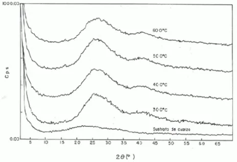
X–ray diffraction patterns of TiC thin films deposited on fused quartz substrates of 1 cm2, at different temperatures, 300 ºC to 600ºC, without the nickel presence, are shown in figure 2. These patterns
showed only broad curves, characteristic of graphitic amorphous carbon..
Figure 2: X-ray diffractograms pattern of the amorphous carbon thin films
prepared at differents temperatures without nickel as catalyst.
Figure 3 shows the X–ray diffraction patterns of TiC films, which were deposited at substrate temperatures of 700 ºC to 1100ºC without nickel as catalist. This patterns also showed the amorphous
character of the TiC films.
Figure 3: XRD analysis of the amorphous carbon thin films prepared at
3.2.2 With nickel
Figures 4 and 5 shows the X-ray diffractograms of the TiC films prepared at 300-6000C,
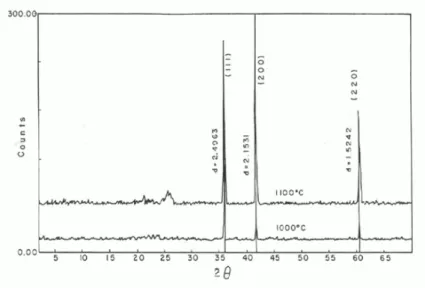
700-9000C temperature intervals’s with nickel as catalyst respectively, it is clearly observed that this TiC films are amorphous. X–ray diffraction patterns of the samples prepared at, 1000 and 1100 ºC, using nickel as catalyst during the deposit process, are showed in figure 6. XRD patterns exhibited intense peaks at 35.94, 42.71 and 60.45 2 degrees, for the two deposition temperatures. These strong reflections are associated to the fcc structure of the TiC phase [21]. The lattice parameter a of TiC was calculated from the d spacing using the most intense peaks. Results indicated that these carbides are cubic with a cell parameter a = 4.3270 Å, which matches well the standard JCPDS 6–1614, also similar to the value a = 4.3285 Å which was reported for the bulk standard [2], this a value is also consistent to that reported by Norton and Lewis [20].
Figure 4: X-ray diffractograms of amorphous carbon thin films prepared
at differents temperatures with nickel as catalyst.
Figure 5: X-Ray diffractograms of amorphous carbon thin films prepared
Figure 6: X-Ray diffractograms of TiC thin films prepared at 1000 and 11000C with nickel as catalyst.
The composition ratio x (x =C/Ti) obtained by EDS resulted to be approximately the same value for the two deposit temperatures, x = 0.87. This result is consistent with the study realized by Guinier [21 on TiC obtained by ARE; however these authors concluded that for high values of the molar fraction ( > 0.7) x and a are independent of deposition temperature, in this temperature range.
The crystallite size, which were estimated from the full width at half maximum peak using the Scherrer equation [22, was 230 nm.
3.3 Microhardness
With the use of the indenter Knoop it is possible to measure an indentation length min. of 0.01microm or 100nm. We have TiC films with thickness > 500nm, for that reason, we can be sure that the hardness measurements are of the TiC thin films. For the hardness measurements a load of 50g was used.
The microhardness of TiC film shows a marked dependence on the substrate temperature. Microhardness results of the crystalline TiC films which were deposited in the range temperature 1000°C–
1100ºC are summarized in Table 1.
Table 1: Microhardness for crystalline TiC films as a function of the substrate temperature.
Substrate Temperature (º C) Microhardness (50 g load) (Vickers)
1000 2500
1 100 2900
These results are similar to those which were reported by Bunshah´s group on ARE deposited films [21, 23.
4 CONCLUSIONS
Thermal CVD of toluene and titanium tetrachloride were carried out at deposition temperature range 300 –1100 ºC on quartz substrates using helium as carrier gas.
Deposits were obtained with and without nickel as catalyst. Below 900 ºC, X–ray diffraction revealed that the films prepared with nickel as catalyst are of amorphous carbon, whilst those films deposited betwen 300 to 1100 ºC without nickel as catalyst all exhibited amorphous carbon.
5 ACKNOWLEDGEMENTS
We would like to thank L. Baños and J. Guzmán for their technical assistance.
6 BIBLIOGRAPHY
[1 CADOFF, Y., NIELSEN, J.P., ―Synthesis of TiC by Arc.Melting‖, Journal of Metals, v. 5, pp. 248-256, 1953.
[2 STORMS, E.K., ―The refractory carbides‖, v. 2, New York, USA, Academic Press, 1967.
[3 WILLIAMS, W.S., ―Transition-Metals Carbides‖, Progress in Solid-State Chemistry, v. 6, pp. 57-118, Jan 1971
[4 SCHAWARZKOP, P., KIEFFERR, P., LESZYNSKY, W., BENESOVSKY, F., Refractory hard metals, New York, USA, Macmillan, 1953.
[5 TOTH, L.E., Transition metal carbides and nitrides, New York, USA, Academic Press, 1971.
[6] KURISHITA, H., AMANO, Y., KOBAYASHY, S., et al, ―Development of ultra-fine grained W-TiC and
their mechanical properties for fusion applications‖, Journal of nuclear Materials, v. 367-370, pp.
1453-1457, 2007.
[7] GUO, J., BIN-SHI, X., HAI-DOU, W., et al, ―Investigation on the formation and wear resistance of TiC
coatings‖, Materials Science and Engineering A., v. 435-436, pp. 355-359, July 2006.
[8] RAZAVI, M., RAHIMIPPOUR, M., HOSSEIN, A., et al, ―Effect of nanocrystaline TiC pouder addition
on the hardness and wear ressistance of cast iron‖, Materials Science and Engineering A., v.
454-455, pp. 144-147, 2007.
[9] FERNANDEZ, A.C., VAZ, F., CUNJA, L., et al, ―The influence of structure changes in the properties of TicxOy decorative thin films‖, Thin Solid Films, v. 515, pp. 5424-5429, 2007.
[10 HINTERMANN, H.E., GASS, H., SCHEWEIZ, H.A., ―Organometalic route to the chemical vapour deposition of the titanium carbide films‖, Angew. Wiss. Tech., v. 33, pp. 3-10, 1967.
[11] WOLFE, D.E., SING, J., ―Titanium carbide coatings deposited by reactive ion bean-assisted, electron bean-physical vapour deposition‖, Surface and Coating Technology, v. 124, pp. 142-153, 2000. [12] LI, Y.X., HU, J.D., WANG, H.Y., et al, ―Thermodinamic and lattice parameter calculations of TiC x
produced from Al-Ti- C powders by laser igniting self-propagating high-temperature synthesis‖, Materials Science and Engineering A., v. 458, pp. 235-239, 2007.
[13] COCHEPIN, B., GAUHTIER, V., VREL, D., et al, ―Cristal growth of TiC grains during SHS
reactions‖, Journal of Crystal Growth, v. 304, pp. 481-486, 2007.
[14] CAO, L.X., FENG, Z.C., LIANG, Y., et al, ―Thin films of TiC by CVD‖, Thin Solid Films, v. 257, pp. 7-14, 1995.
[15] SHI, R., MENG, W.J., EVANS, R. P., ―Characterization of high temperature deposited Ti-containing
hydrogenated carbon thin films‖, Journal Applied Physics II, v. 96, pp. 7705-7709, 2004.
[16] KONYASIN, I.Y., ―Thin TiCx films chemically vapour deposited onto cemented carbides from TiCl4-CCl4-H2 mixture‖, Thin Solid Films, v. 278, pp. 37-44, 1996.
[17 LEE, M., RICHMAN, M.H., ―Chemical vapour deposition of a TiC coating cemented-carbide cutting
[19 RANDHAWA, H., ―Cathodic plasma deposition of TiC and TiCxN1-x films‖, Thin Solid Films, v. 153, pp. 209-218, 1987.
[20 NORTON, J.T., LEWIS, R.K., Advanced Metals Research Corp, pp. N63-18389, Somerville, Massachusetts, 1963.
[21 GUINIER, A., Theore et technique of the radiocristalographie Dunod, Paris, 1964.
[22 RAGHURAM, A.C., BUNSHAH, R.F., WAGNER, C.N.J., ―Structure and relationships in Ti, Zr. Ans Hf-3Zr carbide deposits , synthesized by activated reactive evaporation‖, Thin Solid Films, v. 20, pp. 187-192, 1974.
[23 JACOBSON, B.E., BUNSHAH, R.F., ―Transmission electron microscopy of TiC and WC_TiC deposits