S
C
I
E
N
T
I
F
I
C
-T
E
C
H
N
I
C
A
L
Influence of flow pattern development at die entrance and
inside annular die on extrudate swell
behavior of NR compound
Naret Intawong
1*, Sittichai Udomsom
1, Konnatee Sugtakchan
1and Watcharin Sitticharoen
11
Department of Industrial Engineering, Faculty of Engineering, Rajamangala University of
Technology Lanna, 128 Huay Kaew Road, Chiang Mai, 50300, Thailand
Abstract
This research studies inluence of the low pattern at annular die entrance through the inside of annular die low channel of capillary rheometer on the swell behavior of NR compound. The annular die used in this research was speciically designed to create the speciic pattern of Vortex Flow at Die Entrance (VFE) of NR compound. Results of the study showed that the thickness swell ratio was higher than diameter swell ratio by an average of 20% at every die gap size. It was also found that the VFE low pattern had direct signiicant inluence on the swell behavior of NR compound while extrudating through annular die. Results from the study of the low pattern could be used to explain why the thickness swell ratio is higher than the diameter swell ratio in every test condition.
Keywords: capillary rheometer, annular die, diameter swell ratio, thickness swell ratio, NR compound.
1. Introduction
In polymer extrusion process, a device called annular die is used for most shaping of polymer products, such as in pipe extrusion process, extrusion blow moulding process, and blow film extrusion process. It is widely known that, for melt polymer extrudated through annular die, the size of polymer parison will expand both in diameter and thickness dimensions[1]. This is an important variable that production
engineers must pay attention to, in order to control quality and size of polymer products. The products’ expansions in two dimensions are called diameter swell ratio and thickness swell ratio, respectively. In general, this occurrence could be explained in terms of elastic recovery and resident time, and the complex flow occurrences, due to the design of annular die[2,3].
Evidences from existing research show that important variable that influences the swell behavior of melt polymer after extrudated from the die is, in fact, the complex flow pattern of melt polymer at the die entrance which, in turn, resulting from the die design. Song et al.[4] studied the flow
patterns of NR, SBR and EPDM in a barrel of capillary rheometer, using a wide range of die designs. They found that the radial flow simply moved inward to the capillary die as the ram moved down the barrel. So, no secondary flows occurred. Wood et al.[5] studied the flow pattern of natural
rubber compound in different types of capillary rheometer, using colored layer technique. The experimental results show that velocity profiles and flow pattern are important variables in determining the flow properties of polymer. Eggen and Hinrichsen[6] had investigated the effect of die
entrance angle and die length on extrudate swell and the onset of extrudate distortion in capillary extrusion. They found that the elongation component at the entrance region mainly influenced the extrudate distortion. Sombatsompop and Dangtungee[7,8] both studied the effect of die/barrel system
design on flow visualization and die swell of NR in a capillary rheometer, using colored layer technique. They found that the amount of natural rubber compound’s swell was influenced by pressure drop and complex flow pattern at the die entrance. In the most recent study of Intawong et al.[9],
they studied the flow pattern and extrudate swell properties of Natural Rubber (NR) compound in a capillary rheometer, using two types of annular die: convergent annular die and divergent annular die. Their experimental results show that the thickness swell was higher than the diameter swell in every test condition. This difference could be explained by analysis of the complex flow pattern at the die entrance.
All the research mentioned above show the application of knowledge from studies about the development of flow pattern in melt polymer to explain the swell property of melt polymer while extrudating through the die. However, all these research are limited only to the development of flow pattern inside the barrel. Therefore, this research presents a continuing study from the research of Intawong et al.[9],
by applying its results to demonstrate a direct influence of Vortex Flow at Die Entrance, which further develops into the die’s flow channel, on the swell behavior of melt polymer while extrudating through annular die, especially on the thickness swell ratio.
2. Experimental
2.1 Materials
All of the tests used natural rubber (NR: STR 5L), supplied from PAN INNOVATION LIMITED (Thailand). The materials were compounded in accordance with experimental procedure from the previous work of Intawong et al.[9].
pigmented NR compound (white color of NR+ Titanium Oxide compound) and unpigmented NR compound (brown color of NR compound).
2.2 Experimental technique and apparatus
The experimental technique used for the study of the flow pattern of extrudated NR compound was colored layer technique. Details of the technique had already been published in the previous work of Intawong et al.[9], which reported
an interesting result that the development of Vortex Flow at Die Entrance (VFE) had direct influence on the swell behavior of NR compound after extrudating through annular die. In order to get more insight into this occurrence, this research presents a new design of annular die that creates only the VFE flow pattern in the flow system. It also shows an obvious development of the flow pattern at the entrance through the flow channel of annular die. Results of the study could explain effect of VFE on the flow properties and the swell behavior of NR compound, without interference from the Vortex Flow at Wall (VFW) flow pattern. Details of the design in Figure 1 show that the annular die consists of 3 main parts: Die body #1, mandrel, and Die body #2, respectively. Figure 1a shows that Die body #1 has an outer diameter of 36mm, with 4 holes of 14.5mm diameter for flow channel of melt polymer. Moreover, the top part of Die body #1 also has an annex (extended part) called a “Simulated obstructions” that features a cylindrical shape with 10 mm diameter and 6 mm height. This simulated obstruction is important in being a determiner and controller of NR compound’s flow direction to create the VFE flow pattern before going through flow channels of the annular die. It simulates flow condition of melt polymer flowing through a mandrel in a real production process. The mandrel part is designed to be centrally assembled to the bottom of Die body #1. Its diameter (a) could be changed to 2mm, 3mm, and 4mm, respectively. Both Die body #1 and mandrel are assembled with Die body #2 which has an outer diameter of 40mm and a constant flow channel of 6mm in diameter and 65mm in length. Thus, there are die gaps of 1mm, 1.5mm, and 2mm, respectively. Figure 1b shows a cross-section of annular die
that is assembled to a split barrel of the capillary rheometer, where the annular die is centrally fixed at the bottom of the barrel with a Die holder. In addition, a pressure transducer (Dynisco, Model PT460E-2CB-6, Franklin, MA)[10,11] is also
installed on the 5mm top of the die entrance, in order to measure die entrance pressure drop, which will be further used to study the rheological properties.
2.3 Measurement of flow properties
The wall shear stress (τW) and the apparent wall shear
rate (γw•) were determined using Equation 1 and Equation 2,
respectively[12].
2
ent w
H P L
∆
τ = (1)
(
1 2 2)
w n H
•
γ = − + ν (2)
Where H = Die gap, ΔPENT = entrance pressure drop, L= Die land length, ν= average velocity, as defined by a piston speed of the capillary rheometer, and n = Power-law index. In this work, the apparent wall shear rates were varied from 1 s–1 to 2.5 s–1.
2.4 Measurements of extrudate swell ratio
The diameter swell ratio (BD) and the thickness swell ratio (BT) of NR compound were calculated from Equation 3 and Equation 4, respectively[13].
p D
o D B
D
= (3)
p T
o h B
h
= (4)
Where DP = parison’s diameter, DO = outside diameter of the annular die, hP = parison’s thickness, and hO = die gap of the annular die.
3. Results and Discussion
3.1 Flow pattern development in the barrel
Figure 2a-c shows development of the flow pattern of NR compound occurred inside the barrel of capillary rheometer in a form of Axial Flow (AF)[9,14], at the piston extrudate rates
of 25mm to 100mm with 1.5 s–1 apparent wall shear rate.
This resulted from using a die with die gaps of 1mm, 1.5mm, and 2mm, respectively. It was found that the development of Axial Flow pattern showed continuous development of the melt layer velocity throughout all extrudate rates. In general, there are shear flow pattern and parabolic-like
pattern with low melt velocity at the wall, and the highest velocity at the center of the barrel. These experimental results correspond with results from the previous study of Intawong et al.[9], as expected.
Regarding the effect of die gap size on the development of Axial Flow pattern of NR compound, it was found that reduction of the die gap size made the AF melt velocity increased significantly. This was confirmed by experimental results that counted number of NR compound layer with the AF flow left in the barrel of each die gap size, as shown in Figure 3. Results indicated that the number of NR compound layer linearly decreased continuously when the extrudate rate was increased in every die gap size. At the same extrudate rate, it was found that the number of NR compound layer left in the barrel decreased with the decrease of die gap size. This implied that the melt velocity of NR compound in the barrel increased as well. For instance, at the extrudate rate of 50mm, the number of NR layer decreased from 10 to 9 and 8 layers when the die gap size reduced from 2mm to 1.5mm and 1mm, respectively. That is, it increased by an average of 5% for every 0.5mm reduction of die gap size. This implied that the AF melt velocity of NR compound increased by 5% for every 0.5mm reduction of die gap size as well.
This resulted from the effect of adjusting balance of volumetric flow rate while the NR compound flew into the annular die channel, as could be explained by Equation 5[15].
Q=vA (5)
Where A is a cross-sectional area of annular die channel, v is an average velocity of NR compound, and Q is a volumetric flow rate of NR compound.
It can be seen that the size of die gap is reduced by decreasing the cross-sectional area of annular die channel (A) while the total volumetric flow rate of NR compound after extrudating from the die remains the same, due to a constant extrusion rate or apparent wall shear rate. Therefore, the NR compound flowing through the barrel into the annular die channel is accelerated (v), in order to adjust the balance of Volumetric flow rate to remain constant[16].
Figure 2. Flow patterns of NR compound in the barrels of capillary
rheometer with different piston displacements [25mm, 50mm, 75mm and 100mm] and shear rate of 1.5 s–1. (a) die gap = 1mm;
(b) die gap = 1.5mm; and (c) die gap = 2mm.
Figure 3. Number of NR compound layer left in the barrel of
3.2 Flow pattern development in annular die
This section describes an analysis of the Radial Flow (RF) flow pattern at the die entrance which occurred after the AF mentioned above. This will provide more insight into the development of flow pattern from the barrel into the annular die channel. This will also lead to a clearer explanation of the swell behavior of melt polymer flowing through the annular die. Figure 4a-c shows the flow pattern development of NR compound while flowing from the barrel into the annular die channel, which are selected from
experimental results at the shear rate of 1.5 s–1, die gap of
2mm, and the extrudate rate of 50mm to 75mm. The flow pattern development of NR compound was detected by tracking the movement of Layer A, Layer B and Layer C from the barrel into the annular die, respectively.
In Figure 4a, Layer A is shown in a brown line at the top of the layer, which is developing its flow pattern from AF to RF. Layer B shown in a white line below begins to flow into the annular die channel along the surface of artificial blockage in a form of VFE. Both ends of this rubber layer begin to enter into the center of the annular die channel. Layer C which is the final flow layer of NR Compound is shown in a brown line flowing completely into the annular die channel. Development of the flow pattern occurs continuously with the extrudate rate, as shown in Figure 4b. Layer A begins to enter the annular die channel while Layer B begins to replace Layer C, as can be seen that all the NR layers inside the annular die channel change from brown to white. In the final stage of flow pattern development in Figure 4c, Layer A replaces Layer B completely again, as can be seen that all the NR Compound inside the annular die channel changes from white to brown.
The flow pattern mentioned above develops continuously while the NR compound was extrudated through the annular die, and the molecular chain of NR compound was aligned (molecular orientations) in the same direction as the flow. The important occurrence throughout the flow is, while there is replacement between layers, every layer is forced to flow along the surface of both simulate obstructions at the top and the mandrel, which is a very long distance. As a result, there is more stretching of molecular chain of NR compound at the inner layer than at the outer layer, as shown in Figure 5. Therefore, there is accumulation of elastic storage energy at the inner wall of NR compound layer. After exiting the annular die, the inner layer will become the wall of parison that will be influenced by an emission of elastic energy accumulated throughout the flow. As a result, the expansion in thickness is more pronounced than the expansion in diameter. This swell behavior is also found in this research and will be further explained in details.
Figure 4. (a) The first stage of flow pattern development of NR
compound Layer A, Layer B, and Layer C; (b) the replacement of Layer A to Layer B and Layer B to Layer C; (c) the final stage of flow pattern development by NR compound Layer A replaced by Layer B completely.
Figure 5. A schematic molecular orientations drawing of the
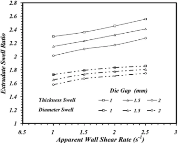
3.3 Extrudate swell ratio behavior of NR compound The flow pattern development of NR compound from the barrel into the annular die channel mentioned above has an obvious direct effect on the swell behavior of NR compound extrudated through annular die of every size, as shown in Figure 6. In general, it is found that the thickness swell and the diameter swell of NR compound increase with the increase of apparent shear rate in every test condition. This is because the increase of apparent shear rate is like the increase of force on NR compound while flowing into the annular die. This force occurs in a form of an apparent shear stress that increases with the increase of apparent shear rate, as shown in Figure 7. The increase of apparent shear stress indicates that there is increasing accumulation of elastic storage energy of NR compound while exiting the annular die. Thus, there is emission of energy which affects the swell of NR compound parison that increases in both dimensions.
When comparing the swell behavior of NR compound between the thickness swell ratio and the diameter swell, it
was found that the thickness swell ratio was higher than the diameter swell ratio in every test condition. This corresponds with the research finding[9] which found that the thickness
swell ratio of NR compound extrudated through every size of die gap was in a range of 2-2.5, while the diameter swell ratio was lower in a range of 1.6-1.9. In other words, it could be said that the thickness swell ratio was higher than the diameter swell ratio by about 20% in every size of die gap. This could be explained by the theory of accumulated elastic energy of NR compound while flowing in the annular die channel, together with evidences of the flow pattern development of NR compound described in the above section. That is, while flowing into the annular die channel, the molecular chain at the inner layer of NR compound (the part that will become the thickness of NR parison) tends to be stretched more than other layers. This can be seen from flow direction of the layer that is forced to flow along the surface of the simulate obstructions before entering the annular die channel, and it is stretched again at the mandrel’s surface. Consequently, this NR compound layer is forced by a shear stress more than other layers, and the force is also accumulated as elastic storage energy more than in other layers. Therefore, there is more emission of elastic energy at the inner layer of NR compound and, hence, more pronounced in the higher thickness swell ratio. This explanation may contradict with the Deborah number (Ndep) theory which is used to explain the swell behavior
of melt polymer in many other research[7,8]. This theory
explains that the longer resident time of polymer in extrudate system with a long flowing distance causes the occurrence of molecular relaxation which reduces the shear stress; thus, the swell ratio decreases after exiting the die. However, findings of this research indicate differently. In particular, the inner layer of NR compound that has longer flowing distance than other layers tends to have a higher swell ratio. With this finding, it is believed that the length of resident time do have certain effect on the swell behavior, but less than the influence of shear stress on the surfaces of simulate obstructions and mandrel. This explanation corresponds with the research of Mu et al.[17] who studied shear stress
distributions of melt polymer in annular die using FES/BPNN/ NSGA-II mathematical model and found that the shear stress distributed densely at the mandrel’s surface. The experimental result about the effect of die gap on both thickness and diameter swell behaviors of NR compound is another piece of evidences that supports the above explanation. It can be seen that both thickness swell and diameter swell of NR compound increase in relation to the decrease of die gap’s size. This especially affects the thickness swell ratio more than the diameter swell ratio. It is also found that, at the same apparent wall shear rate, the thickness swell tends to increase in relation to the decrease of die gap’s size. This is because the size of die gap is decreased by the increasing mandrel’s diameter (a), which also increases the surface area of mandrel. The increasing area of mandrel’s surface leads to the increase of shear stress on the molecular chain of NR compound’s inner layer. After exiting the annular die, the thickness swell is found to increase in relation to the decrease of die gap’s size. For example, at the apparent wall shear rate of 1.5 s–1, it was found that the thickness
swell ratio increased from 2.11 to 2.23 and 2.36, in relation
Figure 6. Diameter swell and thickness swell of NR compound
flowed from the annular die with different die gap of 1mm, 1.5mm and 2mm.
Figure 7. Flow curves of NR compound with the die gap of 1mm,
to the decrease of die gap from 2mm to 1.5mm and 1mm, respectively. In other words, the average increase is about 7% for every 0.5mm decrease of die gap at every apparent wall shear rate. On the other hand, the diameter swell ratio also tends to increase in relation to the decrease of die gap, but only at an average of 3% for every 0.5mm decrease of die gap, at every apparent wall shear rate. This is because the NR compound that will become the outer diameter of parison is the outside layer of the wall of annular die that seems to be influenced by less amount of shear stress. This is because the surface area of the outer diameter of annular die wall does not change from its constant outer diameter of 6mm in every test condition.
4. Conclusion
This research presents the study of the effects of the flow pattern of NR compound at the annular die entrance through the annular die flow channel on the swell behavior of NR compound in capillary rheometer. Results of the study explain the influence of the Vortex Flow at Die Entrance (VFE) flow pattern on the swell behavior of NR compound while extrudating through annular die, especially of the thickness swell ratio. That is, the thickness swell ratio is higher than the diameter swell ratio by an average of 20% in every die gap’s size. This could be explained from the fact that the VFE flow pattern at annular die entrance causes more stretching of the molecular chain and more accumulation of elastic storage energy at the NR’s inner layer, which will later become thickness of NR parison, than in the NR’s outer layer while flowing inside the annular die flow channel.
5. Acknowledgements
The authors would like to thank the “Upgrading Theses into Research Publications, Creation, and Academic Service for Community Project” (HRG: Hands-on Research Group) of Rajamangala University of Technology Lanna (RMUTL) for financial support throughout this work.
6. References
1. Cogswell, F. N. (1981). Polymer melt rheology. London:
George Godwin.
2. Garcia-Rejon, A., & Dealy, J. M. (1982). Swell of extrudate
from an annular die.Polymer Engineering and Science, 22(3),
158-165. http://dx.doi.org/10.1002/pen.760220305.
3. Wagner, A. H., & Kalyon, D. M. (1996). Parison formation
and inflation behavior of polyamide-6 during extrusion blow molding.Polymer Engineering and Science, 36(14), 1897-1906. http://dx.doi.org/10.1002/pen.10586.
4. Song, H. J., White, J. L., Min, K., Nakajima, N., & Weissert,
F. C. (1988). Rheological properties, extrudate swell, and die
entry extrusion flow marker experiments for rubber-carbon black compounds.Advances in Polymer Technology, 8(4),
431-449. http://dx.doi.org/10.1002/adv.1988.060080407. 5. Wood, A. K., Read, A. G., & Lovegrove, J. G. A. (1989). The
effects of rheometer design in the measurement of the flow properties of polymer melts.Plastics and Rubber Processing and Applications, 12(1), 15-20.
6. Eggen, S., & Hinrichsen, E. (1996). Swell and distortions of
high-density polyethylene extruded through capillary dies. Polymer Engineering and Science, 36(3), 410-424. http:// dx.doi.org/10.1002/pen.10428.
7. Sombatsompop, N., & Dangtungee, R. (2001). Effect of die
design on flow visualization and die swell of NR in a capillary rheometer.Journal of Materials Science Letters, 20(15), 1405-1408. http://dx.doi.org/10.1023/A:1011695527853. 8. Sombatsompop, N., & Dangtungee, R. (2001). Flow visualization
and extrudate swell of natural rubber in a capillary rheometer: effect of die/barrel system.Journal of Applied Polymer Science, 82(10), 2525-2533. http://dx.doi.org/10.1002/app.2103. 9. Intawong, N-T., Wiratket, A., & Meechue, P. (2014). Flow
visualization & extrudate swell behavior of natural rubber compound in annular die capillary rheometer. Polímeros: Ciência e Tecnologia, 24(4), 434-440. http://dx.doi.org/10.1590/0104-1428.1696.
10. Intawong, N.-T., Darajang, A., Udomsom, S., Yoochooshai, T., & Kantala, C. (2014). An annular rotating-die technique
in extrusion process: effect of mandrel rotating speed on entrance pressure drop and flow properties of molten HDPE. International Journal of Plastics Technology, 18(2), 241-251. http://dx.doi.org/10.1007/s12588-014-9080-1.
11. Intawong, N.-T., Wongchaleo, C., & Sombatsompop, N. (2008).
Rheological properties, flow visualization and extrudate swell of NR compound by rotating-die rheometer.Polymer Engineering and Science, 48(6), 1191-1198. http://dx.doi. org/10.1002/pen.21074.
12. Winter, H. H., & Fritz, H. G. (1986). Design of dies for the
extrusion of sheets and annular parisons: the distribution problem.Polymer Engineering and Science, 26(8), 543-553. http://dx.doi.org/10.1002/pen.760260805.
13. Koopmans, R. J. (1992). Extrudate swell of high density
polyethylene. Part III: extrusion blow molding die geometry effects.Polymer Engineering and Science, 32(23), 1755-1764.
http://dx.doi.org/10.1002/pen.760322304.
14. Intawong, N.-T., Kantala, C., Lotaisong, W., & Sombatsompop,
N. (2011). A die rotating system for moderations of extrusion
load and pressure drop profiles for molten PP and wood/ polypropylene composites in extrusion processes.Journal of Applied Polymer Science, 120(2), 1006-1016. http://dx.doi.
org/10.1002/app.33209.
15. Diraddo, R. W., & Garcia-Rejon, A. (1992). Noncontact
measurement of parison thickness profiles affected by swell and sag in continuous extrusion blow molding.Polymer Engineering and Science, 32(19), 1401-1410. http://dx.doi.
org/10.1002/pen.760321902.
16. Intawong, N.-T., Darajang, A., Udomsom, T., Yoochooshai,
S., & Kantala, C. (2014). An annular rotating-die technique in
extrusion process: effect of mandrel rotating speed on extrudate swell behavior of HDPE parison.International Polymer Processing, 29(5), 607-615. http://dx.doi.org/10.3139/217.2930. 17. Mu, Y., Zhao, G., Wu, X., & Zhang, C. (2010). An optimization
strategy for die design in the low-density polyethylene annular extrusion process based on FES/BPNN/NSGA-II.International Journal of Advanced Manufacturing Technology, 50(5-8), 517-532. http://dx.doi.org/10.1007/s00170-010-2556-z.

![Figure 2. Flow patterns of NR compound in the barrels of capillary rheometer with different piston displacements [25mm, 50mm, 75mm and 100mm] and shear rate of 1.5 s –1](https://thumb-eu.123doks.com/thumbv2/123dok_br/18869558.419745/3.765.385.691.760.1005/figure-patterns-compound-barrels-capillary-rheometer-different-displacements.webp)