Geometry and Kinematics of Experimental Antiformal Stacks
CAROLINE JANETTE SOUZA GOMES and JULIANO EFIGÊNIO FERREIRA
Departamento de Geologia, Universidade Federal de Ouro Preto 35400-000 Ouro Preto, Minas Gerais, Brasil
Manuscript received on July 16, 1999; accepted for publication on November 9, 1999; presented byIgor I. Gil Pacca
ABSTRACT
Sandbox experiments with different boundary conditions demonstrate that antiformal stacks result from a forward-breaking thrust sequence. An obstacle blocks forward thrust propagation and transfers the deforma-tion back to the hinterland in a previously formed true duplex. In the hinterland, continued shortening causes faults to merge toward the tectonic transport direction until the older thrusts override the younger thrusts. In experiments using thin sand layers or high basal friction, shortening is accommodated by a cyclic process of thrusting, back rotation of the newly formed thrust combined with strong vertical strain, and nucleation of a new thrust. Continuous deformation produces an antiformal stack through progressive convergence of branch lines.
key words:basement structures, slightly dipping basal detachment, sand layer thickness, basal friction.
INTRODUCTION
Physical modelling has been used with success to in-vestigate the mechanical and kinematic evolution of structures and deformational systems. For example, Daviset al. (1983) and Dahlenet al. (1984) have proposed the critical taper model based on math-ematical calculations and demonstrated its validity using sandbox modelling. Marshak et al. (1992) have discussed the formation of curved thrust belts using analogue models. McClay & Ellis (1987), McClay (1990) and McClay & Scott (1991) have presented scaled sandbox models of extensional structures to illustrate the tectonic evolution of sed-imentary basins.
Thrust system geometries were described by Ballyet al.(1966), Dahlstrom (1969) and Boyer & Elliott (1982). Boyer & Elliott (1982) published a
Correspondence to: Caroline Janette Souza Gomes E-mail: [email protected]
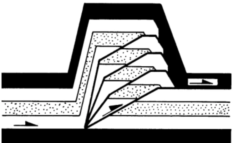
classification and an evolutionary tectonic model for these contractional sequence. Mitra (1986) intro-duced the concept of “overlapping ramp anticlines”, based on the amount of shortening accommodated by the thrust systems. Mitra’s classification dis-tinguishes a foreland sloping duplex, consisting of partly overlapping anticlines, from an anticli-nal stack, consisting of completely overlapping an-ticlines. McClay (1992) defined antiformal stacks as systems of totally overlapping thrust horses characterized by a coincident trailing branch line (Fig. 1).
struc-GEOMETRY AND KINEMATICS OF EXPERIMENTAL ANTIFORMAL STACKS 196
Fig. 1 – An antiformal stack according to McClay (1992).
ture formed consists of independent ramp anticlines separated by broad synclines”, and the ‘true du-plexes’, as “a particular combination of final thrust spacing, ramp angle and ramp height such that parts of all the link thrusts and roof thrusts are parallel to the frontal ramp of the duplex”. The character-istic feature of true duplexes is the presence of at least two branch lines: a trailing branch line and a leading branch line. In antiformal stacks, due to the increasing displacement of individual ramp anti-clines, those branch lines coincide (McClay, 1992). This study concerns the mechanical constraints that permit, in a primary built duplex, that trailing branch lines gather together before a new thrust arises in the foreland. In addition, it also investigates the process involved in thrust horses overriding one another.
Although anticlinal stacks have been described by many authors, no study on the mechanics control-ling their development has yet been conducted. For example, Jadoonet al.(1992) described antiformal stacks in a fold belt in Pakistan and attributed their formation to a detachment, having a 2.5◦slope (Fig.
2). Using a balanced cross-section, Muñoz (1992) presented a basement-involved antiformal stack in the axial zone of the Pyrenean continental collision belt (Fig. 3).
In this paper, we present a series of sandbox analogue experiments to investigate the evolution of antiformal stacks in a thrust system. The boundary conditions described by Jadoonet al. (1992) and
Muñoz (1992), i.e. a slightly dipping basal detach-ment and control by basedetach-ment structures, respec-tively, are also examined. We have introduced some variables concerning the geometry of pre-existing basement structures (herein, referred to as “obsta-cle”), initial sand layer thickness and basal friction. The study of the different obstacle geometries has the purpose of highlighting the kinematic evolution of antiformal stacks. The variations in layer thick-ness and in the degree of basal friction are to in-vestigate possible effects over the antiformal stack geometry.
Physical models permit direct observation of analogs for evolving geological structures. Thus, they may allow observation of structures and pro-cesses not yet recognized in nature. The correlation between models and nature presents some difficul-ties due to the insufficient knowledge on the complex rheologic properties of deforming rocks. Moreover, simulation of the earth’s crust in sandboxes requires the entire continental crust to be treated as a contin-uous medium with homogeneous properties. Thus, small-scale variations in the mechanical properties of rocks, compaction of sediments and thermal per-turbations cannot be considered. Even with those difficulties, simulations provide valuable insights into the development of thrust systems and, in par-ticular, of antiformal stacks, for which theoretical and experimental tectonic models are not available.
EXPERIMENTAL METHODS AND PROCEDURE
In our models, the brittle, upper continental crust was simulated using carefully sieved and dyed quartz sand (200-300µm) from the alluvial Ita-colomi Quartzite (Ouro Preto, Minas Gerais). Dry sand, widely used as an analogue for rocks from the upper continental crust, has an internal friction angle of 30◦and fails according to a Navier-Coulomb law.
GEOMETRY AND KINEMATICS OF EXPERIMENTAL ANTIFORMAL STACKS 197
Fig. 2 – An antiformal stack over a basement slope of 2.5◦and after shortening of 37%, in a balanced,
NNW-SSE geological cross-section from the frontal Sulaiman fold belt of the Himalayan Mountain system in central Pakistan (after Jadoonet al.1992).
Fig. 3 – A basement-involved antiformal stack in a balanced cross-section of the middle of the Pyrenean continental collision belt, after 39% shortening (Muñoz, 1992).
possible to their natural equivalents”, it is neces-sary to produce geometric, kinematic and dynamic similarities. In an elastic body, length strain is pro-portional to stress and is time independent. Thus, the most important model ratios to simulate brittle deformation are those concerning stress (strength) and length. These ratios are related by the equation:
σR=δ×λ(gm/go=1),
where
σR=σmodel/σoriginal,
the ratio between model and original strength,
δ=δmodel/δoriginal,
the ratio between model and original densities,
λ=λmodel/λoriginal,
the model ratio of length, and
gm/go, the ratio between model and original gravity acceleration.
The length ratioλ=10−5, used in the present
simulations (1 cm in the model corresponds to 1 km in the natural prototype), requires a reduction of 100,000 times in the model strength. Thus, dry sand with strength near zero constitutes an ideal brittle analogue material. Since brittle deformation is time independent (Vendevilleet al.1987), the shortening in our experiments was produced with a constant displacement rate of 2 cm hr−1.
GEOMETRY AND KINEMATICS OF EXPERIMENTAL ANTIFORMAL STACKS 198
TABLE I
Experimental details and figure numbers
Exp. Thickness of Length of Type of Type of Geometry of Detachment Total Figure No. initial sand initial sand backstop “obstacle” basal material shortening numbers
layer (cm) layer (cm) detachment (%)
M1-a 3.0 30.0 rigid wall high* horizontal plastic sheet 77 7
wooden block
M1-b 3.0 30.0 sand pack high* horizontal plastic sheet 68 8
wooden block
M2-a 3.0 30.0 rigid wall small* horizontal plastic sheet 80 9
wooden block
M2-b 3.0 30.0 sand pack small* horizontal plastic sheet 68 10
wooden block
M3-a 0.9 20.0 rigid wall fixed, horizontal plastic sheet 70 11 vertical end-wall
M3-b 0.9 10.0 sand pack fixed, horizontal plastic sheet 33 12
vertical end-wall
M4-a 3.0 28.0 rigid wall fixed, slightly tilted (5◦) plastic sheet 50 – vertical end-wall
M4-b 3.0 28.0 sand pack fixed, slightly tilted (5◦) plastic sheet 50 13
vertical end-wall
M5-a thickness decreases 32.0 rigid wall fixed, inclined wooden plastic sheet 56 14 from 3.0 to 1.0 vertical end-wall wedge
M5-b thickness decreases 32.0 sand pack fixed, inclined wooden plastic sheet 53 15 from 3.0 to 1.0 vertical end-wall wedge
M6 3.0 40.0 rigid wall fixed, horizontal sand paper 45 16
vertical end-wall
M7 thickness decreases 32.0 rigid wall fixed, inclined wooden sand paper 56 17 from 3.0 to 1.0 vertical end-wall wedge
∗wooden block is much higher than the initial sand layer ∗∗wooden block and initial sand layer have the same heights.
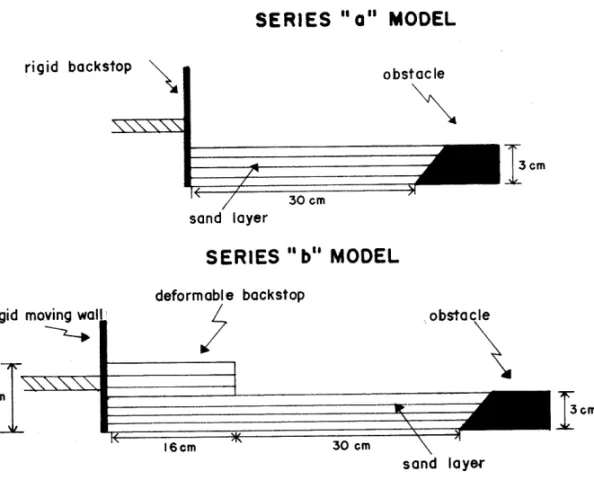
backstop of the deformation front (the “bulldozer” behind an accretionary wedge). As this material has a disproportionately large strength compared to the mechanical properties of the sand, we repeated some of the models using a deformable backstop. Thus, all series “a” models were deformed by a vertical rigid wall moving towards the foreland. In series “b” experiments, this moving wall was replaced by a sand pack, with mechanical properties similar to the rest of the model. All series “b” experiments still required a rigid moving wall connected to the motor, but this wall was located 16 cm behind the front of the sand pack (Fig. 4). The results show that a 16 cm-long deformable sand pack is sufficient to prevent any interference by the rigid wall with the geometry of the thrust wedges.
All models were deformed in a rectangular (60 cm × 20 cm × 15 cm), glass-sided, acrylic box
that permitted the continuous observation of defor-mation. The models were serially photographed
through the transparent sided wall. At the end of each experiment, the models were dissected and dif-ferent internal sections were photographed. Each model presented in this paper was repeated at least twice with similar results.
GEOMETRY AND KINEMATICS OF EXPERIMENTAL ANTIFORMAL STACKS 199
Fig. 4 – Sketches of the experimental boxes (models M2), illustrating the boundary conditions of series “a” and series “b” experiments.
are insignificant, however, and are assumed to be a result of minor irregularities in the sandbox and/or from manual handling of the analogue material. The drawings shown in Figures 7 to 17 were made from photographs taken during each model run, always on the same side wall.
All models were set up with a rigid obstacle in the foreland. The role of the obstacle was to block the evolution of a forward-breaking thrust sequence. In experiments M1 and M2, we introduced steeply dipping wooden blocks of different heights as ob-stacles. In experiments M3 to M7, the fixed, ver-tical end-wall of the sandbox serves this function. The aim of experiments M1 to M3 was to inves-tigate the geometry of contractional systems when the progressive movement of the deformational front was completely impeded (set M1 and M3) or only partially, since displacement over the obstacle was possible (set M2). The disproportionate height of the obstacle in M1 and M3 has no analog in nature,
and was set up only to achieve better understanding the role of an obstacle in the antiformal stack evo-lution. Model M3 is similar to model M1 in that displacement of the deformation front is completely obstructed, but was set up to examine the effect of different thicknesses on the antiformal stack evolu-tion.
In models M4-M7, additional factors were an-alyzed. In models M4 and M5, we investigated the antiformal stack formation over a slightly dipping basal detachment. Model M4 was performed simi-larly to M2-b but, prior to compression, the exper-imental box was tilted 5◦ towards the hinterland.
Model M5 was built above a wooden wedge tilted 5◦towards the hinterland. The sand layers were
de-posited horizontally.
GEOMETRY AND KINEMATICS OF EXPERIMENTAL ANTIFORMAL STACKS 200
(A)
(B)
(C)
GEOMETRY AND KINEMATICS OF EXPERIMENTAL ANTIFORMAL STACKS 201
Fig. 6 – Two opposite side wall sections of the same experiment (model M2-a), after 80% shortening, revealing slightly different geometries in the antiformal stack (see text). Scale bar is 5 cm.
effect of an increase in the basal friction. The base of the experimental box was covered with sand pa-per. Two situations were investigated: 1) a horizon-tal box (model M6), and 2) a box containing a 5◦
inclined wooden wedge at its base (model M7).
EXPERIMENTAL RESULTS
Models M1, M2and M3
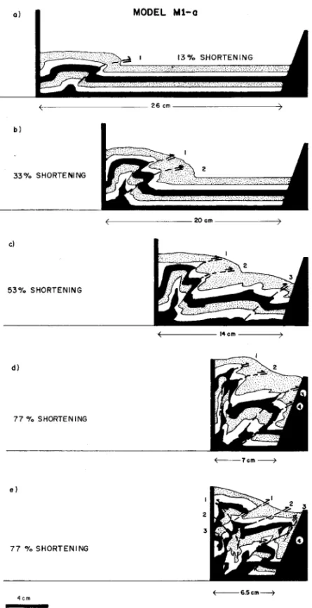
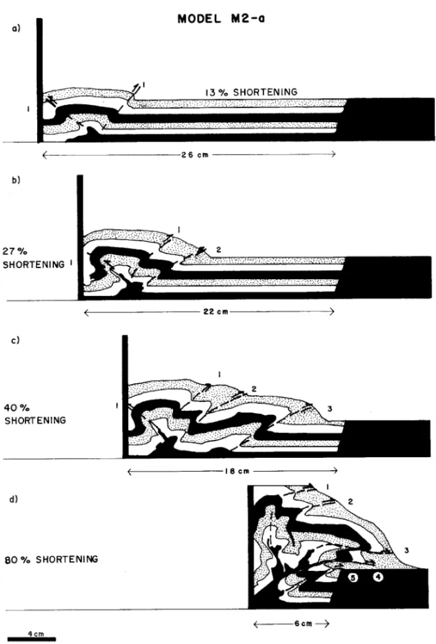
In experiments M1 and M2 (Figs. 7, 8, 9 and 10), two stages of deformation were recognized. The first stage consists of formation and growth of a true duplex in a forward-breaking sequence not
influ-enced by the obstacle. The thrust system forms by displacement of the sand layer over the basal tachment, thickening and forethrusting of the de-formation front, usually associated with a smaller backthrust. After faulting, the newly formed hang-ing wall is displaced over the thrust plane and the process is repeated. With the increasing mass of the thrust system, new faults in the foreland form farther from the older ones (Figs. 7c, 8b, 9c and 10c).
GEOMETRY AND KINEMATICS OF EXPERIMENTAL ANTIFORMAL STACKS 202
GEOMETRY AND KINEMATICS OF EXPERIMENTAL ANTIFORMAL STACKS 203
GEOMETRY AND KINEMATICS OF EXPERIMENTAL ANTIFORMAL STACKS 204
GEOMETRY AND KINEMATICS OF EXPERIMENTAL ANTIFORMAL STACKS 205
GEOMETRY AND KINEMATICS OF EXPERIMENTAL ANTIFORMAL STACKS 206
accommodated by contraction of the hinterland. The hinterland contraction leads to convergence between branch lines until their total coincidence (Figs. 7e, 8d, 9d and 10d).
Sequences M1−aand M2−a: Rigid Backstop
Models M1-a and M2-a, set up with a high and a low obstacle, respectively, and both with a rigid backstop, show the nucleation of an increasing num-ber of forethrusts (and backthrusts), with initial dips around 30◦(Figs. 7a, b and 9a, b). The continuous
generation of new thrusts induces passive back ro-tation of the older, nearly inactive faults (forethrusts 1 and 2), as described by Huiqiet al.(1992).
In model M1-a, after 53% shortening, the tip of the youngest thrust (forethrust 3), which is slightly convex in map view, touches the obstacle, marking the end of the normal evolution of the duplex system (Fig. 7c). Shortening is then accommodated in the hinterland by strong movement along the older faults (1 and 2), where slip has never ceased completely. Strain along these faults is almost vertical and is ac-companied by progressive decrease in the spacing between the thrust faults. Figure 7e shows that de-formation has not ceased completely in the foreland, but continues at a lower rate. Thus, after 77% of shortening, the youngest thrust had a counter clock-wise rotation of 10◦and serial sections revealed the
presence of a steep displacement along the obstacle (thrust 3).
In model M2-a, the formation of new thrusts in the foreland is impeded by the obstacle after 40% shortening (Fig. 9c). In this model, the lower height of the obstacle has caused a smaller back rotation (5◦) of the youngest forethrust 3, and permitted a
larger horizontal displacement as the deformation front can override the obstacle. The thrust system in the hinterland (forethrusts 1 and 2) has moved ver-tically and was then forced to override the younger faults (Fig. 9d).
In models M1-a and M2-a, a shortening greater than 4% produces a deformation partitioning be-tween the foreland and the hinterland. In the
hinter-land, both models undergo vertical strain and pro-gressive convergence of branch lines. In contrast, deformation in the foreland occurs at a lower rate, the high obstacle causing a vertical strain and the small obstacle allowing a basal horizontal displace-ment. After a very large shortening (70-80%), the branch lines become coincident and, according to the definition proposed by McClay (1992), a typical antiformal stack is formed. New forethrusts may form to accomodate further deformation in the fore-land, between the branch line and the obstacle.
Sequences M1−b and M2−b: Deformable Backstop
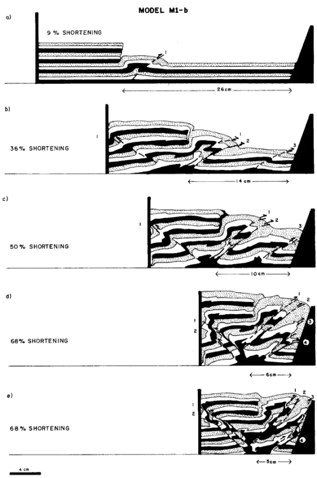
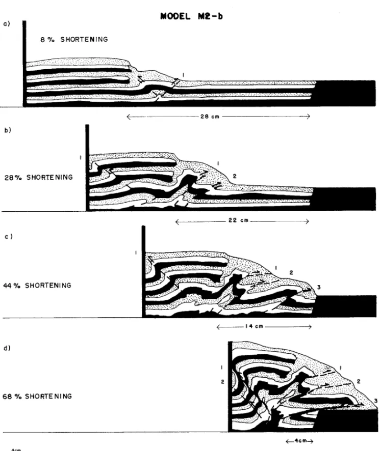
In models M1-b and M2-b, an antiformal stack was formed in a similar way as in experiments M1-a and M2-a, i.e. through deformation in the foreland fol-lowed by contraction of the hinterland and vertical strain (Figs. 8 and 10).
At the beginning of deformation of models M1-b and M2-M1-b, an ordinary duplex system develops, and a backthrust appears in the deformable back-stop (Figs. 8a, b and 10a, b). The progressive de-formation shown in figures 8 (c, d) and 10 (c, d) demonstrates that the deformable backstop impedes the strong back rotation of the oldest forethrusts (1 and 2), as occurred in the M1-a experiment and also in other previously published experiments (e.g. Mu-lugeta & Koyi 1992; Huiqiet al.1992). Forethrusts 1 and 2 undergo only a slight back rotation and when the high obstacle, in model M1-b, interrupts the nor-mal evolution of the duplex, i.e. after 30% shorten-ing (Fig. 8b), the slip on forethrusts and backthrusts increases. The high resistance to sand layer dis-placement generates, after 50% contraction, a new forethrust (4) and backthrust (2), as well as the con-vergence between the trailing and leading branch lines (Figs. 8c and d). Forethrusts and backthrusts accommodated further contraction by strain in the vertical direction, producing a pop-up-like structure (Figs. 8d and e).
GEOMETRY AND KINEMATICS OF EXPERIMENTAL ANTIFORMAL STACKS 207
low resistance in the foreland. This low resistance leads to fewer forethrusts after 68% shortening. The geometry of the M2-b antiformal stacks differs from that of model M1-b only by showing a higher basal horizontal displacement.
In models M1-b and M2-b, the deformable backstop accommodates part of the deformation through backthrusting. In addition, during the evo-lution of the antiformal stack, smaller back rotation of the older forethrusts and lower vertical strain oc-cur in the hinterland than in models M1-a and M2-a. These models demonstrate that, to produce an an-tiformal stack, a deformable backstop requires less shortening than a rigid one (68% in model M2-b vs. 80% in model M2-a). Finally, the series “b” exper-iments reveal that the deformable backstop causes less partitioning of deformation between foreland and hinterland in an antiformal stack.
Sequence M3−aand M3−b: HighObstacle and Thin Sand Layer
The main factor controlling the formation of the an-tiformal stacks in these experiments is the extremely low thickness of the initial sand layer (0.9 cm). The relationship between the sand layer thickness and the spacing between thrusts has been previously docu-mented by Huiqiet al. (1992). Variations in sand column thickness cause different deformation rate due to the change in sand volume. The smaller the volume, the smaller is the minimum principal stress, σ3, which is vertical in a compressional system. As
a consequence, the differential stress(σ1−σ3)
ap-plied to the sand pack increases more quickly with a smaller volume, causing a higher deformation rate, i.e. a larger number of faults form with a smaller fault spacing, for a given shortening.
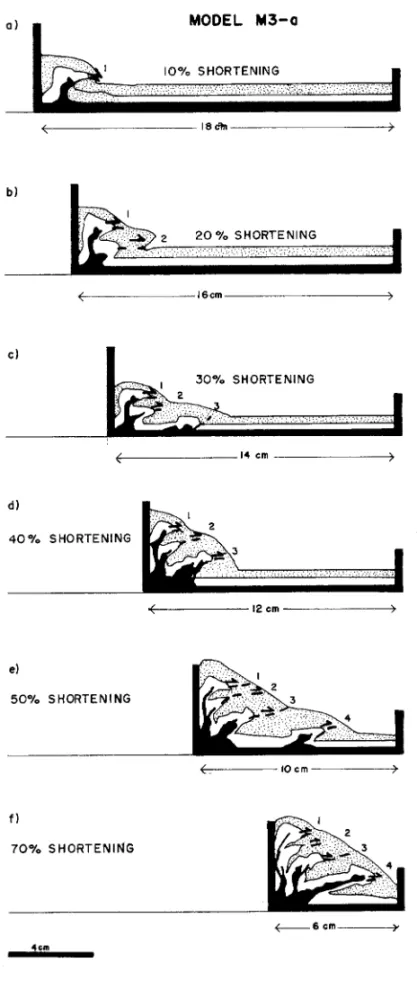
Deformation of model M3-a, set up with a rigid backstop (Fig. 11), confirms that a thin sand col-umn deforms along closely spaced thrusts. In ad-dition, shortening promotes high slip on the thrusts and consequent thickening of the deformation front. The first two thrusts are immediately back rotated in order to accomodate progressive shortening (Figs.
11a, b). After 30% shortening (Fig. 11c), a new forethrust forms, further away, and the process re-peats with thrust back rotation, vertical strain and convergence between branch lines (Figs. 11d-f). Exactly the same kinematic process occurs in model M3-b (Figs. 12b-d).
Model M3-b was carried out with a 3.0 cm thick deformable backstop, much thicker than the sand layer (0.9 cm). In the initial stage of shortening, the backstop strongly resisted deformation (Figs. 12a-d), producing structures in the sand layer which are very similar to those of model M3-a (Fig. 11). With further shortening, the influence of the obstacle in the foreland impedes the displacement of the thrust wedge. The resistance of the obstacle exceeds the resistance of the sand backstop, and a backthrust forms (Fig. 12e). The important point in this model is that the large back rotation of the oldest forethrusts (1 and 2) may be attributed to the rigidity of the thick deformable backstop. The slightly different geometries between models M3-a and M3-b result from the higher vertical strain in the former, caused by its stiffer backstop.
The typical evolution of a duplex system, as in the initial stages of deformation in models M1-a and M2-a, does not occur in models M3. Instead, thrust-ing, back rotation and vertical strain begin at lower displacement and continuously produce an antifor-mal stack (Figs. 11 and 12).
Model M3-b (Figs. 12d and e) has produced the best simulation of an anticlinal stack, when com-pared to McClay’s definition (Fig. 1). Thus, this ex-periment reveals that an obstacle in the foreland, a high deformation rate and low edge effect, due to the backstop, constitute the main boundary conditions for antiformal stack formation in sandboxes.
Models M4, M5, M6and M7(Antiformal Stack Modelling Under Additional Factors)
Models M4 were tilted 5◦forward after model
GEOMETRY AND KINEMATICS OF EXPERIMENTAL ANTIFORMAL STACKS 208
GEOMETRY AND KINEMATICS OF EXPERIMENTAL ANTIFORMAL STACKS 209
GEOMETRY AND KINEMATICS OF EXPERIMENTAL ANTIFORMAL STACKS 210
exactly the same way as the horizontal models M2-a and M2-b. In contrast, the results of models M5, M6 and M7 show some differences in the geometry of the antiformal stack.
Models M5 had a wedge shaped horizon-tal sand layer thinning toward the foreland above a hinterland dipping base. These models were also carried out using two types of backstop (Figs. 14 and 15). A different fault system was formed than those observed in previous models, probably due to the foreward decrease in the thickness of the sand layers above the dipping base. In the initial stages of deformation, the system can be classified as an independent ramp anticlinethrust system (McClay, 1992) (Figs. 14b and 15b). With greater shortening, however, the displacement is blocked at the foreland and each ramp system undergoes back rotation. Af-ter 56 and 53% shortening in models a and M5-b, respectively, only the forethrusts closest to the obstacle (2, 3 and 4 (Fig. 14c) and 3, 4 and 5 (Fig. 15c)) become an antiformal stack with coincident branch lines. In contrast with models M1-b (Fig. 8), M2-b (Fig. 10) and M3-b (Fig. 12), the de-formable backstop in model M5-b does not appear to have affected the fault geometry in front of it.
Experiments M6 (Fig. 16) and M7 (Fig. 17), set up with sandpaper to provide a high basal fric-tion, show a strong increase in the critical wedge ta-per. In the horizontal box (model M6), the high basal friction inhibits the formation of a duplex system during the early stages of deformation. Shortening produces antiformal stacks only by thrusting, back rotation and vertical strain of the analogue material (Fig. 16). A similar evolution has been observed in models M3-a (Fig. 11) and M3-b (Fig. 12). In these models, however, the increase in the wedge taper was a consequence of both the low thickness and the relatively short length of the sand layers.
The effect of basal friction has been discussed by Huiqiet al.(1992), who demonstrated that an in-crease in basal friction produces an inin-crease in both the critical taper and the length of each thrust plane. Models M6 (Fig. 16) and M7 (Fig. 17) differ in the
length of the thrust slices and in the displacement of the foreland. The longer thrust slices and larger fault slips in model M7 (Fig. 17) are interpreted as a con-sequence of the easier foreland displacement due to the decreasing thickness of the sand layer over the tilted base.
DISCUSSION
The experiments described above demonstrate that antiformal stacks result from the interruption or complete impediment of the regular forward devel-opment of a foreland-vergent duplex system. Phys-ical models show intense deformation in the hinter-land due to the obstruction of displacement at the de-formation front. However, some important param-eters acting on deformation of natural rocks, such a pore-fluid pressure and the plastic behavior of rocks in the deeper parts of crystalline thrust sheets, could not be considered in the experiments.
The evolution of thrust systems in the external parts of mountain belts are relatively well studied in their theoretical aspects (e.g. Daviset al. 1983; Dahlen 1990; Suppeet al. 1992; Mosar & Suppe 1992). Analogue modelling of thrust systems in accretionary wedges and fold-and-thrust belts are in broad agreement with the critical-taper Coulomb wedge model (Huiqiet al. 1992).
In the internal parts of orogens, thrusting trans-ports slices of basement rock and produces complex thrust systems. Hatcher & Hooper (1992) reviewed the existing mechanical models of thrust faulting in both external and internal parts of orogens and discussed their features. They proposed a rheo-logical relationship between the three end-members of thrust sheet types: accretionary wedge, foreland fold-thrust belts and crystalline thrust sheets (type C and type F), and argued that one type of thrust sheet may evolve into another during progressive defor-mation.
crys-GEOMETRY AND KINEMATICS OF EXPERIMENTAL ANTIFORMAL STACKS 211
Fig. 13 – Model M4-b in three successive stages (the same boundary conditions as in model M2-b with additional 5◦tilt towards the hinterland). After (a) 18%; (b) 36%; and 50% shortening. Deformation is the
same as in model M2-b.
talline thrust sheets are characterized by a greater inherent strength because of their composition and the lack of initial horizontal layering which charac-terizes thin-skinned settings. In accretionary wedge and foreland fold-thrust belts, however, horizontal layering is assumed to provide zones of weakness along which detachments may occur. Since these
zones of weakness are not taken into account in the analogue models presented here, we may assume that the basic principles of physical modelling re-main valid for the internal parts of orogens.
GEOMETRY AND KINEMATICS OF EXPERIMENTAL ANTIFORMAL STACKS 212
Fig. 14 – Model M5-a with a 5◦inclined basal wedge in the foreland and a rigid backstop. (a) After 20%
shortening; (b) after 31% shortening, a duplex system consisting of independent ramp anticlines is formed; and (c) after 56% shortening, the youngest independent ramp anticline has become an antiformal stack.
continent-continent or arc-continent collision zones. In sand models, antiformal stacks only form when the advancement of the foreland is totally (models M1, Figs. 7 and 8; and models M3, Figs. 11 and 12) or partially blocked (models M2, Figs. 9 and 10). As a consequence, the older thrust sheets of the hinterland pile up above the younger ones. In colli-sion zones, the subducted plate acts as an obstacke, the key boundary condition to form antiformal stack systems (models M1, M2 and M3). In external
oro-genic zones, obstacles may exist but only in special structural settings. They occur where pre-existing faults produce basement highs during tectonic inver-sion, or where the dip of the detachment impedes progressive displacement (see models M4-b, Fig. 13; M5, Figs. 14 and 15; and M7, Fig. 17), as shown by Jadoonet al.(1992) in the Sulaiman fold belt in the western margin of the Indian plate.
GEOMETRY AND KINEMATICS OF EXPERIMENTAL ANTIFORMAL STACKS 213
Fig. 15 – Model M5-b with a 5◦inclined wooden wedge in the foreland and deformable backstop.
GEOMETRY AND KINEMATICS OF EXPERIMENTAL ANTIFORMAL STACKS 214
Fig. 16 – Model M6 with a high basal friction and a horizontal base, after 45% shortening. The high basal friction inhibits the displacement of the foreland, producing a compressional system characterized by strong vertical strain. Note the geometry of the bottom black layer.
Fig. 17 – Model M7 with a high basal friction and a 5◦inclined basal wedge in the foreland, after 56% shortening.
This model shows a similar antiformal stack as in model M1.
sequence (Boyer 1978, Boyer & Elliott 1982) fails to explain some thrust system geometries. The ex-periments in his study also suggest that this model for duplex evolution is not always appropriate. My experimental results demonstrate that the presence of an obstacle causes thrust systems to evolve from an initial forward-breaking sequence in the foreland, to continued deformation in the hinterland. The last stages of shortening in models M1 and M2 (Figs. 7c, d; 8c, d; 9c, d and 10c, d) characterize well this evolution. When the youngest fault reaches the ob-stacle in the foreland, synchronous thrusting occurs on this fault and along the reactivated oldest thrusts, in the hinterland.
Thrust systems also evolve from an
alternat-ing deformation between foreland and hinterland as seen in models M3 and M6 (Figs. 11, 12 and 16), where each thrust was immediately followed by ver-tical strain in the hinterland. A comparison between models M1/M2 and model M3 demonstrates that an initially thick sand layer promotes propagation of deformation into the foreland before deformation resumes in the hinterland.
GEOMETRY AND KINEMATICS OF EXPERIMENTAL ANTIFORMAL STACKS 215
Model M6 (Fig. 16) shows that a high basal friction induces formation of antiformal stacks sim-ilar to those shown in models M3-a (Fig. 11f) and M3-b (Fig. 12d), which were carried out with a low basal friction and an obstacle in the foreland. Therefore, these experimental results suggest that the impediment to foreland displacement does not need to be an obstacle at the deformational front, but simply a high friction basal detachment.
While the geometry and deformation mecha-nisms of model M6 are in good agreement with those of model M3, the geometry and deformation of model M7 (Fig. 17) (also set up with a high basal friction) is somewhat similar to experiments M1 (Fig. 7). The antiformal stack of model M7 developed in a piggy-back sequence with a minor back rotation of the early thrusts. The differences between models M6 (consisting of a sand layer with constant thickness) and M7 (the sand layer thick-ness decreases) are probably due to the decreasing resistance to propagation of the deformation front in model M7.
The decreasing thickness of the sand layers in models M5-a and M5-b (Figs. 14 and 15) favors faster propagation of the deformation front. This feature can be observed by comparing model M5-a (Fig. 14b) with models M1, M2 and M3 (Figs. 7b, 9b and 11c) at 30% shortening. The relatively small amount of vertical strain in front of the backstop (Fig. 14c), which in other models has produced a steep surface slope (Daviset al. 1983), results from the lower resistance to displacement of the defor-mation front. As a consequence, only the youngest ramp anticline that impinges on the foreland obstacle produces an antiformal stack (forethrusts 2, 3 and 4, Fig. 14c; and forethrusts 3, 4 and 5, Fig. 15c). De-formation higher than the 53% shortening of models M5 and M7 would likely transform the entire thrust system into an antiformal stack, pushing the oldest thrusts over the younger ones.
The experiments also show that a deformable sand backstop strongly influences the geometry of thrust systems. The presence of a sand backstop
reduces the strong back rotation of the oldest thrusts in the hinterland, which is common in the experi-ments using rigid backstops (compare Figs. 7d and 8d or Figs. 9d and 10d). During progressive short-ening, the sand backstop becomes involved in the deformation through nucleation of backthrusts.
Model M3-b (Figs. 12d, e), which has pro-duced the best antiformal stack simulation, demon-strates that its formation requires some amount of backstop-edge effects. This fact confirms the anal-ysis made by Byrneet al. (1993) about backstops within a forearc at subduction zones. They con-cluded that backstops are stronger than the rocks lying further trenchwards, deform little but may in-fluence the kinematics of the trench rocks. Thus, the sand backstop should represent a much better equiv-alent for a natural backstop than the rigid moving wall.
CONCLUSIONS
From the above results, several conclusions may be drawn with respect to development of antiformal stacks:
(1) Antiformal stacks form when there is an im-pediment to the progressive evolution of a forward-breaking thrust system. This impediment may be related either to the presence of an obstacle in the foreland or to a high friction along the basal detach-ment. In nature, obstacles could be a ramp in a crys-talline detachment in the internal parts of orogens, or basement highs during tectonic inversion.
(2) Antiformal stacks develop in two different ways:
(a) from an initial thrust system undergoing a piggy-back evolution until an obstacle blocks the de-formation front, causing reactivation of thrusts in the hinterland and further convergence of branch lines (models M1, M2, M4, M5 and M7);
GEOMETRY AND KINEMATICS OF EXPERIMENTAL ANTIFORMAL STACKS 216
(3) The interruption of the piggy-back thrust se-quence causes synchronous thrusting in both fore-land and hinterfore-land.
(4) A variation in the obstacle geometry only changes the geometry of the antiformal stack, but does not modify the deformation processes.
(5) A small slope (5◦) of the basal detachment
pro-duces geometric differences in the thrust system only when the initial sand layer thickness decreases towards the foreland.
(6) The use of a deformable sand backstop reveals that caution should be taken in using a moving wall as a rigid backstop in experiments. The rigidity of the backstop may induce an abnormal vertical strain.
(7) Model M3-b (Figs. 12d, e) which produced the best simulation of an antiformal stack evolution, suggests that antiformal stacks result from a com-bination of the following boundary conditions: a) the presence of an obstacle in the foreland, b) a high deformation rate (i.e. a large number of faults form with a small fault spacing, due to thin sand layers) and c) an edge effect in the hinterland of the thrust system, caused by a deformable backstop.
ACKNOWLEDGEMENTS
I thank the Universidade Federal de Ouro Preto for providing financial assistance through a re-search studentship to Juliano Efigênio Ferreira. I am greatly indebted to Gary Karner and João Hip-pertt for useful suggestions and careful correction of the English.
REFERENCES
Bally AJ, Gordy PL & Stewart GA.1966. Structure, seismic data and orogenic evolution of the Southern Canadian Rockies. Bull Canad Petrol Geol 14: 337-381.
Boyer SE.1978. Structure and origin of the Grandfa-ther Mountain window, North Carolina.Ph.D. thesis. John Hopkins University.
Boyer SE.1992. Geometric evidence for synchronous thrusting in the southern Alberta and northwest Mon-tana thrust belt. InThrust Tectonics, eds. KR Mc-Clay. London, Chapman and Hall, p. 377-390.
Boyer SE & Elliott D.1982. Thrust systems.Am Ass Petrol Geol Bull66:1196-1230.
Byrne DS, Wang W & Davis D.1993. Mechanical role of backstops in the growth of forearcs.Tectonics,12: 123-144.
Dahlen FA.1990. Critical taper model of fold-and-thrust belts and accretionary wedges. An Rev Earth Plan Sci18:55-99.
Dahlen FA, Suppe J & Davis D.1984. Mechanics of fold-and-thrust belts and accretionary wedges: Co-hesive Coulomb theory.J Geophys Res89: 10,087-10,101.
Dahlstrom CDA.1969. Balanced cross-section.Canad J Earth Sci6:743-757.
Davis D, Suppe J & Dahlen FA. 1983. Mechanics of fold-and-thrust belts and accretionary wedges. J Geophys Res94:10347-54.
Elliott D & Johnson MRW.1980. Structural evolution in the northern part of the Moine thrust belt, NW Scotland. R S Edinburgh Trans71:69-96.
Hatcher RD & Hooper RJ.1992. Evolution of crys-talline thrust sheets in the internal parts of mountain chains. InThrust Tectonics, eds.KR McClay. Lon-don, Chapman and Hall, p. 217-233.
Hubbert MK.1937. Theory of scale models as applied to the study of geologic structures.Geol Soc Am Bull 48:1459-1520.
Huiqi L, McClay KR & Powell D.1992. Physical models of thrust wedges. InThrust Tectonics, eds.
KR McClay. London, Chapman and Hall, p.
71-81.
GEOMETRY AND KINEMATICS OF EXPERIMENTAL ANTIFORMAL STACKS 217
Marshak S, Wilkerson MS & Hsui AT.1992. Genera-tion of curved fold-thrust belts: Insight from simple physical and analytical models. InThrust Tectonics
eds. KR McClay. London, Chapman and Hall, p.
83-92.
McClay KR.1990. Extensional fault systems in sedi-mentary basins: a review of analogue model studies. Marine Petrol Geol7:206-233.
McClay KR.1992. Glossary of thrust tectonics terms. In Thrust Tectonicseds. KR McClay. London, Chap-man and Hall, p. 419-433.
McClay KR & Ellis PG.1987. Analogue models of extensional fault geometries. InContinental Exten-sional Tectonics, edsMP Coward, JF Dewey & PL Hancock. Geol Soc Special Publication28: 109-125.
McClay KR & Scott AD.1991. Experimental models of hangingwall deformation in ramp-flat listric exten-sional fault systems.Tectonophys188:85-96.
Mitra S.1986. Duplex structures and imbricate thrust systems: Geometry, structural position, and hydro-carbon potential. Am Ass Petrol Geol Bull Bulletin 70:1087-1112.
Mosar J & Suppe J.1992. Role of shear in fault-propagation folding. InThrust Tectonics, eds. KR McClay. London, Chapman and Hall, p. 123-132.
Mulugeta G & Koyi H.1992. Episodic accretion and strain partitioning in a model sand wedge. Tectono-phys202:319-333.
Muñoz JA.1992. Evolution of a continental collision belt: ECORS-Pyrenees crustal balanced cross-section. InThrust Tectonics, eds. KR McClay. London, Chapman and Hall p. 235-246.
Suppe J, Chou GT & Hook SC.1992. Rates of folding and faulting determined from growth strata. InThrust Tectonics, eds.KR McClay. London, Chapman and Hall, p. 105-122.
Vendeville B, Cobbold PR, Davy P, Brun JP &
Choukroune P.1987. Physical models of