`
Development of an
Algorithm for a
GNSS/MEMS-IMU/Imaging
Coupled System for
Direct
Georeferencing
Wenlin Yan
Engenharia Geográfica
Departamento de Geociências Ambiente e Ordenamento do
Território
2017
Orientador
M. Luísa M. C. Bastos, Investigador Principal,
Faculdade de Ciências da Universidade do Porto
Coorientador
José A. Gonçalves, Professor Auxiliar,
Faculdade de Ciências da Universidade do Porto
Time always goes by quickly. I still remember the situation when I came to Porto in February 2011. At that time I had the ambition to reach a great academic level in several years, and this wish was like the leaves of a cup of tea: at the beginning they are holding on the top of the water, after a period of time they extend and subside gradually, meanwhile the tea becomes more and more flavored.
At first, I would like to give my gratitude to my supervisor Dr. Luísa Bastos and Porto University, because she and the university provided me the means for further opportunities and to get the experience in GNSS/IMU related applications. Because of this chance, not only my methodologies to deal with academic problems, but also the thinking of life were improved or redesigned. Secondly, great respect should be delivered to my co-supervisor Prof. José A. Gonçalves, his excellent acknowledge and skill in photogrammetry inspired me greatly, and his suggestions becomes the critical part of this thesis. I would like to give my thanks to the colleagues, Mr. Américo Magalhães, an excellent engineer to validate the designed tests, and he always gives timely help to my living problems in Porto; Dr. Dalmiro Maia, Dr. Sérgio Madeira, Dr. Richard Deurloo, Dr. Machiel Bos, Mr. Diogo Ayres-Sampaio, Dr. Paulo Marreiros and the other excellent researchers I met in Portugal, the conversations with those peoples benefit me from different aspects of the academic; Ms. Mónica Sofia Guerreiro Rodrigues, her “Bom Dia” gives me a delighted start every day; I would like to further acknowledge Prof. Rui Moura, from the Faculty of Science of the University of Porto, for conducting the flight tests in the Espinho area.
Meanwhile, I would also give my thanks to the project of “PITVANT” (Projecto de Investigação e Tecnologia em Veículos Aéreos Não-Tripulados) funded by the Portuguese Ministry of Defense, and the project of “DEOSOM” (Detection and Evaluation of Oil Spills by Optical Methods), those project give me the opportunities to work in Porto University from 2011 to 2013, and this work experience gives me a good start for the further PhD study.
Then, I also want deliver my thanks to some researchers in China side: Prof. Jian Wang and Prof. Jingxiang Gao, thanks for their guiding in many aspects not only in academic since the
commercial photogrammetry software from your company; Prof. Guochang Xu and Prof. Tianhe Xu, thanks for your work opportunities in Shandong University, and the guides of the robust adaptive Kalman Filter; Prof. Qiuzhao Zhang, Prof. Chao Liu, Dr. Feng Zhou, thanks for the conversations in GNSS area, and also want to give many apologies to the persons who gave me support but not possible to mention in this thesis.
Finally, I would like to give thanks to my familly members: my little daughter Anna Yan, her birth brought me joy beyond description; my wife Ying Kang, her love to me becomes the pills to kill off the pains from any crisis in my life; my mother and father, my mother and father in law, and my brother and his wife, thanks for all their understanding and support.
Nos levantamentos fotogramétricos aéreos a determinação de parâmetros de orientação externa precisos é um aspecto crítico da georeferenciação direta. O desempenho do sistema de Posicionamento e Orientação (POS Position and Orientation System), em particular a precisão da orientação, é um dos fatores mais importantes para fotogrametria aérea, especialmente quando são usados veículos aéreos ligeiros, incluindo veículos não tripulados (UAV, Unmanned Aeral Vehicles). O baixo custo do POS que atualmente são usados na maioria dos veículos aéreos ligeiros, nomeadamente em UAVs, possuem algumas limitações, como a baixa precisão na orientação, que é obtida a partir de sensores MEMS IMUs (Micro-Electro-Mechanical System, Inertial Measurement Units) de baixa precisão. Neste contexto, a precisão da orientação de um POS de baixo custo, que possa ter um desempenho equivalente a um POS de grau superior, é do maior interesse.
A precisão de um POS pode ser melhorada otimisando as estratégias de integração de sistemas GNSS e IMU, com base em diferentes arquiteturas de acoplamento, tais como integração loosely, tightly, ou deeply coupled e uma configuração apropriada do filtro de Kalman utilizado, e/ou através da incorporação de informações adicionais, provenientes por exemplo de um radar, odómetro, modelo de terreno, etc. Na última década, com a disponibilidade de câmaras de alta resolução de menor custo, outras estratégias tornaram possível explorar a fusão de medidas GNSS e IMU com imagem para melhorar a precisão do POS. A disponibilidade de sensores miniaturizados, com capacidades melhoradas, e novos métodos para o processamento de imagem, juntamente com o aparecimento das plataformas aéreas ligeiras, para aquisição de dados, nomeadamente os veículos não tripulados abriu uma série de novas possibilidades para aplicações de navegação geodésica, alavancando novos desenvolvimentos na fusão de sensores. Dada a limitação da capacidade de carga e fornecimento de energia nos veículos aéreos pequenos, foi desenvolvido um o algoritmo GNSS/MEMS-IMU que integra também informação das imagens obtidas pela câmara acoplada ao sistema. Esta abordagem tem a vantagem de permitir mellhorar o desempenho do sistema com base na concepção e configuração adequada do filtro usado no algoritmo de processamento, e sem a introdução de quaisquer dispositivos adicionais.
Neste trabalho, foi implementado um sistema de georeferenciação direta simples e barato, composto por um receptor GNSS de frequência dupla, um IMU de baixo custo e uma pequena câmara digital, para uso em plataformas aéreas ligeiras. Com o objetivo de melhorar o desempenho de orientação deste tipo de sistema de baixo custo, projetado para ser usado em
seguintes principais aspectos:
1) Validação dos algoritmos de triangulação aérea, georeferenciação direta (forward
intersection) e ajuste do levantamento fotogramétrico com este sistema.
2) Validação das funções de navegação de integração GNSS/MEMS-IMU aplicando um
Filtro de Kalman de 15 estados, demonstração de equivalência do Filtro de Kalman de loosely e tightly coupled sob a condição de haver boa visibilidade nas observações GNSS.
3) Implementação de um Filtro de Kalman GNSS/MEMS-IMU aumentado com a
informação geométrica obtida a partir de imagens consecutivas, uma vez que a orientação relativa pode ser obtida com precisão a partir de imagens consecutivas usando um algoritmo SIFT/SFM (Scale-Invariant Feature Transform/Structure From Motion) apropriado. A incorporação no Filtro de Kalman desta informação sobre a orientação relativa permite melhorar significativamente a precisão dos parâmetros de orientação externa.
4) Utilização de um Filtro de Kalman robusto adaptativo, com a determinação do fator
adaptativo e do fator robusto realizado pela informação de inovação e pelo estabelecimento de limites para os valores relativos a mudanças de orientação entre imagens consecutivas, o que permite melhorar ainda mais o desempenho do novo método.
Os resultados dos testes aéreos reais usados para avaliar o desempenho do método confirmam a sua eficiência. Os resultados mostram que usando uma câmara simples e barata, a solução de orientação resultante da integração GNSS/MEMS-IMU pode ser melhorada significativamente até cerca de 60% se a informação geométrica obtida das imagens for introduzida. Melhoria adicional pode ser obtida aplicando um Filtro de Kalman robusto adaptativo. Os testes também mostraram que a precisão do método proposto depende, fundamentalmente, da taxa de sobreposição das imagens e da qualidade da câmara.
O sistema implementado garante uma solução de orientação de boa qualidade para aplicações fotogramétricas usando veículos aéreos ligeiros (incluindo UAVs) com a vantagem de ser eficiente e acessível. Esse tipo de abordagem pode ser explorada para uso em outros tipos de aplicações, como a navegação em ambientes desafiantes.
Palavras-chave: GNSS/MEMS-IMU/Imaging navegação acoplada; POS; Georeferenciação direta; Filtro
The determination of precise exterior parameters is critical for aerial photogrammetric surveys, particularly for direct georeferencing. The performance of the Position and Orientation System (POS), in particular the orientation accuracy, is one of the most important factors in aerial photogrammetry specially when it is based on light airborne vehicles, including unmanned vehicles (UAV, Unmanned Aeral Vehicles). The low cost POS systems that are currently used in most of the light aerial vehicles, particularly in UAVs, have some weaknesses, such as the low accurate orientation, which is derived from the low accuracy MEMS IMUs (Micro-Electro-Mechanical System, Inertial Measurement Units). In this context, the exploration of the improvement of orientation accuracy of low cost POS, to provide equivalent performance as the high grade POS, is of utmost interest.
The accuracy of a POS can be improved by optimizing strategies of the integration system of GNSS and IMU, based on different coupling architectures, such as loosely, tightly or deeply coupled integration and proper filter configuration in Kalman Filter, and/or through incorporation of additional information, such as radar, odometer, terrain aiding, etc. In the last decade with the availability of cheaper high resolution cameras, other strategies are possible exploring the fusion of the measurements of GNSS, IMU and imagery to improve the accuracy of the POS. The availability of miniaturized sensors with enhanced capabilities and new methods for image processing together with the booming of light airborne platforms, for data acquisition, particularly in unmanned vehicles, opens a range of new possibilities for geodetic navigation applications, leveraging new developments in sensor fusion. Due to the limitation of payload capacity and power supply of the light aerial vehicles, an algorithm for a GNSS/MEMS-IMU was developed, in which it also integrates the information from images obtained by the camera attached to the system. This method has an advantage that, the improvement to the system is only depend on the design and appropriate configuration of the filter used in the algorithm, without introducing any additional devices.
In this work, a simple and cheap direct georeferencing system, consisting of a GNSS receiver, a low cost IMU and a small digital camera, for the use in light airborne platforms, was Implemented. Aiming at improving the orientation performance of this type of low cost system, which is designed to be used on light airborne vehicles, the research work presented in this
1) Validate the algorithms of aerial triangulation, direct georeferencing (forward intersection), and bundle adjustment for the photogrammetric survey with this system.
2) Validate the GNSS/MEMS-IMU integration navigation functions by applying a 15-state
Kalman Filter, and prove the equivalence of the loosely and the tightly coupled Kalman Filter under the condition of good GNSS visibility.
3) Implement a GNSS/MEMS-IMU Kalman Filter augmented with the geometric information
retrieved from consecutive images, as the precise relative orientation of consecutive images can be obtained using a SIFT/SFM (Scale-Invariant Feature Transform/Structure From Motion) matching algorithm. Incorporating this relative orientation information in the Kalman Filter improves the accuracy of the exterior orientation parameters.
4) Use a robust adaptive Kalman Filter, with the determination of the adaptive factor and
the robust factor accomplished by the innovation information and the threshold value of the orientation changes between consecutive images respectively, to further improve the performance of the new method.
Results from real airborne tests were used to assess the performance of the method and confirm its efficiency. The results show that using a simple cheap camera, the solution of the orientation resulting from the integration of GNSS/IMU-MEMS can be improved significantly by about 60%, if the geometric information obtained from the images is introduced. An additional improvement can be obtained by applying a robust-adaptive-image Kalman Filter. The tests also show that the accuracy of the proposed method is dependent on the overlapping rate as well as the quality of the camera.
The system implemented guarantees a good quality orientation solution for photogrammetric applications using light aerial vehicles (including UAVs) with the advantage of being efficient and affordable. This type of approach can be further exploited for use in other types of applications, such as navigation in challenging environments.
Keywords: GNSS/MEMS-IMU/Imaging coupled navigation; POS; Direct georeferencing;
1 Introduction ... 1
1.1 State of the art ... 2
1.2 Motivation ... 6
1.3 Objective and main contributions of this thesis ... 7
1.4 Thesis outline ... 8
2 Global navigation satellite systems ... 11
2.1 GNSS overview ... 11 2.1.1 GPS ... 12 2.1.2 GLONASS ... 13 2.1.3 Galileo ... 14 2.1.4 BDS ... 15 2.2 Measurement models ... 16
2.3 Position and velocity estimation using GPS ... 22
2.3.1 Standard position and velocity estimation ... 22
2.3.2 Precise positioning strategies ... 24
2.4 GNSS processing software ... 27
3 Direct Geo-referencing ... 29
3.1 DGS overview ... 29
3.2 Photogrammetry image processing ... 30
3.2.1 Backward intersection based on Ground Control Points ... 35
3.2.2 Forward intersection based on stereo images ... 37
3.2.3 Bundle adjustment ... 39
3.3 The process of GNSS/IMU aided photogrammetry ... 41
3.4 Automatic extraction of feature points of the image ... 45
3.4.1 Area based matching method ... 46
3.4.2 Feature Based Matching method ... 47
3.5.2 Test 2 – Espinho 2016 ... 56
3.6 Summary ... 60
4 Kalman Filter ... 63
4.1 Reference frames ... 63
4.2 Introduction to Kalman Filter ... 64
4.2.1 In linear systems ... 65
4.2.2 In none-linear systems: ... 66
4.3 Inertial mechanical navigation equations ... 67
4.4 Applying the Kalman Filter ... 70
4.4.1 The prediction process ... 70
4.4.2 Measurement update ... 72
5 Development of a GNSS/MEMS-IMU/Imaging Kalman Filter algorithm ... 79
5.1 Equivalence of GNSS/INS loosely and tightly coupled Kalman Filter under the condition of good GNSS observation scenario ... 80
5.1.1 The equivalence of the loosely and tightly coupled strategies ... 80
5.1.2 Validation test ... 84
5.2 GNSS/MEMS-IMU/Imaging Coupled System ... 86
5.2.1 Relative geometric information retrieved from images ... 87
5.2.2 Applying the GNSS/IMU/Imaging Kalman Filter ... 89
5.3 Robust adaptive Kalman Filter ... 91
6 Results and analysis ... 95
6.1 Sensors and campaigns ... 95
6.1.1 Sensors ... 95
6.1.2 Campaigns ... 98
6.2 Summary ... 106
7 Conclusion and recommendations ... 109
Recommendations for Future works ... 111
References ... 113
Appendix A. The estimation of satellite position and velocity from ephemeris ... 121
Table 1-1 Performance characteristics of inertial navigation systems ... 3 Table 1-2 Thee commercial UAV photogrammetric survey system ... 5 Table 2-1 The ephemeris products list. ... 22 Table 3-1 Statistics of the accuracy of the exterior orientation parameters obtained by the
IGI AeroControl POS ... 50 Table 3-2 The specification of Camera TOPDC-4. ... 51 Table 3-3 The difference between the backward intersection output of the of the developed software and “ZI-Imaging ImageStation”. ... 53 Table 3-4 The comparison of the result of forward intersection of image pair 2013-2014. 53 Table 3-5 The comparison of the result of forward intersection of image pair 3013-3014. 53 Table 3-6 The exterior orientation parameters difference between the bundle adjustment
and “ZI-Imaging ImageStation” software. ... 54 Table 3-7 The coordinates difference between the bundle adjustment and GCPs. ... 55 Table 3-8 The specification of Camera Sony ICX-204AK CCD ... 57 Table 3-9 Statistics of differences between GNSS/Litton and the “AGIsoft PhotoScan” AT
(only with GCPs) ... 59 Table 3-10 Statistics of the differences between direct georeferencing and the GCPs ... 60 Table 5-1 Statistics of the difference between the orientation solution obtained with the
loosely and tightly coupled strategies. ... 86 Table 5-2 Statistic of the comparison of the delta orientation solutions from SIFT/SFM and
GNSS/iMar (unit: °) ... 88 Table 5-3 Statistic of the comparison of the delta orientation solutions from SIFT/SFM and
GNSS/Litton (unit: °) ... 88 Table 6-1 The specifications of two MEMS IMUs used in this thesis. ... 96
Table 6-3 Specifications of two cameras used in this thesis. ... 97 Table 6-4 Statistics of the difference between the orientation solutions and reference,
obtained with the classical Kalman Filter for GNSS/Crossbow and
GNSS/Crossbow/Imaging integration and with the robust-adaptive-image Kalman Filter, unit: °. ... 100 Table 6-5 Statistics of difference between the orientation solutions and reference, obtained with the classical KF for GNSS/Xsens and GNSS/Xsens/Imaging integration and with the robust-adaptive-image Kalman Filter for the GNSS/Xsens/Imaging, unit: ° ... 104 Table 6-6 Statistics of difference between the orientation solutions and reference, obtained with the classical KF for GNSS/Xsens and GNSS/Xsens/Imaging integration and with the robust adaptive Kalman Filter for the GNSS/Xsens/Imaging, unit: °. ... 106
Fig. 2-1 GNSS system segments. ... 11
Fig. 2-2 Global Positioning System. ... 12
Fig. 2-3 GLONASS constellation. ... 13
Fig. 2-4 Galileo constellation ... 14
Fig. 2-5 BDS constellation. ... 15
Fig. 2-6 GNSS signal structure. ... 17
Fig. 2-7 The travel of the GNSS signal. ... 17
Fig. 3-1 IGI AEROcontrol. ... 30
Fig. 3-2 Applanix POS AV ... 30
Fig. 3-3 the image coordinate system definition of computer and photogrammetry. ... 31
Fig. 3-4 The interior parameters. ... 31
Fig. 3-5 the objective of the photogrammetry work. ... 32
Fig. 3-6 Collinearity condition. ... 33
Fig. 3-7 The backward intersection method. ... 35
Fig. 3-8 The forward intersection method. ... 37
Fig. 3-9 Photogrammetric project with a small calibration field. ... 41
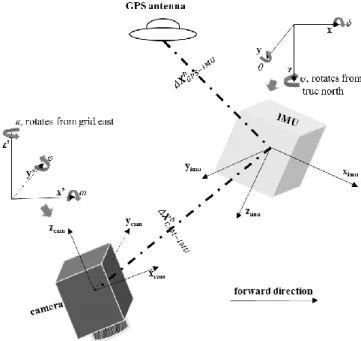
Fig. 3-10 Position offsets and orientation bore-sight between the camera and IMU. ... 42
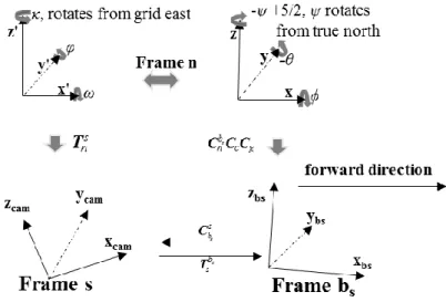
Fig. 3-11 The relationship between the camera frame s and the new body frame bs. ... 43
Fig. 3-12 The search process of the corresponding point at two images. ... 46
Fig. 3-13 Flowchart of the SIFT. ... 47
Fig. 3-14 From photograph to point-cloud: the Structure-from-Motion workflow. ... 49
Fig. 3-17 The configuration of the test of Anyang 2013. ... 51
Fig. 3-18 Trajectory of the Anyang test 2013 projected in Google Earth ... 52
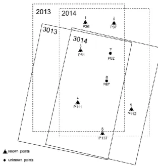
Fig. 3-19 The distribution and appearance of the GCPs of the four images. ... 52
Fig. 3-20 The ground points used for the bundle adjustment test. ... 54
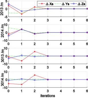
Fig. 3-21 The position exterior parameters convergence process. ... 55
Fig. 3-22 The orientation exterior parameters convergence process. ... 55
Fig. 3-23 The coordinates calculation convergence process of point 62. ... 56
Fig. 3-24 The coordinates calculation convergence process of point 87. ... 56
Fig. 3-25 The configuration of the test of Esphinho 2016 ... 57
Fig. 3-26 Trajectory of the Espinho test 2016 projected in Google Earth, and the distribution of the ground points.. ... 58
Fig. 3-27 Differences of GNSS/Litton and the “AGIsoft PhotoScan” AT (only with GCPs) 58 Fig. 3-28 Differences between direct georeferencing and the GCPs. ... 60
Fig. 4-1 Frames of reference ... 64
Fig. 4-2 A body frame ... 64
Fig. 4-3 Scheme of the loosely coupled Kalman Fitler. ... 73
Fig. 4-4 Scheme of the tightly coupled Kalman Fitler. ... 74
Fig. 5-1 The flow chart of Loosely/Tightly Coupled Strategies. ... 84
Fig. 5-2 Differences of the orientation results obtained with the loosely and tightly coupled strategies. ... 85
Fig. 5-3 IMU samplings (with index “i” and symbol “•”), GNSS update (with index “j” and symbol “|”) and camera exposure events (with index “k” and symbol “▲”). ... 86
Fig. 5-4 Tie points overview of the images with different image overlap rate. ... 87
Fig. 5-5 Comparison of the orientation solutions obtained from the SIFT/SFM approach and the GNSS/iMar ... 88
Fig. 5-6 Comparison of the orientation solutions obtained from the SIFT/SFM approach and the GNSS/Litton. ... 88
Fig. 5-7 Difference between the orientation solutions with and without GCPs, calculated using the AGIsoft SIFM/SFM software ... 89
using robust adaptive Kalman Filter ... 93
Fig. 5-9 Biases estimation of Crossbow IMU. ... 94
Fig. 6-1 NovAtel DL-V3 GNSS receiver and the aerial antenna ... 96
Fig. 6-2 Overview of two MEMS IMUs used in this thesis ... 96
Fig. 6-3 Overview of the two higher grade IMUs for the comparison reference. ... 97
Fig. 6-4 Overview of two cameras used in this thesis. ... 97
Fig. 6-5 Trajectory of the Alentejo test 2011 projected in Google Earth. ... 99
Fig. 6-6 Difference of the orientation solutions obtained with GNSS/Crossbow and with GNSS/iMar, unit: °. ... 100
Fig. 6-7 Difference between the orientation solutions and the reference, obtained with the integration GNSS/Crossbow/Imaging, with and without using the robust-adaptive-image Kalman Filter, unit: °. ... 100
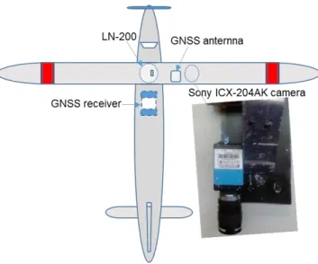
Fig. 6-8 The overview of the light-small aerial vehicle ... 101
Fig. 6-9 The configuration of the test of Esphinho 2013 ... 102
Fig. 6-10 Trajectory of the Espinho test 2013 projected in Google Earth. ... 102
Fig. 6-11 Difference between the orientation solutions and the reference, obtained with the classical KF for GNSS/Xsens and GNSS/Xsens/Imaging integration and with the robust-adaptive-image Kalman Filter for the GNSS/Xsens/Imaging, unit: °. ... 103
Fig. 6-12 The configuration of the test of Esphinho 2017 ... 105
Fig. 6-13 Trajectory of the flight of the test of Esphinho 2017, projected in Google Earth. Ground control points are located along the red line. ... 105
Fig. 6-14 Difference between the orientation solutions and the reference, obtained with the classical KF for GNSS/Xsens and GNSS/Xsens/Imaging integration and with the robust adaptive Kalman Filter for the GNSS/Xsens/Imaging, unit: ° ... 106
List of abbreviations
AT Aerial Triangulation
AO/FCUP Observatório Astronómico do Prof. Manuel de Barros / Faculdade de Ciências da Universidade do Porto
APs Application Programs
BBA Bundle Block Adjustment
BDS BeiDou Navigation Satellite System C/A Coarse/Acquisition
CCD Charged Coupled devices CDMA Code Division Multiple Access
CODE Center for Orbit Determination in Europe DGS Direct Georeferencing System
DOM Digital Orthoimage Mosaic DSM Digital Surface Model ECEF Earth Center Earth Fixed ECI Earth Center Inertial
EGNOS European Geostationary Navigation Overlay Service ESA European Space Agency
FDMA Frequency Division Multiple Access FOG Fiber Optic Gyros
GCPs Ground Control Points
GLONASS GLObal'naya NAvigatsionnaya Sputnikovaya Sistema GNSS Global Navigation Satellites System
GPS Global Positioning System Hz Hertz
IGS International GNSS Service
IGSO Inclined Geosynchronous Satellite Orbit IMU Inertial Measurement Unit
INS Inertial Navigation System
InSAR Synthetic Aperture Radar Interferometry IRNSS Indian Regional Navigation Satellite System
ISPRS International Society for Photogrammetry and Remote Sensing LC Linear Combination
Lidar Light Detection and Ranging LRF Laser Ranger Finder
MEMS Micro-Electro-Mechanical System MSF Russian Military Space Forces MTSAT Multi-Functional Transport Satellite PAF Portuguese Air Force
PITVANT Projecto de Investigação e Tecnologia em Veículos Aéreos Não-Tripulados POS Position and Orientation System
PPP Precise Point Positioning PRN Pseudo-Random Noise
QZSS Quasi-Zenith Satellite System
RNSS Regional Navigation Satellite System SAR Search and Rescue Services
SBAS Satellite Based Augmentation System
SIFT/SFM Scale-invariant Feature Transform, Structure From Motion SMU Sensor Management Unit
SoL Safety-of-Life STD Standard Deviation
WAAS Wide Area Augmentation System
1
Introduction
Equation Chapter (Next) Section 1(code text, Delete final)
In order to describe the world perfectly, neoclassical artists represented by Leonardo Di Serpiero da Vinci pursued to painting the objects with special ideals and skills. The goal of this work is to use the geometric information to model the surface of the earth precisely. The tools that artists used included pencil, brush, and ink, while the tools in this work are GNSS (Global Navigation Satellites System), inertial systems, cameras, coordinates, and pixels. The methodologies used to develop this work involve different geomatics disciplines such as GNSS positioning, GNSS/INS (Inertial Navigation System) coupled navigation, Photogrammetry, as well as Mathematics, Computer vision, and Electronics.
GNSS has been the most outstanding positioning and timing tool since the eighties in the 20 century, with the features such as high accuracy, world-wide coverage, independent of atmospheric conditions, and low cost, which has been widely used in the areas of navigation, timing and geomatics, in the airborne, marine and terrestrial scenarios, both for military and civil purposes. Continuous and accurate GNSS positioning requires a good line of sight visibility of satellites, which makes it difficult to use the GNSS in urban areas, valleys and forests, in which the signals are easily blocked or degraded.
Unlike GNSS, INS is a dead reckoning and self-contained navigation system, used in navigation since the beginning of last century. Inertial systems are not dependent on exterior signals, and can therefore provide a position solutions in every environment, including underwater. An INS can provide continuous position and attitude outputs, and therefore becomes the complement or other navigation aiding source, namely during short term lack of GNSS. Besides, INS has the capacity of giving high rate positioning and attitude results, which can reach several hundred Hertz (Hz), much higher than GNSS (normally from 1 to 20 Hz). However, the drawback of INS is the time-dependent errors of the sensors, which grow fast with time, which means that without a timely correction the performance of an INS will be highly disturbed or even corrupted. Therefore, the integration of GNSS and INS can take the most of the advantages from both systems, and can provide a continuous, accurate, and high rate output of position and attitude solutions, which can be used in many practical applications besides navigation, the classic
application, such as photogrammetry (Cramer et al. 2000, Cramer 2001, Gonçalves and Henriques 2015), strapdown gravimetry (Schwarz et al. 1993, Deurloo 2011, Ayres-Sampaio et al. 2015, Yan et al. 2016) or video photogrammetry (Madeira et al. 2014, Yan et al. 2017). The word “photogrammetry” derives from three words: light, writing and measurement. In 1998, the congress of ISPRS (International Society for Photogrammetry and Remote Sensing), defined it as: Photogrammetry is the art, science, and technology of obtaining reliable information and other physical objects from none-contact imaging and other sensor systems about the earth and its environment, and processes through recording, measuring, analyzing and representation. Photogrammetry relies on the extraction of the geometric information and its main task is to build the relationship between the pixels of the images and the corresponding objects of the world. This technology started in the fiftieth of the 20 century, and went through three stages, analog, analytic and digital, according to the medium types to restore the images, chemical films or digital code, as well as the projection models. Depending on the platforms used, Photogrammetry also can be classified as satellite photogrammetry, aerial photogrammetry, terrestrial photogrammetry, micro-range photogrammetry, and two-media photogrammetry.
Within this context, we are aiming to build a 3D geodetic model of the earth surface through the integration of like technologies of GNSS, INS, Photogrammetry and measurements from other devices. In this thesis, we focused on the exploration of low cost sensors, such as MEMS-IMU (Micro-Electro-Mechanical System, Inertial Measurement Unit) and consumer digital cameras, which were integrated to be strapped on a small light aerial vehicle, and designed in particular for UAV applications, in order to make the photogrammetric survey efficient and, at the sometime more affordable.
1.1
State of the art
Conventional photogrammetric surveys are based on the geometry relationship between the pixel coordinates and the real coordinates of the object, which need a certain amount of GCPs (Ground Control Points). For instance, in traditional aerial photogrammetry, it is a standard procedure to determine the exterior orientation parameters through the so-called Aerial Triangulation (AT) process. The exterior orientation parameters’ quality is dependent on the quantity, distribution and precision of GCPs. High accuracy surveys for the establishment of GCPs involve a certain amount of field work, using for example, RTK GNSS surveying, and are therefore costly. Aerial Triangulation in a large scale mapping work needs even many GCPs. Moreover, in areas without man-made objects ground control point identification can be quite difficult and time consuming.
With the development of GNSS and INS, which can provide the exterior orientation parameters for the photogrammetric survey, reduction of the required GCPs can be considered (Tachibana et al. 2004, Madeira et al. 2014). The integration of GNSS and INS is named as POS (Position and Orientation System). Used together with a digital camera, which should be synchronized with the POS, makes a DGS (Direct Georeferencing System), which allows to transfer object data in the images immediately into a local or global coordinate system making further processing more efficient. For instance, in urban street mapping (Ellum and El-Sheimy 2002, Madeira et al. 2010), coastal monitoring (Madeira et al. 2013), forests monitoring (Hopkinson et al. 2013) and particularly in quick mapping of disaster areas (Hutton and Mostafa 2005, Mitishita et al. 2008). DGS allows a fast characterization of the actual situation, which is of utmost relevance. This has great advantages, especially in terms of cost and efficiency, in comparison with conventional photogrammetry methodologies.
DGS has two core parts: one is the POS and the other is the camera. The POS consists of a GNSS and a IMU. The POS is used for the estimation of the exterior orientation parameters and the camera is used for the acquisition of image information. Many time we see references that in the POS, the GNSS is providing the positions and the IMU is providing the orientations, which is not very precise, because both the results of position and orientation are provided by the integration of the GNSS and IMU.
IMUs are classified into different grades, mainly according to the stability of the inherent bias of the sensors output, normally based on the gyro bias (Jekeli 2001b), or also on the type of applications they are mostly used. Table 1-1 indicates the typical performance of the actual different IMUs grades.
Table 1-1 Performance characteristics of inertial navigation systems (Jekeli 2001b, Hewitson 2006)
sensors performance
parameters
Grade Consumer
(MEMS) Tactical Navigation Military
gyroscope bias °/hr > 10 1.0-10 0.0001-1.0 < 0.0001 scale factor ppm > 500 200-500 1-200 < 50 random walk °/sqrt(hr) - 0.2-0.5 0.002-0.2 - accelerometer bias µg > 500 200-500 1-200 < 10 scale factor ppm > 1000 400-1000 1-400 < 2 random walk µg/hr/sqrt(Hz) - 200-400 5-200 -
From this table we can see that, from the Consumer to the Military applications, the accuracy of the sensors are better and better, and the prices are also becoming higher, from several Euros to millions Euros. The correct specification of the IMU errors is essential to the final GNSS/INS solution quality, and the full error specification includes systematic and random errors, such as initial alignment error, gravity modelling error and linearization error.
There are several commercial POS products that have been brought to market. Since 2002, the PASCO Corporation (now belonging to Trimble) has introduced APPLANIX POS/AV for airborne and terrestrial applications which is combined with high resolution aerial cameras. The company IGI has brought out the AEROcontrol, which consists of an Inertial Measurement Unit based on Fiber Optic Gyros (FOG) and a Sensor Management Unit (SMU) with an integrated high end GNSS receiver. The attitude accuracy of these commercial POS can achieve a few hundredth to thousandth degrees, with a position accuracy from several centimeters to a few decimeters (Kremer and Kruck 2003, Scholten et al. 2003). Those advanced POS, which are using high grade IMUs, integrated with high quality cameras/scanners, have the ability to provide products with high level of accuracy, but with the disadvantage of being very expensive (normally more than 100 thousand Euros). These commercial POS achieving accurate exterior orientation parameters for aerial photogrammetric surveys, relying on the use of tactical or navigation grade IMUs (either with laser or fiber optics gyros). These precision manufacturing IMUs are expensive and delicate, and need to be handled carefully and set safely. These high grade IMUs normally are mounted within stable aerial manned vehicles, which means normal sized airplanes that have conditions (space and power) adequate to carry these sensors.
Modern MEMS technology makes it possible to burn a complete inertial unit on an electro chip. The MEMS IMU is characterized by quick boot, low power consumption, compact and quite low-cost. This functional chip is already being used in more and more applications, such as navigation, camera calibration, and even the smartphones have a small unit inside. Compared with the Laser/Fiber IMUs, the MEMS IMUs have a much higher level of noises, such as constant bias and random walk calibration error, temperature error, etc. (Flenniken et al. 2005, Woodman 2007), which grow proportionally to the time, and can reach a high level within a short period if there is no exterior correction (Collin et al. 2001). These may lead to quite low quality position and orientation solutions, and therefore degrade the quality of an aerial photogrammetry survey. These type of IMUs are acquiring a growing relevance due to the potential of their application in remote sensing from light airborne platforms, namely UAVs, whose market is booming. This kind of low cost POS can provide the exterior orientation parameters for aerial triangulation or direct geo-referencing, and has already been implemented in different applications, such as forestry and agriculture (Grenzdörffer et al. 2008), and low altitude photogrammetry (Jang 2004, Haarbrink 2006, Zongjian 2008, Eisenbeiß 2009). However, the accuracy of these exterior
orientation parameters provided by the low cost POS is not enough to obtain precise photogrammetric products, mainly because of the limited performance of the low cost IMUs. Some commercial low cost IMUs also have been brought to market, such as Xsens MTi-G, Advanced Navigation Spatial and VectorNav NV-200. The costs of those products normally range from 1,500 to 2,500 Euros, and can provide moderate accurate orientation output based on the use of thermal compensation model of the sensors and multi-antenna system, but with bad navigation performance (a few meters) since there are no geodetic GNSS receivers integrated (Xsens Technologies B.V. 2009, Advanced Navigation 2017, VectorNav 2017). These IMUs can be mounted on an photogrammetric survey system, providing the aiding to the processing of the photogrammetry. There are several commercial small light photogrammetric systems, for examples, the UAV photogrammetry systems of the Topcon SIRIUS Pro, the Huace P310 and the DJI platform Pro. Table 1-2 gives details of these commercial UAV photogrammetric survey systems.
Table 1-2 Thee commercial UAV photogrammetric survey system
UAV GNSS IMU total
accuracy
approximate price €
Topcon SIRIUS Geodetic tactical < 10 cm 130,000
Huace P310 Geodetic MEMS
depend on the GCPs, camera quality and image overlap
50,000 DJI
platform Pro navigation MEMS
depend on the GCPs, camera quality and image overlap
1,300
Topcon SIRIUS UAV is already a sophisticated DGS, which involves a geodetic GNSS receiver, a tactical IMU, and a high quality camera, allowing an excellent accuracy (10 cm) of the DG products. However, it is an expensive photogrammetric system. The other UAVs don’t have high grade IMUs, therefore they are not DGS, and the accuracy is still depending on the availability of GCPs, camera quality and image overlap.
This situation raised the idea to improve the integration of the GNSS and low cost MEMS IMU, to obtain the equivalent performance of the high grade POS, which can significantly reduce the cost of the aerial photogrammetric survey system, since the high grade IMU takes the most cost of DGS.
Several works show that the accuracy of a GNSS/IMU system can be improved by optimizing the integration method, exploiting different coupling strategies (loosely/tightly/deeply) and proper filtering (Yang 2008, Schmidt and Phillips 2011, Liu et al. 2016, Watson et al. 2016, Xia et al. 2016), and/or incorporating additional information from other sensors such as: multi-antenna
(Tomé 2002, Dorn et al. 2016), radar, odometer (Quist and Beard 2016), terrain aiding, CCD (Charged Coupled devices) video camera and LRF (Laser Ranger Finder) (Wang et al. 2008, Chu et al. 2012). Some of these methods have great potential to estimate the relative movement of a mobile platform during GNSS signals blockage (Wang et al. 2008, Chu et al. 2012, Won et al. 2014).
GNSS/IMU and images fusion provides an optional method to improve the final accuracy of the position and orientation of a moving platform. For instance the sequential aerial triangulation method using the high correlated images can produce accurate results for low cost airborne applications (Choi and Lee 2013). This strategy is ideal for the small light aerial photogrammetric survey works, since the airborne vehicle has limited payload capacity and power supply restrictions.
Previous research on classical navigation strategies based on vision sensors, on the fact that the image sequences can be taken as additional self-contained spatial measurements which complement the GNSS/IMU information when there are GNSS data gaps. Relative position, velocity, and attitude can be retrieved from the image sequences, and can be used to correct the vehicle’s navigation parameters when GNSS fails (Winkler et al. 2004, Wang et al. 2008, Chu et al. 2012). Several of these works refer to positioning accuracies of the order of a few meters (Wang et al. 2008, Chu et al. 2012, Won et al. 2014), and to an accuracy of the yaw angle of the order of several degrees, by comparing with the true trajectory (Chu et al. 2012), such accuracies do not meet the demand of precise geodetic navigation. Very few researches are focused on the improvement of the orientation accuracy given by low cost sensors. The study of Nagai et al (2009) shows that precise exterior parameters can be obtained by the integration of GNSS, IMU and the exterior orientations retrieved from the BBA (Bundle Block Adjustment), however, this work is still based on the high grade POS and high quality cameras, and without the high grade IMU, it is difficult to get satisfactory exterior orientation parameters. In general, the orientation performance is very relevant for aerial photogrammetric applications, especially those supported in light airborne platforms.
1.2
Motivation
Since more than one decade, the AO/FCUP (Observatório Astronómico do Prof. Manuel de Barros / Faculdade de Ciências da Universidade do Porto) group has been focused on the implementation of low-cost systems based on the integration of GPS and inertial measurements for use in different types of platforms (airborne and terrestrial) and applications (Tomé 2002, Deurloo 2011, Madeira et al. 2014, Yan et al. 2017).
In the scope of this thesis, a low cost DGS was developed, which integrates a GNSS/a MEMS-IMU (POS) and a digital camera, with other accessories. Such a system can have a total weight of less than 5 kg, with a cost less than 2,500 Euros. It is a small light system, which is more flexible and affordable than the traditional aerial photogrammetric systems.
In this research, we seek for possible methodologies to significantly improve the weak performance of a low cost POS, without introducing additional loads to the airborne platform. The first choice was to use the information retrieved from the analysis of two consecutive images acquired from an on-board camera, processed using the SIFT/SFM (Scale-invariant Feature Transform, Structure From Motion) method, which can provide a rigorous relative geometric orientation (Lowe 1999, Lowe 2004, Snavely et al. 2008, Furukawa and Ponce 2010) and has a great potential as an argument in the GNSS/IMU integration system.
Our aim is to improve the orientation performance of a low-cost POS for aerial photogrammetry, which is using small light airborne vehicles. In this kind of application, GNSS outages are rare, and the images are exploited in view to improve the orientation parameters of the airborne platform and, consequently, the accuracy of the 3D information obtained from the photogrammetric survey without ground control points. The research work focus on the following three main aspects:
1) Develop a low cost POS with GNSS, MEMS-IMU, and low-cost camera. Validate the
basic functions of aerial triangulation, direct georeferencing (forward intersection), and bundle adjustment method for optical aerial photogrammetry.
2) Validate the GNSS/MEMS-IMU integration navigation functions by applying a 15-state
Kalman Filter, and by proving the equivalence of loosely and tightly Coupled Kalman Filter under the condition of good GNSS observation scenario, which lead to the decision of choosing the loosely coupled strategy for the airborne application in this thesis.
3) Implement a new GNSS/INS robust adaptive Kalman Filter augmented with the
geometric information retrieved from consecutive images, which improve the orientation accuracy of the POS significantly.
1.3
Objective and main contributions of this thesis
The main objective of this thesis is to obtain better quality exterior orientation parameters with a low cost POS by integrating the image matching techniques and the navigation data, totally, or tightly, independent from the ground control points. To achieve that goal, improvement of a low cost POS was attempted through the implementation of a modified coupled Kalman Filter using
a multi-sensor approach that integrates different types of data: GNSS, MEMS-IMUs and images from low cost cameras, which could be mounted in a small light aerial vehicle.
Main contribution of this thesis is therefore the implementation of a more affordable system methodology for airborne mapping without control points, while guaranteeing precision levels similar to those achieved with higher grade POS. One important aspect is that this approach should be also suitable for UAV applications. Exploiting MEMS IMUs for photogrammetry, trying to achieve equivalent performance as with higher grade IMUs, has the potential for a great reduction of the cost of airborne photogrammetry while the operation of these systems will be simplified because of the characteristics of the MEMS IMUs. This will facilitate the production of photogrammetric surveys in some blind areas. Blind area here means the places unable or difficult to reach, like some shelter areas, such as the urban zones, valleys, and also refer to some isolated areas, such as the earth disaster environments, and small islands. The results obtained in this research show that the cost of both the aerial (IMU and airplane) and the terrain (ground control points) will be decreased, making precise aerial photogrammetry more affordable.
1.4
Thesis outline
After this introduction chapter, chapter 2 gives a brief review to actual GNSS scenario, the GNSS measurements and the principle of the standard GNSS positioning and precise positioning. Chapter 3 presents the details of the POS systems, and the algorithms of the backward intersection, forward intersection, and bundle adjustment of photogrammetry, and a practical test using a commercial software which was used to validate the solutions from the algorithm developed in this thesis.
Chapter 4 gives the introduction to theory and algorithm of the Kalman Filter and then discusses the loosely and tightly coupled strategies in detail. The inertial mechanical navigation equations and the process of the applying of the GNSS/IMU Kalman Filter are also described in this chapter. Chapter 5 gives the prove process of the equivalence of the loosely and tightly coupled strategies under the condition of good GNSS observation scenario; proposes a GNSS/MEMS-IMU/Imaging coupled Kalman Fitlter, and the image-robust-adaptive methodology developed is presented. All of these developments incorporate original and new research that goes beyond the state of the art. Measurements from the tests were used to show the equivalence of the loosely and tightly coupled strategies, then the GNSS/MEMS-IMU, GNSS/MEMS-IMU/Imaging and the image-robust-adaptive Kalman Filters are presented.
Chapter 6 presents the results from real airborne tests in different places in Portugal, which were used to validate the described algorithms and the software program developed. Results are analyzed and discussed.
Equation Chapter (Next) Section 1 (code text, Delete final))
A Global Navigation Satellite System can provide precise, continuous, and reliable solutions for position and velocity that enables many of the applications that we use in our daily lives, and it is also one of the key parts of a POS. In this chapter, a summary of the principles and technology for GNSS positioning and velocity determination is presented. In the this thesis, only the references to the actual status of the GNSS is made and, using GPS as an example, the basic algorithms for GNSS satellite positioning and velocity estimation are described briefly.
2.1
GNSS overview
A GNSS system includes 3 components: space segment, control segment, and user segment. Fig. 2-1 illustrates the GNSS system components. The space segment refers mainly to the satellites, which transmit the ranging signals and navigation messages. The control segment includes the control and monitoring stations, which are responsible for tracking satellites to provide orbit and clock corrections. The user segment refers to our GNSS receivers, which go from a geodetic-grade receiver to a cheap navigation receiver, or even a simple chip inside a smartphone.
Fig. 2-1 GNSS system segments (Parkinson and Spilker 1996, Takasu 2013).
The most well-known GNSS operating worldwide is GPS (Global Positioning System). Other GNSS are GLONASS (GLObal'naya NAvigatsionnaya Sputnikovaya Sistema), Galileo and BDS (BeiDou Navigation Satellite System). The first GPS satellite was launched February, 1978 by
the USA military, which marked the beginning of the GNSS era. Then in 1982 the Russian GLONASS constellation, operated by the Russian Military Space Forces (MSF), started to be implemented. Galileo is the GNSS that was created by the European Space Agency (ESA), the European Commission and Eurocontrol. The first Galileo satellite was launched on 28 December 2005, and the complete constellation, with 30 satellites, is planned to be fully implemented by 2020. China BDS consists of a limited test system and a full scale global navigation system. The first BDS satellite Beidou-1A was launched in October 2000 by China military, and is scheduled to be a global navigation system by 2020. After four decades of development, the GNSS has become an irreplaceable tool for positioning and navigation, not only for the military but also for the civilian, with many everyday life applications.
2.1.1 GPS
GPS is the most well-known navigation system, and the word “GPS” has been taken as synonym of the GNSS and been well known to public for many years. GPS was designed to be used by both military and civilian. Fig. 2-2 is an overview of the GPS constellation: at least 24 satellites in 6 orbital planes, 4 satellites in each plane, at an altitude of 20,200 km with 55 degree inclination. The U.S Air Force has launched more than 30 GPS satellites till the first quarter of 2017, 31 of which are operational.
Fig. 2-2 Global Positioning System (U.S. Air Force website 2017).
GPS signals started to be broadcasted on two carrier frequencies: L1 1575.42 MHz (wavelength 19 cm) and L2 1227.60 MHz (wavelength 24.4 cm). The technology of CDMA (Code Division Multiple Access), in which all satellites use the same frequency, is used to transmit the signals. Each satellite has a unique PRN (Pseudo-Random Noise) code, and the satellites can be distinguished by its code when the GNSS receiver tracks the signals (Parkinson and Spilker 1996, Kaplan and Hegarty 2005, Dach 2015). There are two types of PRN codes also named “ranging codes”: a C/A (Coarse/Acquisition) code and a P (precise) code. C/A code is for civil use and it is modulated on the L1 frequency, while the P code is transmitted on the both L1 and L2 frequencies.
GPS modernization is an ongoing program that aims to upgrade the Global Positioning System with new, advanced capabilities to meet growing military, civil, and commercial needs, adding an additional L5 frequency, at 1176.45 MHz, and new ranging codes on the different carrier frequencies, generating new civil signals L1C, L2C and L5C, and the military M code (Parkinson and Spilker 1996, Kaplan and Hegarty 2005, Dach 2015). It was started in 2005 when the first GPS IIR-M satellite was put in operation. In December 2010 there were 9 GPS satellites broadcasting L2C (PRN01, 05, 07, 12, 15, 17, 25, 29, 31). The third civil signal, L5C, was implemented in the Block IIF satellites, which started to be launched in May 2010, and the last one was launched in February 2016. The fourth civil signal, L1C, was designed to enable interoperability between GPS and other satellite navigation systems, and is provided by Block III satellites, which are scheduled for launch at the beginning of 2018 (Subirana et al. 2013).
2.1.2 GLONASS
GLONASS is the Russian equivalent of GPS, which was also designed for military and civilian users. Fig. 2-3 is an overview of the GLONASS constellation: The satellite constellation is at an altitude of 19,390 km, and on inclination of 64.8 degree with almost 3 circular orbits, and 8 satellites in each orbit. Actually, 27 satellites are in orbit, 24 of which are operational. Due to its inclination, GLONASS has a better visibility at high latitudes.
Fig. 2-3 GLONASS constellation (Russia Space System website 2017 ).
GLONASS also started to broadcast signals on two carrier frequencies of the L band: L1 centered at 1602.00 MHz (wavelength 18.7 cm), and L2 centered at 1246.00 MHz (wavelength 24.1 cm). GLONASS uses FDMA (Frequency Division Multiple Access) technology to broadcast the signals, which means that all GLONASS satellites use the same PRN code, but each satellite has a unique carrier frequency (Parkinson and Spilker 1996, Kaplan and Hegarty 2005, Dach 2015).
1202.025 MHz (wavelength 25.0 cm), using the new GLONASS-k satellites, which started to be launched in February 2011, and the last one was launched in November 2014. This signal provides a new civil C/A2 and military P2 codes, and is especially suitable for SoL (Safety-of-Life) applications (Parkinson and Spilker 1996, Kaplan and Hegarty 2005, Dach 2015). The change to the CDMA protocol, instead of FDMA was initiated with the GLONASS-K, providing CDMA signals at the G3 frequency, in the L3 band (close to the Galileo E5b carrier) (Kaplan and Hegarty 2005, Subirana et al. 2013, Dach 2015), this aims also at augmenting GLONASS interoperability. A modernized GLONASS-K satellite, plaining to be launched, also transmit on the L5 frequency at 1176.45 MHz, the same as the modernized GPS signal L5 and Galileo signal E5a.
2.1.3 Galileo
Galileo is a joint program of the European Commission and the European Space Agency, its purpose is to implement a satellite navigation and timing system under civilian control, independent from none-European navigation systems, to promote the benefit of space for society and the EU economy, to provide integrity services and support for Search and Rescue (SAR) Services. Fig. 2-4 is an overview of the Galileo constellation: there are 3 orbit planes, at the altitude of 23,222 km with an inclination of 59 degree, and 8 satellites were designed in each plane (Kaplan and Hegarty 2005, Dach 2015). On 15th, December 2016 it was announced that Galileo start to provide position service globally. At present, there are 18 Galileo satellites in orbit, and the system will by fully developed by 2020.
Fig. 2-4 Galileo constellation (European GNSS Service Centre Websites 2017)
Similar to GPS, Galileo uses CDMA technology to transmit the signals. Galileo transmits 10 different navigation signals on four signal bands: E5a (1176.450 MHz), E5b (1207.140 MHz), E6 (1278.750 MHz), and E1(1575.420 MHz), which are internationally allocated for radio navigation satellite services (RNSS), allowing the combination of information from both the GPS and Galileo systems, to let the user receiver achieve better performance than employing either system
separately (Kaplan and Hegarty 2005, Subirana et al. 2013, Dach 2015).
2.1.4 BDS
Similar to GLONASS and Galileo, China BDS is a program that was designed for lowering or removing the dependence on the GNSS from other countries. Fig. 2-5 is an overview of the BDS constellation. For the designed full operation system, there are five Geostationary Earth Orbit satellites, twenty-seven Medium Earth Orbit satellites and three Inclined Geosynchronous Satellite Orbit satellites (Beidou Navigation Office 2016). The GEO satellites are operating in orbit at an altitude of 35,786 km and positioned at 58.75°E, 80°E, 110.5°E, 140°E and 160°E respectively, and the MEO satellites are operating in orbit at an altitude of 21,528 km and an inclination of 55° to the equatorial plane. The IGSO (Inclined Geosynchronous Satellite Orbit) satellites are operating in orbit at an altitude of 35,786 km and an inclination of 55° to the equatorial plane (Beidou Navigation Office 2016). The first BDS satellite was launched in 2000, and the designed number of satellite is 35. Ten satellites became operational in December 2011,
and till 12th, June 2016, 32 satellites have been launched into space, and the system will by fully
developed by 2020.
Fig. 2-5 BDS constellation (Beidou Navigation Office website 2017).
Like GPS, Galileo and the modernized GLONASS signals, BDS uses CDMA technology to transmit the signals. BDS phase II/III satellites are designed to transmit three radio frequencies in L band, B1 (1561.098 MHz in BDS II and 1575.42MHz in BDS III), B2 (1207.14 MHz in BDS II and 1191.795 MHz in BDS III), B3 (1268.52 MHz in BDS II and 1268.52 MHz in BDS III) bands (Parkinson and Spilker 1996, Kaplan and Hegarty 2005, Dach 2015), this aims also guarantee the ability of BDS interoperability
Augmentation Systems (SBAS), such as the American Wide Area Augmentation System (WAAS, 3 commercial geostationary satellites) (Kaplan and Hegarty 2005), the European Geostationary Navigation Overlay Service (EGNOS, 3 geostationary satellites) and the Japanese Multi-Functional Transport Satellite (MTSAT, 2 geostationary satellites), etc. There are also some Regional Navigation Satellite System (RNSS), such as the Japanese Quasi-Zenith Satellite System (QZSS, 4 satellites), the Indian Regional Navigation Satellite System (IRNSS, 7 satellites), contributing to improve the positioning and timing services for the general public in the respective regions.
The research in this thesis was intended to rely on multi-GNSS positioning, however, due to the delays in the implementation of Galileo and BDS, and to the protocol used by GLONASS, the measurements used in the time frame of this work were only GPS. For that reason we give a brief overview of GPS measurements, and process models, as they were used to get the estimation of position and velocity to feed GNSS/IMU filter for application to photogrammetry. The construction of GNSS systems has become an important policy for many countries, because they not only support military applications, but mostly due to the importance for civilian use. In the future it might be expected that not only the existing GPS, GLONASS, and the newly launched BDS and Galileo, continue to be updated but also other new GNSS systems may be implemented. In principle, the more GNSS satellites observed, the more reliable the positioning will be.
2.2
Measurement models
As discussed in the previous section, the GNSS space segment is responsible for transmitting the ranging signals and navigation messages. In this section, taking GPS as an example, the signals structure and observations models, and the correction model for the main errors of the GPS observations are introduced.
The GNSS signals have a type of modulation wave as shown in Fig. 2-6. Three type of measurements can be retrieved from the GNSS signals: the code pseudo-range, the carrier phase, and the Doppler observation.
Fig. 2-6 GNSS signal structure (Parkinson and Spilker 1996, Takasu 2013).
Pseudo-range observation, defined as the time difference between satellite transmission time and the user receiving time, multiplied by the light speed in vacuum, can be referred to the C/A or the P code. The observation of the pseudo-range in error free condition can be written as:
k k
r r
P c t t (2-1)
where, t is the signal reception time measured by the receiver clock, r tk is the signal
transmission time given by the satellite clock, k
r
P is the true distance between the satellite and
the GNSS receiver, and c is the light speed in vacuum.
When the GNSS signal travels from satellite to receiver, there are different factors that contribute to disturb the signal, such as the ionosphere, the troposphere and multipath, as represented schematically in Fig. 2-7.
Fig. 2-7 The travel of the GNSS signal (Parkinson and Spilker 1996, Takasu 2013).
The pseudo-range observation, considering just the main errors that affect the measurements, can be expressed as:
Carrier Code Signal Data 2PC t D t( ) ( )sin(2ft) ) 2 sin( ft ) (t C ) (t D +1 -1 +1 -1
( ) ( ) k k k r r r k k r r k k k k r r r r multi P c t dt t dt c t t c dt dt c dt dt T I d (2-2)where, dtr is the receiver clock error, dtk is the satellite clock error, Tik represents the
elevation-dependent tropospheric error, Irk is the frequency-dependent ionospheric error,
δd
muti is themultipath error and
η refers to
the residual errors.The pseudo-range observation is typically given in meters. The positioning accuracy using the pseudo-range observation can reach a few meters. In the GPS case, the measurement accuracy of the P code is around 0.3 m, while the C/A code is 3~4 m, and the positioning accuracy using the combination of P code and C/A code is around 2~3 m in horizontal direction, and 5 m in vertical.
The carrier-phase is a measurement on the beat frequency between the received carrier of the satellite signal and a receiver-generated reference frequency (Parkinson and Spilker 1996, Gurtner 2007). The phase range can be obtained by multiplying the carrier-phase and the carrier
wavelength λ
,
given in m. Similar to Equation (2-2), the carrier-phase observation can beexpressed as (Parkinson and Spilker 1996, Kaplan and Hegarty 2005, Takasu 2013, Dach 2015):
( ) ( ) ( ) ( ) k k r i r k s k i r r r k k k r r i r k k k k k r r r r i r t t N c t t c dt dt N c dt dt I T N (2-3)where, ϕr(t) is the phase (cycle) of receiver local oscillator and ϕk(t) is the phase (cycle) of the
transmitted navigation signal at the time t, Nk is the carrier-phase integer ambiguity.
There are ambiguities in the carrier phase as Equation (2-3) shows. To use the carrier phase observation to do the calculation of the position, the integer ambiguities need to be estimated correctly. The most common method to resolve the ambiguities problem is the LAMBDA method, which uses a Z-transformation to de-correlate the ambiguities, and the integer minimization problem is then attacked by a discrete search over an ellipsoidal region (Parkinson and Spilker 1996, Kaplan and Hegarty 2005, Takasu 2013, Dach 2015).
The quick strategy of integer ambiguities is still a hot topic at the area of GNSS solution, because the more precise and quick the solution of the integer ambiguities is, the more accurate position results will be.
centimeters, as the accuracy of the GPS carrier phase determination is around a few millimeter, and the resulting positioning accuracy using the GPS carrier phase can reach the centimeter level or even better.
The Doppler measurement is defined as the time derivative of the carrier phase and gives the frequency shift caused by the relative receiver-satellite motion (Parkinson and Spilker 1996, Kaplan and Hegarty 2005, Dach 2015). The unit for the Doppler measurement are Hz.
The classical Doppler equation, relating the observed and the transmitted frequencies is of the form (Parkinson and Spilker 1996, Kaplan and Hegarty 2005, Dach 2015):
1 1 k k r t k r r f f v v c r r (2-4)where, rs = (xk, yk, zk) is the satellite position vector, r = (x, y, z) is the receiver position vector, and
(vk- v) is the relative velocity vector between the satellite and the receiver.
Then the Doppler shift can be obtained as (Parkinson and Spilker 1996, Kaplan and Hegarty 2005, Dach 2015):
k k t r t k t f r r f f v v c r r f c (2-5)where, the range rate
is the dot product of
k k k r r v v r r
which, if multiplied by the signal
wavelength, can be written as (Parkinson and Spilker 1996, Kaplan and Hegarty 2005, Dach 2015):
fr f
(2-6)
Considering the effect of the receiver and satellite clock drift, the Doppler observation equation can be expressed as (Parkinson and Spilker 1996, Kaplan and Hegarty 2005, Dach 2015):
k k k
r r r
D cdt cdt (2-7)
where, k
r
is the satellite-receiver distance rate, cdt is the receiver clock shift, and r cdtk is
the satellite clock shift.
As shown in the observation equations of (2-2), (2-3) and (2-7), there are several errors, such as the clock error of the GNSS satellite and user receiver, the tropospheric delay, the ionospheric delay, and the ambiguities, which influence the final accuracy of the estimation of position and velocity. Beside these errors, other factors, such as the corrections of the GNSS receiver and antenna, Earth Rotation Parameters, satellite orbit accuracy and ocean tide, also should be taken into account for the precise positioning applications. Here we will mainly discuss the satellite and receiver clock errors corrections, tropospheric and ionospheric delay correction using in this thesis.
Satellite clock error is the difference between the satellite internal clock and the reference GNSS time, and the receiver clock error refers to the difference between the receiver internal clock and the reference GNSS time.
The satellite clock error can be obtained from the precise clock files, and the accuracy, for GPS, can reach 0.075~0.1 nanoseconds (Dach 2015); The precise clock files are available after around two weeks. Broadcast ephemeris provides the satellite clock parameters, which are then used for the calculation of clock errors as (Parkinson and Spilker 1996, Kaplan and Hegarty 2005, Dach 2015):
0 1 2 2 f f oc f oc rel t a a t t a t t t (2-8) where, 0 fa is the clock bias (s),
1
f
a is the clock drift (s/s),
2
f
a is the frequency drift (s/s), toc is
the clock parameters reference epoch (s), t is the current epoch (s), the relativistic correction can be expressed as (in seconds):
sin
rel
t F ecc a E
(2-9)
where, F = - 4.442807633 × 10¹⁰ s/m2, ecc is the orbit eccentricity, a is the square root of the
orbit semi-major axis, E is the eccentric anomaly of the satellite.
The satellite and receiver clock errors can be eliminated through the Double Difference method (Hofmann-Wellenhof et al. 2001), which will be referred in the next section.
For the removal of the ionospheric delay, the ionosphere-free combination, LC (linear combination) of the dual frequency observation of the carrier phase and the pseudo-range is commonly used. The ionosphere-free expressions of the pseudo-range and carrier phase observation can be written as (Parkinson and Spilker 1996, Kaplan and Hegarty 2005, Dach 2015):
1 1 2 2
LC