©2013 Science Publication
doi:10.3844/ajassp.2013.893.900 Published Online 10 (8) 2013 (http://www.thescipub.com/ajas.toc)
Corresponding Author: Marimuthu, R., School of Electrical Engineering, VIT University, Vellore, India
DESIGN OF 8-4 AND 9-4
COMPRESSORS FORHIGH SPEED MULTIPLICATION
Marimuthu, R., Dhruv Bansal, S. Balamurugan and P.S. Mallick
School of Electrical Engineering, VIT University, Vellore, India
Received 2012-12-23, Revised 2013-05-08; Accepted 2013-07-20
ABSTRACT
This study presents higher order compressors which can be effectively used for high speed multiplications. The proposed compressors offer less delay and area. But the Energy Delay Product (EDP) is slightly higher than lower order compressors. The performance of 8×8, 16×16 and 24×24 multipliers using the proposed higher order compressors has been compared with the same multipliers using lower order compressors and found that the new structures can be used for high speed multiplications. These compressors are simulated with Cadence RTL complier at a temperature of 25°C with the supply voltage of 1.2 V.
Keywords: Binary Multiplier, Compressors, High Speed Adder, Area Efficient, Energy Delay Product
1. INTRODUCTION
Multiplication is a fundamental operation in most of the signal processing algorithms. Multipliers have large area, long latency and consume considerable power and the design of good multipliers is always a challenge for VLSI system designers. The objective of a good multiplier is to provide a physically compact, good speed and should consume low power. Multiplication consists of three steps (i) Partial product generation (ii) Partial product reduction (iii) Final product computation. Reduction of partial product stage will affect the multiplier performance in terms of speed and power dissipation in the VLSI circuits. Partial product reduction has high latencies due to the long vertical path. Normally adders are used to reduce the vertical critical path. But adders will create problems like glitches, uneven signal transition; and it will take more number of stages to reduce the partial product reduction. To avoid those problems, compressors needs to be implemented in the multiplier design. (Oklobdzija et al., 1996; Dandapat et al., 2007). The advantage of using compressors is to provide regular structure in partial product reduction stage.
The lower order compressors such as 3 - 2, 4 -2, 5 -2 were studied by many researchers (Dandapat et al.,
2010) and (Veeramachaneni et al., 2007). In high speed multiplier, 4-2 compressors have been widely used to lower the latency of the partial product reduction stages. Most of the commercial designs in the various processors in the market use 4 to 2 compressor. Even the number of partial product reduction stages cannot be reduced as much using the lower order compressors. Hence the delay of multipliers also was not reduced as much. The higher order compressors (5-3, 6-3 and 7-3) were used to improve the performance of multipliers earlier (Dandapat et al., 2010; Dadda, 1976). They have merged binary counter property into the high order compressors which have further reduced the partial product stages and power consumption. In this study, we have used 7-3 compressor which is designed by four full adders (Dadda, 1996) to improve the performance of multiplier. In this study, we have proposed 8-4 and 9-4 compressors which have further reduced the number of partial product stages of multipliers as compared to existing compressors. Moreover, the proposed compressors use less number of gates, so overall design area decreases. This technique offers less delay, but Energy Delay Product (EDP) is slightly higher than lower order compressor.
Marimuthu, R. et al. / American Journal of Applied Sciences 10 (8): 893-900, 2013
two stages of full adders connected in series. This straight forward implementation has four XOR gate delays. (Oklobdzija et al., 1996). Various approaches have been proposed to improve their speed. As for example, 4-2 compressors were implemented with 3 XOR delays (Hsiao et al., 1998; Gu and Chang, 2003; Chang et al., 2004; Ma and Li, 2008).
1.1.
Limitations of Lower Order Compressor
Design
It is required to make a note of the disadvantages of existing lower order compressors such as:
• They require more adders to compute the proper binary weighted output results
• It is required to add half adder with a 4-2 compressor and a full adder with a 5-2 compressor to get proper binary weighted results
• Uneven signal propagation into the adders leads to some unwanted transitions which increase dynamic power consumption
• The third stage of full adder needs some extra time (say ) to compute the final sumand out c. Time will be more for 6-2 and 7-2 compressors
1.2. Proposed Compressor Design
The proposed higher order compressors, 8-4 and 9-4 give better performance than the lower order compressors in terms of speed and area. Some of the limitations mentioned above have been minimized in 7-3 compressor (Dadda, 1976). But the delay can be further reduced by using 8-4 and 9-4 compressors. We have developed 8-4 and 9-4 compressors for multipliers. A correct combination of adder has been chosen to develop an efficient 8-4 and 9-4 compressors.
1.3. Structure of 8-4 and 9-4 Compressors
Using full and half adder Fig. 1 shows that 8-4 compressor has 8 inputs (I0-I7) and four outputs (X1-X4). This compressor uses counter property so that, output of compressor gives number of 1’s at input. For example, if all input bits are 1, then output of the compressor is “1000”. In this design, compressor takes four stages of adders to compress the input bits into four output bits. In first stage, two full adders and one half adders are used in parallel. Two full adders are used in second stage. All ‘‘Sum’’ outputs from the first stage are fed with one full adder and all ‘‘Carry’’ outputs are fed to another adder. One half adder is used in third and fourth stage to produce the result. Totally, we have used four full adders and three half adders.
For example, 4-2 compressor takes four stages and six full adders to compress 8 bits into 4 bits. Proposed compressor has more number of half adders. Half adder often uses less number of gates and occupies less area than full adder.
The critical path delay of the proposed implementation is 6 XOR gate delay. The equations governing the outputs in the proposed 8-4 architecture are shown below Equation (1 to 4):
x1 a= ⊕ ⊕c e (1)
( ) ( ) ( )
(
)
(
)
x2= ac ae ce ⊕ ⊕ ⊕b d f (2)
( ) ( ) ( )
(
)
(
)
(
)
(
( ) ( ) ( )
)
x3= ac ae ce • ⊕ ⊕b d f ⊕ bd bf df (3)
( ) ( ) ( )
(
)
(
)
(
)
(
( ) ( ) ( )
)
x4= ac ae ce • ⊕ ⊕b d f • bd bf df (4)
Where:
(
) (
) (
)
(
)
(
) (
) (
)
(
)
a I0 I1; B I0 I1; c I2 I3 I4
d I2 I3 I2 I4 I3 I4 ;
e I5 I6 I7
f I5 I6 I5 I7 I6 I7
= ⊕ = •
= ⊕ ⊕
= • • •
= ⊕ ⊕
= • • •
Fig. 1. 8-4 Compressor design
Marimuthu, R. et al. / American Journal of Applied Sciences 10 (8): 893-900, 2013
The equations governing the outputs in the proposed 9-4 architecture are shown below Equation (5 to 8):
X1= ⊕ ⊕a c e (5)
( ) ( ) ( )
(
)
(
)
X2= ac ae ce ⊕ ⊕ ⊕b d f (6)
( ) ( ) ( )
(
)
(
)
(
)
(
( ) ( ) ( )
)
X3= ac ae ce • ⊕ ⊕b d b ⊕ bd bf df (7)
( ) ( ) ( )
(
)
(
)
(
)
(
( ) ( ) ( )
)
X4= ac ae ce • ⊕ ⊕b d b • bd bf df (8)
Where:
(
) (
) (
)
(
)
(
) (
) (
)
(
)
(
) (
) (
)
(
)
a i0 i1 i2;
b I0 I1 I0 I2 I1 12 ;
c I3 I4 I5;
d I3 I4 I3 I5 I4 I5 ;
e I6 I7 I8
f I6 I7 I6 I8 I7 I8 = ⊕ ⊕ = • • • = ⊕ ⊕ = • • • = ⊕ ⊕ = • • •
The critical path delay of the proposed 9-4 compressor is 6 XOR gate delay and the number of reduction stages is 4. Main advantages of the proposed compressors than low order compressors are, (1) Uniform XOR gate delay regardless of the input bits (2) Number of reduction stage is less (3) Less number of gates.
1.4. Structure of 8-4 and 9-4 Compressors Using
Multiplexer
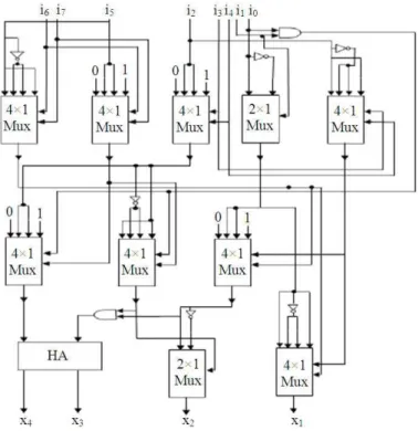
This structure is realized with the help of multiplexer in order to get the better result in terms of power dissipation and energy delay product. Figure 3, 4 and Table 1 shows the implementation of 8-4 and 9-4 compressors.
In a multiplexer, using the selection lines only the part of the structure is active, leaving the rest in idle mode. Thereby saving substantial amount of power and therefore reducing the energy delay product by many folds.
1.5. Multiplier Architecture
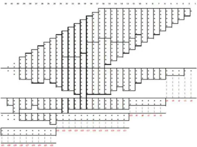
We have designed three different (8×8, 16×16 and 24×24) multipliers using Wallace tree architecture (Law et al., 1999). These multipliers uses higher order
compressors. Figure 5 shows architecture of a 16×16 multiplier. Different types of compressors are used to compute the partial product. Partial products are added in five stages. Proper pairs of compressors/adders have been used in order to reduce the vertical critical path. Let us consider column number fifteen of Fig. 5, which has fifteen dot products. We can use one 7-3 and 6-3 compressors and half adder to that column. This combination produces eight outputs. Instead of that, one 8-4 and 7-3 compressors could be a better option. This combination produces only seven outputs. By choosing proper combination of compressors/adders, we can minimize the critical path.
In Fig. 3 Vertical box indicates the compressors/adder. If any of the columns is not covered in the boxes, those products can be passed to the next stage. If the box is horizontal in direction, it indicates that the parallel adders have been used. We have used ripple carry adders in parallel adder. All three multipliers are designed very efficiently. We have designed the multiplier which has less number of adders/compressors. Now let us consider column 31 which has two vertical dots and column 32 which has one dot. Instead of using one half adders in column 31, we directly propagated those two dots into the next stages. This minimizes the number of adders in the multiplier.
1.6. Multiplier Performance and Comparison
Fig. 3. Implementation of 8-4 compressor using multiplexer
Marimuthu, R. et al. / American Journal of Applied Sciences 10 (8): 893-900, 2013
Fig. 5. Architecture of 16×16 bit multiplier
Fig. 6. Speed comparison of different multiplier
Fig. 8. Power comparison of different multiplier Table 1. Performance comparison of 8-4 and 9-4 compressors
8-4 Compressor 9-4 Compressor
--- --- Parameters Using full and half adder Using multiplexer Using full and half adder Using multiplexer
Power (nW) 18276-250 15263.603 21848.2180 15459.456
Delay (ps) 1028.000 1071.000 1082.0000 1077.000
Area (µm2) 93.139 110.779 102.1900 112.190
EDP 10−24 (J-s) 19.310 17.500 25.5779 17.931
Table 2. Delay, area and power comparison of different multipliers
Low Order Compressors Our Result
--- --- Multiplier type Delay (ns) Area ( m2) Power ( w) Delay (ns) Area ( m2) Power ( w)
8×8 2.84 1337.8 28.5 2.63 1273.6 31.6
16×16 4.60 5704.0 35.0 4.18 5677.2 41.2
24×24 6.50 12617.0 41.8 5.90 12653.0 46.0
2. CONCLUSION
Conventional multiplier uses low order compressors in the partial product reduction stage which provides uneven signal transition to the multiplier. Higher order compressors have been introduced to reduce the vertical critical path and also reduce the number of stages. Proposed compressors are designed with lesser number of gates. The proposed compressors give better results in terms of speed and area. Higher order compressor consumes more power than low order compressor and EDP of the higher order compressor is slightly higher than low order compressor. Using proposed structure one can make higher bit multiplications faster.
3. REFERENCES
Baran, D., M. Aktan and V.G. Oklobdzija 2010. Energy Efficient implementation of parallel CMOS multipliers with improved compressors. Proccedings of the international symposium on Low Power Electronics and Design, Aug. 18-20, IEEE Xplore Press, Austin, TX, USA., pp: 147-152.
Chang, C.H., J. Gu and M. Zhang, 2004. Ultra low-voltage low-power CMOS 4-2 and 5-2 compressors for fast arithmetic circuits. IEEE Trans. Circ. Syst., I: 1985-1997. DOI: 10.1109/TCSI.2004.835683 Dadda, L., 1976. On parallel digital multipliers. Alta
Marimuthu, R. et al. / American Journal of Applied Sciences 10 (8): 893-900, 2013
Dandapat, A., P. Bose, S. Ghosh, P. Sarkar and D. Mukhopadhyay, 2010. A 1.2 ns 16×16 bit binary multiplier using high speed compressors. Int. J. Electrical Comput. Syst. Eng., 4: 234-239.
Dandapat, A., P. Bose, S. Ghosh, P. Sarkar and D. Mukhopadhyay, 2007. Design of an application specific low-power high performance carry save 4-2 compressor. Proceedings of the IEEE VLSI Design and Test Symposium, (DTS’ 07), pp: 360-360. Gu, J. and C.H. Chang, 2003. Ultra low voltage, low
power 4-2 compressor for high speed multiplications. Proceedings of the International Symposium Circuits System, May 25-28, IEEE
Xplore Press, pp: 321-324. DOI:
10.1109/ISCAS.2003.1206267
Hsiao, S.F., M.R. Jiang and J.S. Yeh, 1998. Design of high-speed low-power 3-2 counter and 4-2 compressor for fast multipliers. Electron. Lett., 34: 341-343. DOI: 10.1049/el:19980306
Law, C.F., S.S. Rofail and K.S. Yeo, 1999. Low-power circuit implementation for partial-product addition using pass-transistor logic. IEE Proc. Circ. Devices Syst., 146: 124-129. DOI: 10.1049/ip-cds:19990328 Ma, M. and S. Li, 2008. A new high compression
compressor for large multiplier. Proceedings of the 9th International Conference on Solid State and Integrated Circuit Technology, Oct. 20-23, IEEE Xplore Press, Beijing, pp: 1877-180. DOI: 10.1109/ICSICT.2008.4734925
Ng, K.W. and K.T. Lau, 1999. An adiabatic 4-2 compressor design for low power VLSI. J. Circ.
Syst. Comput., 9: 339-339. DOI:
10.1142/S021812669900027X
Oklobdzija, V.G., D. Villeger and S.S. Liu, 1993. A method for speed optimized partial product reduction and generation of fast parallel multipliers using an algorithmic approach. IEEE Trans. Comput., 45: 294-306. DOI: 10.1109/12.485568 Oklobdzija, V.G., D. Villeger, S.S. Liu, 1996. A method
for speed optimized partial product reduction and generation of fast parallel multipliers using an algorithmic approach. IEEE Trans. Comput., 45: 294-306. DOI: 10.1109/12.485568
Prasad, K. and K.K. Parhi, 2001. Low-power 4-2 and 5-2 compressors. Proceedings of the Conference Record of the 35th Asilomar Conference on Signals Systems and Computers, Nov. 4-7, IEEE Xplore Press, Pacific Grove, CA, USA, pp: 129-133. DOI: 10.1109/ACSSC.2001.986892