Ahanchian Mohammad et alii,Frattura ed Integrità Strutturale, 13 (2010) 31-35; DOI: 10.3221/IGF-ESIS.13.04
31
Investigation of crack propagation in single optical fiber
composite with thermal influence by finite element method
Ahanchian Mohammad
Ph.D. Candidate of Mechanical Engineering, De La Salle University
Arzumanyan Hovhannes, Verlinski Sergey
Assistant Professor of Department of Mechanics and Machine Sciences, State Engineering University of Armenia
ABSTRACT. Two parallel comparative ‘Conventional Method and Computer Simulation using ANSYS software’
for prediction of crack growth and its behavior in optical fiber are studied and presented in this work. Corresponding finite element analysis was performed to determine the evolution of stress and strain states. The method is developed and combined with the modified J-integral theory to deal with this problem. The effects of crack length, temperature and mechanical forces are investigated by Finite Element Method in the cracked body. The conditions where the Mode I stress intensity factor motivate fracture occurrence is investigated and variations of the different cases are discussed. The most deleterious situation is found to be that wherein the entire model reaches rupture at some stage. The accuracy of the method is investigated through comparison of numerical results with computerized simulation using commercial ANSYS software.
KEYWORDS.Crack propagation; Fracture; Temperature loading; Stress intensity factor; Breaking force.
INTRODUCTION
Ahanchian Mohammad et alii,Frattura ed Integrità Strutturale, 13 (2010) 31-35; DOI: 10.3221/IGF-ESIS.13.04
32
element method is coded in MathCAD program to inspect fracture behavior and the results are compared with the ANSYS analysis. The effects of crack configurations, closure stresses and temperature on the failure load have also been investigated.
CONSTITUTIVE MODEL OF OPTICAL FIBER
he model of optical fiber is a composition of aluminum and silica glass as core which is developed within the framework of Small Static Displacement. The material properties are presented in Tab. 1. Two isotropic and homogeneous materials, joining to constitute a model of fiber optic in two-dimensional plane stress geometry with an initial circular crack on their meeting line are considered. According to the mentioned significance of optical fiber, ability of FEM and since computer modeling is useful to conduct virtual experiments with lower cost [7]; the authors decided to simulate a proper model on this design.
Material Density, Kg/m3
Modulus of Elasticity,
MPa
Modulus of
rigidity, MPa Poisson's Ratio
Thermal Conductivity,
W/m.K
Thermal expansion, 1/C
Glass 25400 46200 18600 0.245 6.21 8.00E-05
Aluminum 26600 71000 26200 0.334 237 2.36E-05
Table 1: Typical property of materials [8, 9].
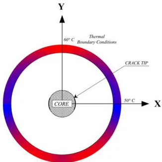
The diameter of optical fiber as standard is assumed to be 125 µm having a circular crack in the intersection line of two materials. Three different cases considering crack lengths of 3.5, 7 and 10.5 µm are investigated. In the first situation, the crack has the smallest length that is in two dimensional polar coordinate r (radius of crack tip) is equal to the radius of core and θ (angle between crack tip and X direction) had been assumed to be 15 degree. For other cases, radius had been kept constant and θ had been incremented by 15 degree in order to increase crack length. The problem is investigated in Linear Elastic Fracture Mechanics (LEFM) with Plane stress approach. Due to symmetry of the problem, a quarter segment of the model is analyzed. Boundary conditions are imposed such as horizontal line is constrained in Y direction and vertical line is constrained in X direction; both lines are considered as symmetric along their direction. Applied forces are imposed in X any Y directions with constant values and the breaking forces are calculated for each case. Thermal condition is assumed to have constant value in each half of the quarter model, the lower part of quarter model has 50 °C and the upper part has 60 °C in order to have thermal gradient as presented in Fig 1.
Figure 1: Applied forces and Thermal conditions on the model.
Ahanchian Mohammad et alii,Frattura ed Integrità Strutturale, 13 (2010) 31-35; DOI: 10.3221/IGF-ESIS.13.04
33
CONVENTIONAL FRACTURE ANALYSIS
o numerically predict crack formation and growth of this model under accidental loading, it is necessary to characterize fracture properties at the microscopic level. To approach this objective a complete code of program using finite element method was written by the authors in MathCAD software. The geometrical characteristics, material properties and boundary conditions are attributed to the model. Corresponding finite element analysis was performed to determine the evolution of stress and strain states. For more comprehensible results and better facileness for comparison Von Misses stress had been calculated across the model using Eq. (1).
(1)
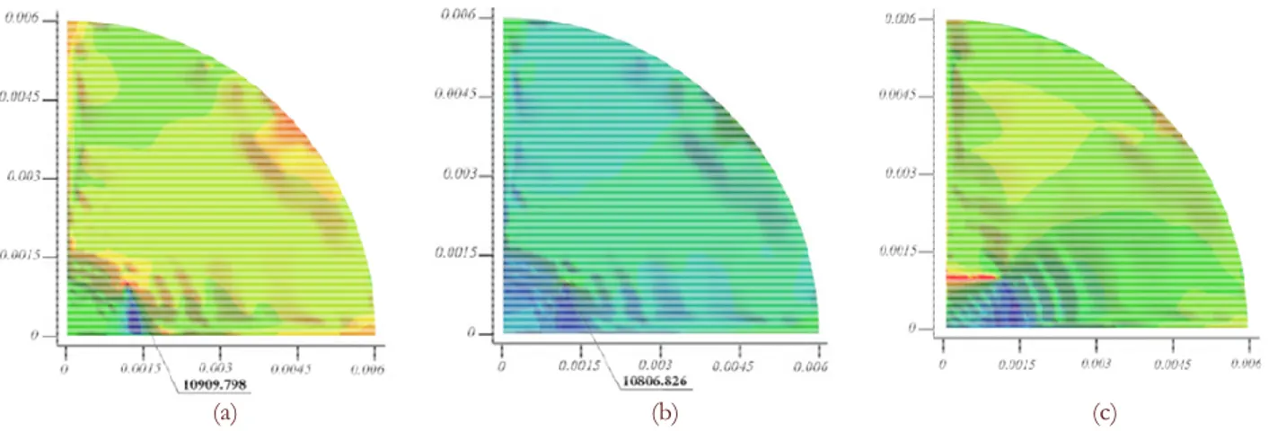
According to the theories in Fracture Mechanics, Stress Intensity Factor was calculated throughout the model and was applied to obtain J-integral. According to energy criterion, the critical energy release rate was determined and the crack extension was predicted and is presented in this paper. The breaking force values which lead the crack to propagate were obtained using Trial and Error Method for each case. The model will start propagation at low stresses and tends to extend at the tip of the crack [10, 11]. If the region be plastic at the tip of the crack, the metal mass around the crack would support the stress and the structure is not endangered [12]. Recent work on microstructure silica optical fibers indicated that they failed in a brittle manner and cracks initiated from the fiber surfaces [13]. According to the results, crack will propagate on the brittle area which is glass. The initiation and propagation of crack through brittle materials is at great speeds near the speed of sound [14]. Afterwards, thermal conditions were imposed and the complete procedure was done again. Based on the results, it is studied that crack will not growth anymore when the model is subjected to breaking force and thermal condition. Moreover, the largest crack needs less force to be broken. The contour plots for maximum crack length solved by MathCAD are presented in Fig 2. Fig 2.a shows Von Misses stress distribution subject to critical loading. Based on the data the highest amount of equivalent stress is placed near the crack tip. Fig 2.b presents Von Misses stress distribution subject to critical loading and thermal conditions. It is shown that the maximum amount of equivalent stress is decreased after applying thermal conditions which prevents crack propagation and material failure. The approximation of crack propagation subject to critical loading is illustrated in Fig 2.c.
(a) (b) (c)
Figure 2: Contour plots for maximum crack length (critical length), solved by MathCAD,
(a) Von Misses stress distribution subject to critical loading,
(b)Von Misses stress distribution subject to critical loading and thermal conditions,
(c) Approximation of crack propagation subject to critical loading.
The red region in Fig. 2.a shows the highest amount of equivalent stress. It is placed at the crack tip due to the fact that stresses concentrate at the crack tip. In Fig. 2.b the reduction of maximum amount of equivalent stress is a result of temperature. The prediction of crack propagation is presented by red region in Fig 2.c. It shows that crack will propagate in silica that is a brittle material meaning that it fractures rather than deforming plastically. It responses to increasing mechanical load until a slow-growing microscopic crack exceeds a certain threshold at which point the crack grows rapidly and the material fractures [3].
T
)
(
6
)
(
)
(
)
(
2
1
2 2 2 2 2 2zx yz xy x
z z
y y
x
eq
Ahanchian Mohammad et alii,Frattura ed Integrità Strutturale, 13 (2010) 31-35; DOI: 10.3221/IGF-ESIS.13.04
34
SIMULATION BY ANSYS
onsequently six different cases are discussed and each case is simulated by ANSYS to justify the accuracy of the written code in MathCAD. Some results are presented subsequently. The partial zoomed contour plots of ANSYS analysis of Von Misses stress distribution for the largest crack size subject to critical loading is presented in Fig 3.a. The result after imposing thermal condition to the previous situation is presented in Fig 3.b.
Figure 3: Zoomed contour plots for maximum crack length (critical length), simulated by ANSYS,
(a) Von Misses stress distribution subject to critical loading,
(b)Von Misses stress distribution subject to critical loading and thermal condition.
COMPARING THE RESULTS OF CONVENTIONAL METHOD AND ANSYS SIMULATION
n the first situation, the crack has the smallest length that is in two dimensional polar coordinate radius of crack tip is equal to the radius of core and the angle between crack tip and X direction had been assumed to be 15 degree. Critical force for this type of crack is -1.95 N; In this case maximum value for equivalent stress is 12.13 MPa, and is placed near the crack tip in Aluminum material. By adding thermal condition to applied force, maximum value for equivalent stress would be 12.02 MPa, which is lower than previous case.
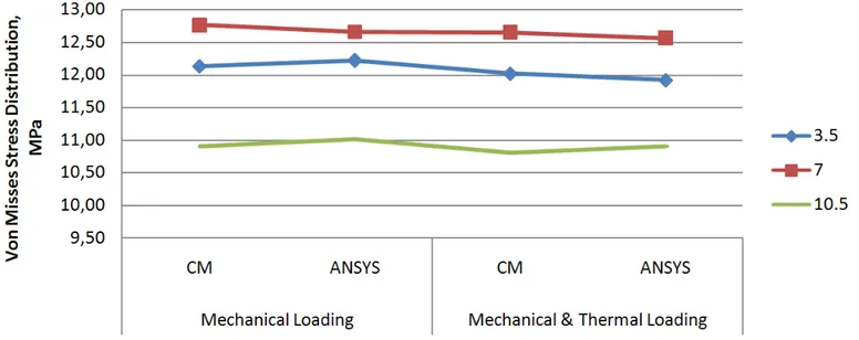
Figure 4: Comparison of maximum Von Misses stress in different cases.
C
Ahanchian Mohammad et alii,Frattura ed Integrità Strutturale, 13 (2010) 31-35; DOI: 10.3221/IGF-ESIS.13.04
35
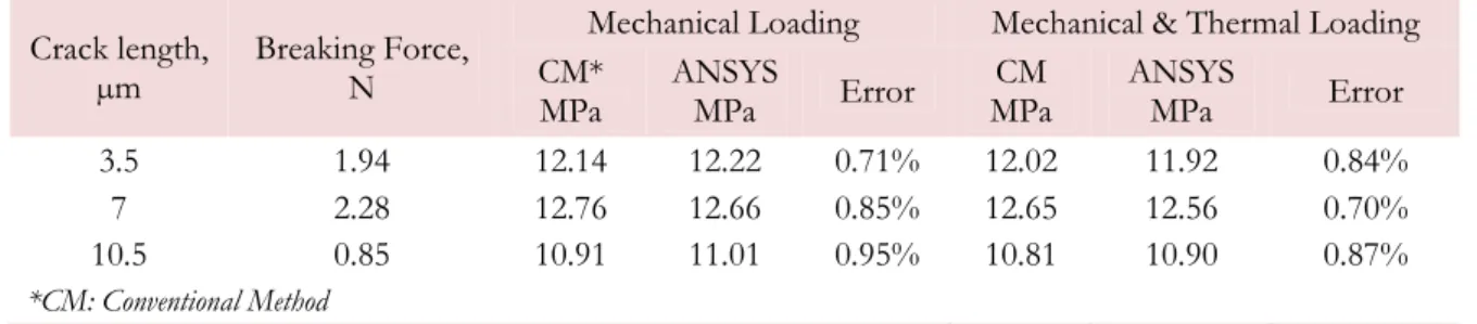
Maximum Von Misses stress and breaking force for different cases are presented in Tab. 2. The lowest amount of breaking force occurs in the largest crack size showing that we are near critical crack size. The value of stresses determine by conventional method and ANSYS simulation are presented and demonstrate that the differences are less than 1% which prove the accuracy of written code.
Crack length, µm
Breaking Force, N
Mechanical Loading Mechanical & Thermal Loading CM*
MPa
ANSYS
MPa Error
CM MPa
ANSYS
MPa Error 3.5 1.94 12.14 12.22 0.71% 12.02 11.92 0.84% 7 2.28 12.76 12.66 0.85% 12.65 12.56 0.70% 10.5 0.85 10.91 11.01 0.95% 10.81 10.90 0.87% *CM: Conventional Method
Table 2: Maximum Von Misses stress distribution and breaking force for different cases.
CONCLUSION
he computational results presented in this research demonstrate the capabilities of the energy criterion towards modeling fracture in microstructure composites such as optical fiber. Critical forces in each case are obtained and it is clear that applying temperature condition would prevent the fracture process and fracture occurs under higher stresses as a result the optical fiber should be protected from low temperatures by adding cladding. It also protects from mechanical loading. Moreover, Prediction of crack branching and propagation is summarized and compared. The maximum stress magnitudes which instigate the crack are presented and compared. This shows that how big mechanical loading could our design withstand. Consequently, there are some parameters that mitigate crack propagation which are higher temperature, lower stresses and smaller grain size. This theory is a result of investigation by conventional method. When the temperature increases, a higher stress is required for a crack to propagate. Another point is that large crack size with 45 degree, is critical length and crack propagation occurs under minimum value of mechanical force and shows that production control should be improved properly.
REFERENCES
[1] S. B. Grassino, What is Optical Fibers Made of?, University of Southern Mississippi (2003). [2] R. Paschota, Journal of Optik & Photonik, 2 (2008).
[3] A. D. Yablon, “Optical Fiber Fusion Splicing” (2005) 181.
[4] R. Bai, C. Yan, 5th Australasian Congress on Applied Mechanics, ACAM 2007.
[5] C. Yan, R.X. Bai, P. K.D.V. Yarlagadda, H. Yu, 9th Global Congress on Manufacturing and Management (GCMM
2008) Surfers Paradise, Australia.
[6] C. P. Chen, T. H. Chang, Journal of Materials chemistry and physics, ISSN 0254-0584, 77 (1) (2003) 110. [7] O. C. Zienkiewicz, R. L. Yaylor, The Finite Element Method, Forth ed., McGraw-Hill (1994).
[8] F. P. Incorpera, D. P. Dewitt , Introduction to Heat Transfer, Translation of Third Edition Isfahan University,1 (2003).
[9] J. E. Shigley, C. R. Mischke, Mechanical Engineering Design, Tehran (2001).
[10]D. A. Anderson, J. C. Tannehill, R. H. Pletcher, Fracture Mechanics, Hemisphere, Washington, DC (1984). [11]C. Atkinson, F. G. Leppington, Int. J. Solids Struct., 13 (1977) 1103.
[12]http://www.pdhcenter.com/courses/m155/m155.pdf, ‘Brittle Fracture Mechanism’, DOE-HDBK-1017/2-93 Brittle Fracture.
[13]C. Yan, X. D. Wang, L. Ye, K. Lyytikainen, J. Canning, The 18th Annual Meeting of the IEEE, Lasers and
Electro-Optics Society LEOS 2005, 529.
[14]G. P. Cherepanov, Mechanics of Brittle Fracture, McGraw-Hill, New York (1979).