K. G. Kodancha et alii, Frattura ed Integrità Strutturale, 8 (2009) 45-51; DOI: 10.3221/IGF-ESIS.08.04
45
Variation of stress intensity factor and elastic T-stress
along the crack-front in finite thickness plates
K. G. Kodancha, S. K. Kudari
Department of Mechanical Engineering, B. V. B. College of Engineering & Technology, Hubli 580 031, India
ABSTRACT. Non-singular terms in the series expansion of the elastic crack-tip stress fields, commonly referred
to as the T-stress. The T-stress is as an additional stress field characterizing parameter to stress intensity factor (K) in the analysis of cracked bodies. T-stress is used as an important constraint parameter in the fracture analysis. In this investigation, three-dimensional finite element analyses have been conducted to compute the elastic T-stress considering a single edge notched tensile (SENT) specimen with varied thickness and a/W ratio. The results indicate that the T-stress depends on the specimen thickness and significantly varies along the crack-front from surface to centre of the specimen. The T-stress results obtained in the present analysis together with corresponding KI values can be used for analysis of constraint effects in a fracture specimen.
KEYWORDS: Elastic T-stress; Stress intensity factor; Finite element method; Constraint issue.
INTRODUCTION
he elastic T-stress, or the second term of the Williams [1] series expansion for linear elastic crack-tip fields, represents the stress acting parallel to the crack plane. The T-stress can strongly affect the magnitude of hydrostatic triaxiality in the near crack-tip elastic–plastic fields. It is well known that the sign and magnitude of stress can substantially alter the level of crack-tip stress triaxiality [2-4], hence influence crack-tip constraint. Positive T-stress strengthens the level of crack-tip T-stress triaxiality and leads to high crack-tip constraint; while negative T-T-stress reduces the level of crack-tip stress triaxiality and leads to the loss the crack-tip constraint. Several researchers [5-8] have shown that the T-stress, in addition to the K or J-integral, provides an effective two-parameter characterization of plane strain elastic–plastic crack-tip fields in a variety of crack configurations and loading conditions. The application of two-parameter fracture mechanics to include the constraint effect in the failure assessment procedure is becoming more and more established. In order to apply the two-parameter fracture mechanics methodology, it is important to provide T-stress solutions for the crack configuration under consideration. Many earlier investigators [9, 11] have provided T-T-stress solutions for 2D cracked bodies. However, study on variation of T-stress along the crack-front is very limited. Recently, Qu and Wang [12] using quarter-elliptical corner cracks have shown that the magnitude of T-stress varies along the quarter-elliptical corner crack-front. But dependence of T-stress along the crack-front in fracture specimens is not available. Hence, in the present investigation, detailed three-dimensional finite element analyses have been conducted to study the variation of the T-stress and KI along the crack-front considering a SENT specimen geometry having varied thickness and crack length to width ratio (a/W) subjected to tension load.
FINITE ELEMENT ANALYSIS
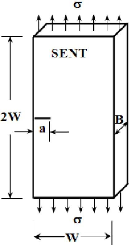
series of 3D stress analyses by finite element method have been made on SENT specimen using ABAQUS 6.5 [13] finite element software. The geometry of the specimen considered in this analysis is shown in Fig.1. Finite element computations were carried out considering only one half of the specimen due to the symmetry. The analysis domain is descritized using 20-noded isoparametric 3D solid reduced integration elements. These types of
T
K. G. Kodancha et alii, Frattura ed Integrità Strutturale, 8 (2009) 45-51; DOI: 10.3221/IGF-ESIS.08.04
46
elements in ABAQUS are referred as C3D20R. This kind of elements is used in the work of Qu and Wang [12] for computation of T-stress. In this analysis, to model the (1/ r ) singularity of stress/strain at the crack-front, the nodes of crack front elements are shifted to quarter point as shown in Fig.2. The number of elements in the analysis domain varied with the thickness of the specimens. It is noted that for specimen with thickness 2 mm the number of elements used are 5625 (number of nodes, 25,536) and for 20 mm thick specimen the number of elements used were 7875 (number of nodes, 35, 456). The number of elements in the analysis domain increases with increase in the specimen thickness to maintain the mesh refinement. For specimen with thickness between 2 and 20 mm the numbers of elements were between 5625 – 7875. A typical mesh used in the analysis is shown in Fig.3. The stress distribution and the magnitude of KI and T-stress were obtained by ABAQUS post processor. The method of computation of KI and T-stress from ABAQUS are detailed in the following section. The variation of stress components, T-stress and KI along the crack-front has been studied for varied specimen thickness and crack length to width ratio (a/W=0.4-0.6). The normal stress () applied on the specimen as shown in Fig.1 is considered = 50 MPa, which is ≈1/3rd of yield stress to keep the analysis domain approximately under LEFM. The specimen thicknesses (B) considered in this analysis are 2 to 20 mm (B/W=0.1-1.0) in steps of 2 mm. In these calculations, the material considered is interstitial free steel (IF) possessing yield strength (y) of 155 MPa and elastic modulus of 197 GPa [14].
Computation of KI andT-stress
The computation of stress intensity factor (KI) is carried out by maximum tangential stress criterion [15] as available in ABAQUS. The T-stress extracted by ABAQUS post processor is as given below.
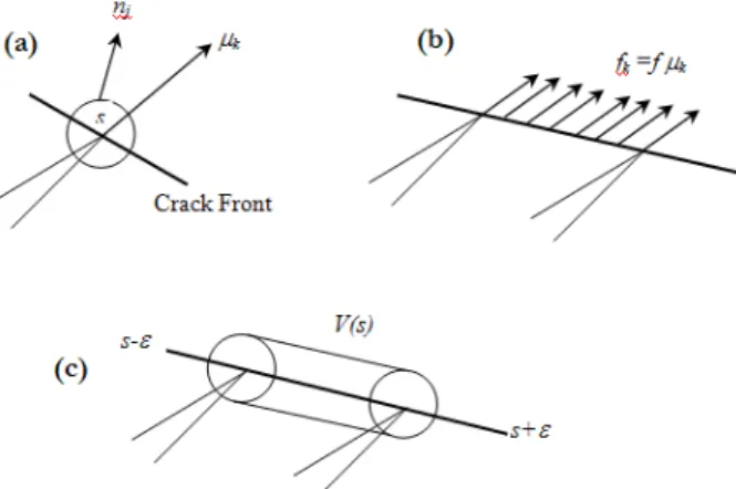
Consider a 3D crack front with a continuously turning tangent as shown in Fig. 4a. Assume a line-load of magnitude fk =
fk(s) to be applied along the crack front as illustrated in Fig. 4b. In the figure, k(s) defines the direction normal to the crack front and in the plane of the crack at point s. The solution for this problem is the case of a plane strain semi-infinite crack with a point force f applied at the crack tip in the direction parallel to the crack. Using superscript ‘L’ to designate the stress and displacement fields, the analytical solution [16] gives:
Stress field:
s q
p
= 3
11 cos ,
L f
r s =p q q 2 22 cos sin ,
L f
r s33 =p ncos ,q
L f
r
s13L =s23L =0 s q q
p
= 2
12 sin cos ,
L f
r (1)
and displacement field :
n q
p n
ì æ ö ü
ï ï
- ï ç ÷ ï
= íï ç ÷çè ø÷+ - ýï
ï ï î þ 2 2 1 1 sin ln 2(1 )
L f r
u
E d
{
}
n n q q q
p +
= -
-2 1
(1 2 ) cos sin 2 L f u E = 3 0 L u (2)
Employing the stress field and displacement field solutions given in Eqns. (1) and (2) as an auxiliary field, Kfouri [17] has
extracted the T-stress for 2D crack problems by introducing an interaction J-integral. Nakamura and Parks [18] extended this method of extraction of T-stress to 3D crack problems and provided the domain integral formulations in the form given below:
s s s e
ìæ ö ü
ï ¶ ¶ ÷¶ ¶ ï
ïç ÷ ï
= íïççç ¶ + ¶ ÷÷¶ - ¶ ýï
è ø ï ï î þ
ò
( ) 1 ( ) L L Li i k k ij ij ij ij cV s k k j k
u u q q
I s dV
A x x x x (3)
where V(s) is a domain, which encloses the crack front segment between (s-) and (s+) (refer Fig. 4c), qk(s) defines the
K. G. Kodancha et alii, Frattura ed Integrità Strutturale, 8 (2009) 45-51; DOI: 10.3221/IGF-ESIS.08.04
47
crack advance; ij, ij and ui are the stress, strain and displacement components of the 3D crack problem under
consideration; sijL, e
L ij and
L i
u are the corresponding components in the line-load auxiliary solution given by Eqns. (1) and (2).
Nakamura and Parks [18] have shown that the crack-tip T-stress is related to the integral, I(s) as given below:
ne u
ì ü
ï ï
ï ï
= - íï + ýï
ï ï
î 33 þ
2 ( )
( ) ( )
1
E I s
T s s
f (4)
where 33(s) is the extensional strain at point s in the direction tangential to the crack front.
The computation of the domain integral, Eqn. (3), is readily compatible with finite element formulations. In this analysis, T-stress is computed from Eqn. (4) based on the domain integral I(s) (refer Eqn. (3)) using five contours. In this Finite element analysis it is observed that last four contours give almost path independent values of I(s). Hence, in this study, the average value of T-stresses is obtained using the results from the outer four contours.
Figure1: Geometry of the specimen considered in the analysis.
K. G. Kodancha et alii, Frattura ed Integrità Strutturale, 8 (2009) 45-51; DOI: 10.3221/IGF-ESIS.08.04
48
Figure 3: A typical Finite element mesh used in the analysis.
Figure 4: A schematic diagrams of elements used in the definition of the interaction integral:
(a) crack front and contour, (b) line load applied along the crack front and (c) volume V(s) encloses the crack front segment.
RESULTS AND DISCUSSION
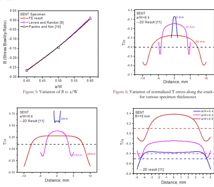
nitially, two dimensional elastic plane stress FE analysis is conducted on the SENT specimen with a/W=0.4, 0.5 and 0.6 and applied load 50 MPa for validation of 2D T-stress results obtained in the present study with results available in the literature [9,10]. The T-stress values are converted to bi-axial stress (B) from the relation:
s =
I
T a
B
K (5)
K. G. Kodancha et alii, Frattura ed Integrità Strutturale, 8 (2009) 45-51; DOI: 10.3221/IGF-ESIS.08.04
49
of crack-tip plasticity. The magnitude of normalized T-stress for SENT specimen (a/W=0.5) obtained in 2D analysis reported by Sherry et al. [11] is -0.4 (shown by dotted line in Fig.6). In the present 3D analysis it is found that normalized stress for specimen having a/W=0.5, varies between -0.6 to -0.1 depending on the thickness of the specimen. As T-stress is used as constraint parameter, this result demonstrates that the constraint parameter is not a unique value; it varies along the thickness of the specimen. It is known that the magnitude of T-stress depends on the a/W ratio [11] of the specimen. The 2D results of Sherry et al. [11] shows that normalized T-stress is positive (0.1) for a/W=0.6. The FE results of variation of T-stress along the thickness of specimen with a/W =0.6 along with 2D results [11] is shown in Fig.7. It is interesting to know from this figure that the T-stress is negative on the surface of the specimens with higher thickness and vice versa.
Figure 5: Variation of Bvs. a/W Figure 6: Variation of normalized T-stress along the crack-front for various specimen thicknesses
Figure 7: Variation of normalized T-stress along the crack-front for various specimen thicknesses.
Figure 8: Variation of normalized T-stress along the crack-front for various a/W ratio and specimen thickness 10 mm.
A typical variation of normalized T-stress (T/) along the crack-front for various a/W ratio and specimen thicknesses 10 mm along with 2D result [11] is shown in Fig.8. This figure shows the effect of a/W ratio on variation of T-stress along the crack-front. This analysis demonstrates that the studies on constraint issues based on T-stress estimated by 2D analysis leads to considerable error. Hence, it is required to conduct 3D analysis to completely assess the constraint issues in a fracture specimen having finite thickness.
K. G. Kodancha et alii, Frattura ed Integrità Strutturale, 8 (2009) 45-51; DOI: 10.3221/IGF-ESIS.08.04
50
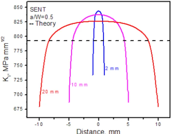
Fernandez et al. [19]. The effect of variation of KI for specimens with a/W=0.4, 0.5 and 0.6 are also studied. A typical plot of effect of a/W ratio on variation of KI for specimen thickness 10 mm is shown in Fig.10. This figure illustrates that the nature of variation of KI along the crack-front is almost similar for various a/W ratios. But, the magnitude of difference in KI (KI) estimated by 2D and 3D analyses measured at the centre of the specimen thickness is found to vary with respect to specimen thickness. For the similar applied load it is observed that (KI) is higher for a/W=0.6, which indicates that the specimen experience high crack-tip constraint at the centre than other specimens with a/W < 0.6.
The T-stress results obtained in the present analysis together with corresponding KI values can be used for analysis of constraint effects in a fracture specimen. The 3D results indicate that the magnitude of T-stress and KI are lesser on the surface than the centre of the specimen. Compared to 2D results one can infer from these results that the crack-tip constraint is very high at the centre of the specimen than at the surface. The constraint effect on the surface is referred as in-plane constraint and at the centre is referred as out of plane constraint [20]. Due to higher out of plane constraint the material at the centre of the specimen thickness fails earlier than on the surface. The constraint also depends on the specimen a/W ratio. The present results infer that the specimen with higher a/W ratio experiences highest crack-tip constraint. The 3D results obtained in this study can also be used to formulate/correct two parameter characterization of crack-tip fields proposed by Betegon and Hancock [5].
Figure 9: Variation of KI along the crack-front for various
specimen thicknesses.
Figure 10: Variation of KIalong the crack-front for various a/W
ratio and specimen thickness 10 mm.
CONCLUSIONS
ollowing conclusions are made from the present study:
- The magnitude of T-stress and KI varies along the crack-front; the variation depends on the specimen thickness and a/W ratio of the specimen.
- Crack-tip constraint is very high at the centre of the specimen than at the surface because of higher magnitude of T-stress and KI at the centre of the specimen.
- Due to higher out of plane constraint the material at the centre of the specimen thickness fails earlier than that on the surface.
ACKNOWLEDGEMENT
uthors gratefully acknowledge the computational facilities provided by Research Center, B. V. B. College of Engineering & Technology, Hubli, and ProSim, Bangalore.
F
K. G. Kodancha et alii, Frattura ed Integrità Strutturale, 8 (2009) 45-51; DOI: 10.3221/IGF-ESIS.08.04
51 REFERENCES
[1] M. L. Williams, ASME Journal of Applied Mechanics, 24 (1957) 109–114.
[2] S. G. Larsson, A. J. Carlsson, Journal of Mechanics and Physics of Solids, 21 (1973) 263–277. [3] J. R. Rice, Journal of Mechanics and Physics of Solids, 22 (1974) 17–26.
[4] B. A. Bilby, G. E. Cardew, M. R. Goldthorpe, I. C. Howard. Size Effect in Fracture. London: Mechanical Engineering Publications Limited, (1986) 37–46.
[5] C. Betegon, J. W. Hancock, ASME Journal of Applied Mechanics, 58 (1991) 104–110. [6] Z.Z. Du, J.W. Hancock, Journal of Mechanics and Physics of Solids, 39 (1991) 555–567. [7] N. P. O_Dowd, C. F. Shih, Journal of Mechanics and Physics of Solids, 39 (1991) 989–1015. [8] Y. Y. Wang, ASTM STP, 1171. American Society for Testing and Materials, (1993), 120–38. [9] P.S. Levers, J.C. Randon, International Journal of Fracture, 19 (1982) 311-325.
[10] G.H.Paulino, J.H.Kim, Engineering Fracture Mechanics, 71 (2004) 1907-1950.
[11] A.H. Sherry, C.C. France, L. Edwards, Fatigue and Fracture of Engineering Materials and Structures, 18 (1995) 141-155.
[12] Jie Qu, Xin Wang, International Journal of Pressure Vessels and Piping, 83 (2006) 593–606. [13] ABAQUS User’s Manual. Version 6.5. Hibbitt, Karlsson & Sorensen, Inc., (2004).
[14]. S.K. Kudari, Ph.D thesis, (2004), IIT, Kharagpur, India.
[15]. F. Erdogan, G. C. Sih, Journal of Basic Engineering, 85 (1963) 519-527. [16]. S. P. Timoshenko, J.N. Goodier, Theory of elasticity, McGraw-Hill (1970). [17]. A. P. Kfouri, International Journal of Fracture, 30 (1986) 301–315.