Ceramics – Silikáty 55 (4) 305-311 (2011) 305
TRIBOLOGICAL PROPERTIES OF TiB
xAND WC/C COATINGS
#
FRANTIŠEK LOFAJ1,2
, MARIAN MIKULA3,4, BRANISLAV GRANČIČ4
, GREGORZ CEMPURA5 , PETER HORŇÁK1, PETER KÚŠ4, DANIEL KOTTFER6
1Institute of Materials Research of SAS, Watsonova 47, 040 01 Košice, Slovakia 2
Faculty of Materials Science and Technology in Trnava, Slovak University of Technology in Bratislava, Paulínska 16, 916 24 Trnava, Slovakia
3Institute of Materials and Machine Mechanics of SAS, Račianska 75, 831 02 Bratislava, Slovakia
4Faculty of Mathematics, Physics and Informatics, Comenius University in Bratislava, 842 48 Bratislava 4, Slovakia
5Faculty of Metals Engineering and Industrial Computer Science, AGH University of Science and Technology, Al. A. Mickiewicza 30, PL-30059 Kraków, Poland
6
Faculty of Mechanical Engineering, Technical University of Košice, Mäsiarska 74, 040 01 Košice, Slovakia
#E-mail: lofaj@imr.saske.sk
Submitted June 23, 2011; accepted September 26, 2011
Keywords: Coeficient of friction, Thin nanocomposite coatings, TiB2, WC/C, Transfer ilm
Tribological properties of TiBx and WC/C coatings have been studied using the ball-on-disc method at room and elevated
temperatures in air to investigate their behavior under conditions approaching high performance dry cutting. The average room temperature coeficients of friction (COF) of both nanocomposite DC magnetron sputtered TiBx coatings and PECVD
WC/C coatings were in the range 0.2-0.6. The lowest value of TiBx coatings of 0.16 was achieved in case of prefferentially
oriented stuctures deposited at the highest negative bias. The lowest COF of WC/C was around 0.11. The increase of testing temperature to 450°C caused the increase of COF up to approximately 0.7-0.8. The experiments at elevated temperatures suggest the existence of the oxide transfer ilm with higher COF than that of the sliding contact without the ilm. Although both coating systems have relatively high COF values at elevated temperatures, they exhibit elements of some adaptive behavior.
INTRODUCTION
Dry machining under high stress and temperature in the oxidizing air atmosphere results in excessive wear of the cutting tools, which limits their lifetime and reduces effectiveness of the whole machining process. Productivity increase requires higher machining speeds and longer lifetime of cutting tools. However, higher speeds enhance wear and all other negative factors. Obviously, new materials for inserts and/or coatings with better wear and corrosion resistance have to be utilized. The possibility of adapting to the conditions is one of the principal solutions in the coating ield besides introduction of coatings with improved hardness and better friction properties [1-5]. The main idea of adaptability of the coatings is that the structure, composition and properties of the coating automatically change according to the external conditions to minimize friction [1-6]. Adaptability may take place either due to formation of stable protective oxide layers or high temperature lubricious oxides or by a combination of both mechanisms [7-8]. Typically, tribo-oxidation is the process controlling friction and the nanoscale triboilms developed at the friction contact dynamically
destroy and form providing protection and lubrication. Adaptive coatings were originally developed on oxide/ dichalcogenide systems (e.g. ZnO/MoS2, PbO/MoS2,
ZnO/WS2) and later extended toward nanocrystalline
carbides (TiC, WC), diamond-like carbon (DLC), oxide (YSZ, AlON)) and other (e.g. MoS2, WS2) systems [1-6].
Using intrinsically hard materials for coatings is another possibility for obtaining properties desirable for high speed cutting. The examples include diamond and DLC coatings, TiBx coatings etc. The third approach
Lofaj F., Mikula M., Grančič B., Cempura G., Horňák P., Kúš P., Kottfer D.
nanocrystalline structure, highly non-equilibrium state, high oxidation stability, high hot hardness and improved plasticity [10-11]. The adaptability of these coatings can be further improved by an introduction of multi-nanolayers that could be transformed into the triboilms with enhanced lubricity. In the quaternary coating system TiAlCrN/WN containing multiple WN nanolayers, adaptive behavior led to coeficient of friction (COF) reduction from 0.1 to 0.06 and only a half of the lank wear [3]. The result was attributed to the formation of WO-triboilm with low shear strength. It results in COF reduction which subsequently lowers the cutting forces and heat generation and subsequently causes overall wear reduction and tool lifetime prolongation.
The same principles as in nitride systems can be applied to other systems based on carbides and/or borides. For instance, nanostructured TiB2, CrB2 and ZrB2 layers
with the addition of Al, Si, N are stable up to 900°C [12]. Our studies on nanocomposite WC–C coatings revealed hardness up to 28 GPa and the minimum COF for dry friction at room temperature around 0.1. However, COF rapidly increased at elevated temperatures due to formation of unstable WO-based triboilm [13-14], which is contrary to the observation of the role of WO ilms originating from WN. Therefore the aim of this work is more detailed investigation of TiBx and WC–C
coatings in order to understand the possibilities and limitations of these systems for adaptive behavior.
ExPERIMENTAL
The studied nc-WC/a-C coatings were deposited on polished tempered and annealed tool steel (STN 412050). WC/C coatings with the thickness of around 500 nm have been deposited using PECVD process when tungsten carbonyl decomposed in a vacuum chamber in a glow discharge plasma. Deposition parameters included total and partial pressures of various carrier gases in the chamber, current density and bias voltage applied to the substrate [13-15].
TiBx coatings were deposited on polished steel
substrates using unbalanced DC magnetron sputtering with different negative substrate bias voltage, Us [16].
The substrates were left on loating potential (-14 V) or biased negatively with Us = -50 V and Us = -100 V.
The wavelength dispersive electron probe microanaly-ses (WDS, Inca Wave, Oxford Instruments Analytical) showed excess of B and the overstoichiometric concen-tration ratio B/Ti decreased from 2.9 to 2.4 when negative bias increased from Us = -14 V to Us = -100 V.
The microstructure of both types of coatings was investigated using transmission electron microscope (model JEOL JEM-2010ARP) on lamellas prepared by focused ion beam (FIB) (model Zeiss, NEON 40EsB CrossBeam).
The indentation hardness, HIT, of TiBx coatings was
measured using nanoindenter Hysitron TI 750 UBI with
Ceramics – Silikáty 55 (4) 305-311 (2011) 307
a Berkovich indenter at the constant indentation depth of 120 nm. Each test was repeated 9 times in order to minimize the experimental errors.
The ball-on-disc method using high temperature tribometer (model THT, CSM, Switzerland) was used to investigate tribological properties of the coatings. The counterface of the coatings was a 100Cr6 steel ball with a diameter of 6 mm. Friction behavior was investigated in air at room temperature and at 450°C under the load
of 0.5 N, with the sliding distance up to 100 m. Sliding rates were in the range from 5 cm/s up to 30 cm/s at room
temperature and 15 cm/s at 450oC. The corresponding
wear track radii were in the range from 3 mm up to ~10 mm. Friction coeficient and the penetration depth were continuously recorded in each test as a function of total sliding distance. Total sliding distance is relevant to the wear of the ball because of permanent contact with the coating during the test. However, friction coeficient is plotted mostly as a function of total distance for easier comparison with the literature data. Wear tracks were observed by optical microscopy and scanning electron microscopy combined with energy dispersive X-ray spectroscopy.
RESULTS AND DISCUSSION
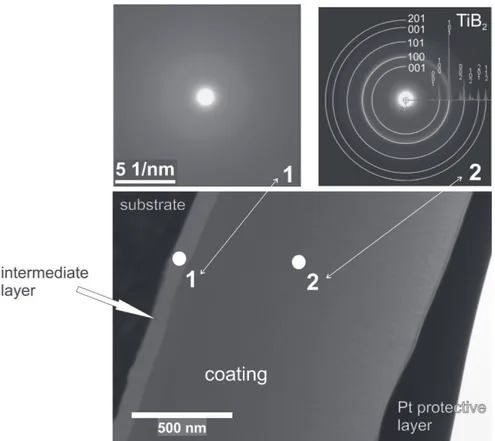
Microstructure of TiBx coating and selected area
electron diffraction (SAED) patterns from the coating and intermediate layer areas are shown in Figure 1. The coating thicknes was about 1.1 µm and the thickness of the intermediate layer was around 100 nm. The electron diffraction analysis revealed nanocrystaline structure of the coating. It consisted of TiB2 (hexagonal) phase
and amorphous structure in area of intermediate layer. HRTEM investigations conirmed the presence of nanocrystals within the coating with size in the range between 2 and 7 nm. [19]
Analogous investigations were performed on the studied WC-C coatings. Figure 2 shows the micro-structure of the WC-C coating and corresponding SAED patterns. The thickness of the coating was found to be about 500 nm. The analysis of diffraction patterns indicated the presence of WC0.82 (face-centered cubic)
phase within the coating. The ring character of electron diffraction pattern suggested small grain size of WC0.82
phase.
Figure 2. TEM image of the microstructure of WC–C coating with the corresponding SAED pattern obtained from FIB lamella.
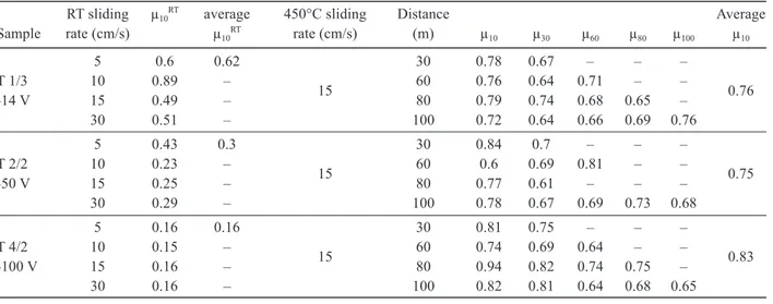
Table 1. Summary of the tribological tests at RT and 450°C on TiBx system.
RT sliding µ10RT average 450°C sliding Distance Average
Sample rate (cm/s) µ10RT rate (cm/s) (m) µ10 µ30 µ60 µ
80 µ100 µ10
5 0.6 0.62 30 0.78 0.67 – – –
T 1/3 10 0.89 – 60 0.76 0.64 0.71 – –
-14 V 15 0.49 – 15 80 0.79 0.74 0.68 0.65 – 0.76
30 0.51 – 100 0.72 0.64 0.66 0.69 0.76
5 0.43 0.3 30 0.84 0.7 – – –
T 2/2 10 0.23 – 60 0.6 0.69 0.81 – –
-50 V 15 0.25 – 15 80 0.77 0.61 – – – 0.75
30 0.29 – 100 0.78 0.67 0.69 0.73 0.68
5 0.16 0.16 30 0.81 0.75 – – –
T 4/2 10 0.15 – 60 0.74 0.69 0.64 – –
-100 V 15 0.16 – 15 80 0.94 0.82 0.74 0.75 – 0.83
Lofaj F., Mikula M., Grančič B., Cempura G., Horňák P., Kúš P., Kottfer D.
Figure 3 shows COF as a function of sliding
dis-tance measured at room temperature (RT) at different
sliding rates in TiBx coating deposited with the bias of
-100V. COF values stabilized after very short running-in period of 1 m at the level of 0.15 - 0.16. The coatings deposited at smaller and zero bias exhibited higher COF values and less favorable behavior. A plateau in the range 0.2-0.4 was sometimes observed up to 5 m sliding distance and then, COF usually increased depending on the sample and sliding speed up to 0.5-0.6 at 10 m of sliding distance. The results of the tests at room temperature are summarized in Table 1. The increase of COF at small distance is often only apparent due to different number of passes when different track radii are used. However, it can be attributed to faster wearing out of the coating and reaching ball-to-substrate contact at longer distances.
The lowest COF in case of the largest negative bias
Us= -100V can be related to the presence of strong (0001)
textured nanostructure, whereas randomly ordered nanostructures developed at lower substrate bias exhibit higher COF-s [16]. Similar tendency was observed in case of hardness: HIT up to 56 GPa was obtained in
prefferentially oriented (0001) nanostructure and it was reduced to 45 GPa and 37 GPa for the samples deposited
at Us of -50 V and -14V, respectively, as the level of
textured orientation decreased.
All the data obtained at elevated temperature
(450oC) exhibited behavior which was different from
that at RT: COF increased and signiicant scatter compa-red to RT measurements were observed in all cases (Figure 4). The initial period of the curve is characteri-zed by relatively high friction coeficient in the range of 1-1.4. COF drops to approximately 0.7 after several
Figure 3. Room temperature dependence of the coeficient of friction on the sliding distance at different sliding rates.
sliding distance (m)
TiB2, sample 3-1 RT, 0.5 N
C
O
F
0 0.06 0.08 0.10 0.12 0.14 0.16 0.18
1 2
30 cm/s
15 cm/s 5 cm/s
10 cm/s
3 4 5 6 7 8 9 10
Figure 4. COF vs. sliding distance at 450°C in case of TiBx sample 1-3.
sliding distance (m)
TiB2, sample 1-3 10 cm/s, 450°C
C
O
F
0 0.6 0.7 0.8 0.9 1.0 1.1 1.2 1.3 1.4
10 20 30 40 50 60 70 80 90 100
Table 2. Summary of the COF in the regime of stable friction at the sliding distance of 10 m and the corresponding deposition conditions in WC–C coatings.
Atmosphere: Total pressure/current density
Sample Average COF at 10 m Precursor +... (Pa)/(mA/cm2
)
WC9 0.17 – 2/0.8
WC14 0.14 – 3/0.8
WC15 0.13-0.14 – 3/1
WC18 0.19 – 2/1
WC28 0.20-0.24 – 2/1
WC29 0.72-0.81 – 1/1
WC12 0.13-0.14 Ar 3/0.8
WC27 0.16-0.20 Ar 2/1
WC26 0.11-0.20 N2 2/1
WC20 0.66 (0.53-0.70) H2 4/1.3
WC21 0.19(0.19-0.23) H2 3/1
WC22 0.15 (0.13-0.18) H2 2/1
WC23 0.18 (0.16-0.19) H2 1/1
WC25 0.18-0.25 H2 2/1
WC16 0.17 C2H2 3/1
WC17 0.15-0.16 C2H2 4/1
WC19 0.51 (0.49-0.55) C2H2 4/1.3
Ceramics – Silikáty 55 (4) 305-311 (2011) 309
meters of sliding and then oscilates within the range 0.6-0.7 up to 100 m. The repeated tests under the same conditions conirmed high reproducibility of this behavior in most of the coatings. Although the running-in period is less pronounced or absent, similar running-inal COF values were typical also for the coating with the lowest RT COF (see Figure 3). Figure 5 suggests negligible effect of different radii (3, 4, 5 and 6 mm), the curves overlap within the measured experimental scatter and COF is around 0.7.
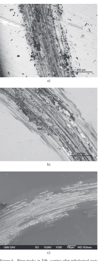
Optical microscopy observation of the wear tracks indicated variations in the extent of the coating damage corresponding with the COF values. Wear tracks in the coating T 3/3 having low COF (Figure 6 a)) show little damage compared to that in Figure 6 b) in terms of width and the surface area of steel substrate exposed (grey area) and exceeding the difference in sliding distance. The appearance of the wear tracks suggests that at shorter distances wear occurs by means of adhesive mechanism with gradual removal of the coating. SEM observation at larger magniication (Figure 6 c)) suggests smearing of the surface layer and/or transition layer formation accompanied by local abrasion, chiping out of the coating and debris formation at the track sides occur. Additional energy dispersive X-ray microanalysis indicated an increase of oxygen in the worn layer. Thus, the possibility of the formation of a thin transition layer composed of the corresponding oxides in the tribological contact has to be considered.
Table 2 summarizes the results of tribological tests and deposition conditions in WC/C system. The values of COF during stable regime were in the range from 0.11 to 0.80 and varied depending on the deposition conditions. The increase of the working pressure resulted in lower COF within each set. The optimum value of the pressure was around 3 Pa and it is related more to higher pressure of the precursor vapors than to total pressure and or additional gas. The effect of additional gases is clearly demonstrated on a set of coatings WC24 through WC28. The lowest COF among them is in the range from 0.16 to 0.20 and it belongs to WC26 and WC27 produced with nitrogen and Ar, respectively. When the conditions are
optimized, the lowest COF of around 0.11 was obtained in case of WC26.
Figure 6. Wear tracks in TiBx coating after tribological tests at 450°C in air a) up to 10 m sliding distance (sample T3/3), b) after 30 m sliding distance (sample T1/3), and c) SEM micrograph of the wear track from sample T1/3.
a)
b)
c)
Figure 5. The effect of sliding radius on friction behavior of TiBx coating (sample 3-3) at 450°C in air.
sliding distance (m)
TiB2, sample 3-3 10 cm/s, 450°C N
C
O
F
0 0.4 0.5 0.6 0.7 0.8 0.9 1.0 1.1
Lofaj F., Mikula M., Grančič B., Cempura G., Horňák P., Kúš P., Kottfer D.
Despite the importance of hydrogen carbon-based coatings and its inluence on friction at room and elevated temperatures [17], no difference between the coatings deposited in the presence and absence of hydrogen was detected. Additional tests were therefore performed on the coatings made in hydrogen-containing atmosphere at 100oC and 450oC. The effect was visible
already at 100oC (Figure 7). Instead of a short running-in
period, prolonged smooth and gradual increase of COF from the initial values of around 0.13 - 0.14 up to 0.21-0.24 at the sliding distance of around 16 m occurred.
At 450oC, the initial values of COF were above
0.5-0.8 and the behavior was very irregular. Steep increase from the initial values up to 0.6 - 0.9 occurred in several peak-like waves within the irst 10 m and then gradually dropped in a wavy manner to the stable values of 0.6 – 0.7, which correspond to friction of steel on steel at room tempertaure. Such large changes in the friction behavior at elevated temperatures are strong indications of the formation of transfer ilms at the contact zone. The drops of COF suggest transfer ilm is periodically removed or reduced in thickness. The return to previous value indicates that certain time (sliding distance) is necessary for its restoration. This process repeats until the coating is worn out and then COF rises to the values of 0.7-0.8, which are typical for steel/steel tribological contact. Local EDX analysis of the debris indicated increased content of oxygen. Thus, in agreement with the model proposed by Liu [18], local oxidation leading to the formation of oxide transfer ilm was considered to be responsible for the observed behavior [14]. Additional tribological experiments at 450oC in the
lowing N2 atmosphere revealed no change in behavior,
possibly due to the presence of oxygen in the coating as a contamination from the deposition process.
CONCLUSIONS
Tribological measurements on nanocomposite DC magnetron sputtered TiBx coatings showed that the
average coeficients of friction of these layers at room temperature are in the range from 0.2 to 0.6 with the lowest value of 0.16 in case of prefferentially oriented stuctures obtained at the highest negative bias. The COF of WC-C coatings was in the same range but the lowest value was 0.11. The increase of testing temperature to 450oC caused the increase of COF up to
approxi-mately 0.7-0.8. The experiments at elevated tempera-tures suggest the existence of the oxide transfer ilm with higher COF than that of the sliding contact without the ilm. Although both coating systems have relatively high COF values at elevated temperatures, they exhibit elements of some adaptive behavior. The improvement of tribological behavior of these coatings at elevated tem-peratures requires an increase of the oxidation resistance of the coatings.
Acknowledgments
The contribution of M. Ferdinandy with the pre-paration of WC/C coatings is gratefully acknowledged. This work was supported by the following projects: APVV 0520-010, VEGA 2/0108/08 and MNT-ERA.NET “HANCOC”.
References
1. Voevodin A.A., Hu J.J., Fitz T.A., Zabinski J.S.: J. Vac. Sci.Technol. A 20, 1434 (2002).
2. Muratore C., Hu J.J., Voevodin A.A.: Thin Solid Films 515, 3638 (2007).
3. Fox-Rabinovich G.S., Yamamoto K., Veldhuis, S.C. et al.: Surf. Coat Technol. 201, 1852 (2006).
4. Fox-Rabinovich G.S., Kovalev A. I.: in: Self-organization during friction: Advanced surface engineered materials and system design, CRC, Boca Raton, London 2006. 5. Fox-Rabinovich G.S., Veldhuis S.C., Dosbaeva G. K., et
al.: J. Appl. Phys. 103, 083510-1-10 (2008).
6. Voevodin A.A., Zabinski J.S.: Comp. Sci.Technol. 65, 741 (2005).
7. Erdemir A.: Tribology International 37, 1005 (2004). 8. Ho W.Y., Huang D.H., Hsu C.H., Wang D.Y.: Surf. Coat
Technol. 177-178, 172 (2004).
9. Vepřek S., Reiprich S.: Thin Solid Films 268, 64 (1995). 10. Holland J.H.: Emergence: from chaos to order, Oxford
Univ. Press, New York, 1998.
11. Fox-Rabinovich G. S., Gershman I. S., Yamamoto K., et al.: Entropy 12, 275 (2010).
Figure 7. Temperature dependence of the coeficient of fric-tion of the studied WC/C coatings.
number of laps RT
100°C 450°C
C
O
F
0 0.1
0 0.2 0.3 0.4 0.5 0.6 0.7 0.8 0.9 1.0
Ceramics – Silikáty 55 (4) 305-311 (2011) 311 12. Neidhardt J., Czigány Z., Sartory B., et al.: Int. Journal of
Refractory Metals & Hard Materials 28, 23 (2010). 13. Lofaj F., Hviščová P., Duszová A.: Acta Met. Slovaca
16, 631 (2010).
14. Lofaj, F., Ferdinandy, M., Kottfer, D., Dusza, J., Němeček, J.: in Proc. of 11th ECERS Conf., Cracow, June 21-25, 2009, to be published.
15.Kottfer D., Olejník F., Pešek L., Mrva P.: Acta Met. Slovaca 10, 625 (2004).
16. Mikula M., Grančič B., Roch T., Plecenik T., et al.: Vacuum 85, 866 (2011).
17. Erdemir, A.: Surf. Coat. Technol. 146-147, 292 (2001). 18. Liu, Y., Gubisch, M., Spiess, L., Schaefer, J.A.: J. Nanosci
Nanotechnol. 9, 3499 (2009).