Guidance and leakage properties of
chiral optical fibers
Fernando M. Janeiro, Carlos R. Paiva, and Anto´nio L. Topa
Instituto de Telecomunicac¸o˜ es, Instituto Superior Te´cnico, Technical University of Lisbon, Av. Rovisco Pais, 1, 1049-001 Lisboa, Portugal
Received November 12, 2001; revised manuscript received April 30, 2002
The field theory of guided waves in optical fibers with step-index profiles and in which both core and cladding are chiral isotropic media is developed. We show that both surface and semileaky modes can propagate in optically active fibers. To shed light on the guidance and leakage properties of chiral isotropic fibers we present a physical interpretation and several numerical results. The new leakage effect associated with semi-leaky modes is an important property that cannot be neglected in the analysis of chiral optical fibers but that, nevertheless, has been systematically disregarded in the literature. © 2002 Optical Society of America
OCIS codes: 260.2110, 060.2400, 350.5500, 060.2290.
1. INTRODUCTION
Chiral or optically active media were discovered at the be-ginning of the 19th century.1 Although natural chiral materials are available at optical frequencies, it was shown at the beginning of the 20th century that chirality can be experimentally observed at microwave frequencies.2 More-recent studies of the electromagnetic properties of chiral media3have prompted a renewed in-terest in this subject by the scientific community. One can achieve an artificial chiral isotropic material by ran-domly inserting a small number of chiral objects (such as helices) of the same handedness into the host isotropic medium.3 Artificial chiral materials are already avail-able for suboptical frequencies.4 Recent advances in ma-terial science, namely, in polymers and composite materi-als, have provided good reasons to believe that artificially produced chiral media will soon be available for optical frequencies.
A good account of the boom in research in electromag-netic theory and applications of chiral media until 1994 was provided by the overview in Ref. 5. An extensive dis-cussion of wave propagation in waveguides filled with chi-ral media, the so-called chirowaveguides, can be found in the literature (see, e.g., Ref. 6 and references therein). Open dielectric chirowaveguides are well suited for appli-cations at optical and suboptical frequencies.7–12 Circu-lar open chirowaveguides, in particuCircu-lar, have been also analyzed.13–18 One would say, therefore, that the field theory of guided waves in chiral optical fibers, including the general case in which both core and cladding are made from chiral materials,16 appears already to have been covered in the literature. We show in this paper that such is not the case: There has been no study of the leakage effect associated with semileaky modes in chiral optical fibers, as far as the authors are aware.
It was already shown in Ref. 11 that, in planar dielec-tric chirowaveguides, semileaky modes can propagate. We show in this paper that semileaky modes can also propagate in chiral optical fibers with step-index profiles.
This new leakage effect is an essential feature for the cor-rect and complete characterization of the guidance prop-erties of chiral optical fibers. In a previous communica-tion by the present authors19 it was shown that, in a chiral optical fiber in which both core and cladding are chiral, semileaky modes can propagate. However, we be-lieve that this is the first full-length paper in an archival journal in which the analytical theory along with a de-tailed physical interpretation of the guidance and leakage properties of chiral optical fibers, including several nu-merical results for surface and semileaky modes, is pre-sented. We should stress that leakage is an important is-sue that cannot be neglected when one is analyzing hybrid modes in chiral optical fibers but that nevertheless has been systematically disregarded in the literature so far.
The leakage properties of a class of open dielectric waveguides, with potential interest for integrated optics and microwave integrated circuits, were studied by Peng and Oliner.20 The leakage effect was due to geometry, namely, to the TE–TM coupling that occurs at the step discontinuities on the lateral walls of the guide’s central dielectric strip.21 Another kind of leakage was exten-sively analyzed, both theoretically and experimentally, in anisotropic metal-diffused optical waveguides.22–34 In such anisotropic waveguides, one of the two characteristic waves in the substrate ceases to be totally internally re-flected at the film–substrate interface, thus leading to en-ergy radiation into the substrate region. A similar effect can be found in asymmetric chiroslab guides in which both film and substrate are made from chiral materials.11 All these leakage effects—which are due to geometry, an-isotropy, or chirality—always occur in guided (or, more rigorously, semiguided) modes; i.e., these are not com-pletely unguided leaky waves that can be included in the electromagnetic field only in special representations, as in the steepest-descent representation, namely, in excitation problems.35
The theory of electromagnetic wave propagation in iso-tropic chiral media differs from the most common aspects
of isotropic achiral media. In fact, for optically active media, one should introduce—according to Condon36—the gyrotropic parameter g in the constitutive relations writ-ten in the time domain, as follows:
D ⫽⑀0⑀E ⫺ gH
t , (1a)
B ⫽0H ⫹ gE
t. (1b)
The gyrotropic parameter is responsible for optical activ-ity. When we write these equations in the frequency do-main, by using the Fourier transform A(r, ) of A(r, t) such that
A共r, 兲 ⫽
冕
⫺⬁⬁
A共r, t兲exp共it兲dt, (2a)
A共r, t兲 ⫽ 1
2
冕
⫺⬁ ⬁A共r, 兲exp共⫺it兲d, (2b) we obtain from Eqs. (1)
冋
D B册
⫽冋
⑀0⑀ i冑⑀00
⫺i冑⑀00 0册
冋
E H册
, (3) with ⑀0Z0⫽0Y0⫽冑⑀00
⫽ 1/c, (4) where c is the velocity of light in vacuum and where the normalized chirality parameter ⫽ (), such that共兲 ⫽ g
冑⑀00
⫽ k0c2g⫽ 2c2 g, (5)
has been introduced. The chirality parameter, which is responsible for optical activity and spatial dispersion, is, in fact, an odd function of frequency: According to Eqs. (1), optical activity vanishes in the steady-state regime. Although several models for the constitutive relations have been used in the literature, we use Eq. (3) hence-forth as our model for chiral media. The existence of such model diversity37 makes it necessary to begin any study of chiral electromagnetics by clearly stating what model has been adopted by the authors.
We should note, however, that Eq. (3) is a reciprocal model for bi-isotropic media that is consistent with the so-called Drude–Born–Fedorov model38: As Lakhtakia and Weiglhofer39–42 have pointed out, if one uses the Post constraint,43 then nonreciprocal bi-isotropic media (par-ticularly the so-called Tellegen medium) do not exist–a controversial statement that can be contested.44–46 Ac-cording to the Post constraint, in Minkowski’s represen-tation of electromagnetics the alternation (a determinant-like operation) of the four-dimensional constitutive tensor should vanish.43 This constraint eliminates a redun-dancy that emerges when the linear constitutive relations are substituted into Maxwell’s equations.42 We should stress, however, that this redundancy is intimately re-lated to the fact that E and B should be considered primi-tive fields. We adopted in Eq. (3) the commonly used con-vention of expressing D and B in terms of E and H, albeit
the correct physical picture should express induction fields D and H as functions of actual electric and mag-netic fields E and B. Although we adhere to the Post constraint, as it has never been known to be violated by a physical medium, we cannot agree with the rhetorical ar-gument that a nonreciprocal bi-isotropic medium is just an oxymoron; see, e.g., Eq. (2.153) of Ref. 47. Of course the ultimate scientific criterion is experimental evidence. Therefore we are willing to review our opinion if a recog-nizable nonreciprocal bi-isotropic medium can be pre-sented.
A chiral isotropic medium is then characterized by three parameters (⑀, , ), in counterpoint to achiral iso-tropic media, which are characterized by two parameters (⑀, ) only. From the designer’s point of view the most important property of chiral devices is chirality param-eter , which provides an extra degree of freedom, thus leading to a more-flexible optimization procedure.
According to the standard terminology of modern elec-tromagnetics, Maxwell’s equations should be written ex-clusively in terms of primitive fields E and B. However, in this paper we adopt the commonly used convention of writing Maxwell’s equations in accordance with Eq. (3). Hence, in the frequency domain and for source-free re-gions (where I¯ is the unit dyadic),
冋
ⵜ ⫻ I¯ 0¯ 0 ¯ ⫺ⵜ ⫻ I¯册
冋
E H册
⫽ i冋
B D册
. (6)It can easily be shown that, in unbounded chiral media, there are two TEM characteristic waves: a right-hand circularly polarized (RCP) wave and a left-hand circularly polarized (LCP) wave, and hence in optically active media the polarization plane of linearly polarized light rotates with propagation.47 In an optical fiber in which both core and cladding are chiral, a surface wave can propagate as long as the core’s two characteristic waves undergo total internal reflection at the core–cladding interface. How-ever, if one of the core’s two characteristic waves ceases to be totally internally reflected at the core–cladding inter-face while the other characteristic wave still undergoes total internal reflection, a semileaky wave will result. Hence, in semileaky waves, leakage is due to energy that is continuously radiated outward by the core’s character-istic wave that is transmitted. When both guidance and leakage are present, there is always a core’s characteristic wave that is not transmitted; that is why the resultant hybrid mode is designated a semileaky wave. Therefore, for a given hybrid mode, the longitudinal wave number will be a real number for surface waves and a complex number for semileaky waves. In fact, for semileaky waves, the real part of the longitudinal wave number has to account for guidance, whereas the imaginary part has to account for the energy radiated through leakage.
This paper is organized as follows: In Section 2 the analytical framework is derived. Next, a physical inter-pretation for both surface and semileaky modes is devel-oped, (Section 3). Then in Section 4 the numerical re-sults for both surface and semileaky modes in chiral optical fibers are presented. Finally, in Section 5, our conclusions are briefly outlined.
2. ANALYTICAL FORMULATION
In this section we present our analytical approach to the field theory of guided waves in chiral optical fibers. The modal equation for surface and semileaky waves in chiral optical fibers is derived. The general case, depicted in Fig. 1, for which both core and cladding are chiral media—characterized, respectively, by (⑀1, 1, 1) and (⑀2, 2,2)—is considered. Let us adopt cylindrical co-ordinates (r, , z) and, for the guided modes in the chiral fiber, a field variation exp关i(m ⫹ z ⫺ t)兴, where m and  are the azimuthal and the longitudinal wave numbers, respectively. We then obtain the modal equation that provides the relation between frequency and longitudi-nal wave number by enforcing the boundary conditions (i.e., the continuity of the tangential components of E and H across the core–cladding interface).
If we consider a general chiral region characterized by (⑀, , ), then from Eqs. (3) and (6) we get
Er⫽ ⫺ i  Ez r ⫹ k0 D关Z0共k⫹k⫺⫺2兲g ⫹ i共k⫹k⫺⫹2兲f 兴, (7a) Hr⫽ ⫺ i  Hz r ⫺ k0 D关Y0⑀共k⫹k⫺⫺ 2兲f ⫺ i共k⫹k⫺⫹2兲g兴, (7b) E⫽ 1 D共Sf ⫺ 2ik0 2Z0g兲, (7c) H⫽ 1 D共Sg ⫹ 2ik0 2Y0⑀f 兲, (7d) where k⫾⫽ 共冑⑀ ⫾ 兲k0, (8a) S⫽ 共⑀ ⫹ 2兲k02⫺2, (8b) D⫽ 共k⫹2⫺ 2兲共k ⫺2⫺ 2兲, (8c) f ⫽ ⫺m rEz⫺ ik0Z0 Hz r ⫺ k0 Ez r , (8d) g⫽ ⫺m rHz⫹ ik0Y0⑀ Ez r ⫺ k0 Hz r . (8e) One should note that k⫾in Eq. (8a) are the wave numbers for the RCP and the LCP characteristic waves in un-bounded chiral media. When we define
⫾2⫽ k⫾2⫺ 2, (9) then S ⫽ (⫹2⫹⫺2)/2 and D⫽⫹2⫺2. In Eq. (9)⫾ represent the radial wave numbers associated with each characteristic wave. By using the so-called Bohren decomposition48we may write
冋
Ez Hz册
⫽ M ¯冋
Ez共⫹兲 Ez共⫺兲册
, M¯ ⫽冋
1 1 ⫺iYc iYc册
, (10) with Yc⫽ ycY0⫽冑
⑀/Y0. Functions Ez(⫾)(r, , z, t) are such that ⵜ2Ez(⫾)⫹ ⫾2Ez(⫾)⫽ 0 or, if one takes Ez(⫾)(r, , z, t) ⫽ ⫾(r)exp(im )exp关i(z ⫺ t)兴, then
2⫾ r2 ⫹ 1 r ⫾ r ⫹
冉
⫾ 2⫺ m 2 r2冊
⫾⫽ 0. (11) If a is the core radius andh⫾2⫽ ⫾2⫺ 2, ␣⫾2⫽2⫺␥⫾2, (12a) ⫾⫽ p⫾k0, p⫾⫽ n1⫾ 1, (12b) ␥⫾⫽ q⫾k0, q⫾⫽ n2⫾2, (12c) n1⫽
冑⑀11
, n2⫽冑⑀22
, (12d) then, for r ⭐ a, 2⫾ r2 ⫹ 1 r ⫾ r ⫹冉
h⫾ 2⫺ m 2 r2冊
⫾⫽ 0, (13) which are Bessel differential equations, whereas, for r ⬎ a, 2⫾ r2 ⫹ 1 r ⫾ r ⫺冉
␣⫾ 2⫹ m 2 r2冊
⫾⫽ 0, (14) which are modified Bessel differential equations. Fur-thermore, if we choose冋
Ez共r,, z, t兲 Hz共r,, z, t兲册
⫽冋
F共r兲
G共r兲
册
exp共im 兲exp关i共z ⫺ t兲兴, (15) thenFig. 1. (a) Chiral optical fiber. The cladding has an infinite ra-dius. (b) Longitudinal cross section.
冋
F共r兲 G共r兲册
⫽ M¯冋
⫹共r兲 ⫺共r兲册
, ⫾共r兲 ⫽再
A⫾Jm共h⫾r兲 r⭐ a B⫾Km共␣⫾r兲 r⬎ a . (16) Because the electromagnetic field must be finite for r ⫽ 0, Bessel functions of the second kind Ym(h⫾r) were disregarded as solutions of Eqs. (13). Likewise, modified Bessel functions of the first kind Im(␣⫾r) were also disre-garded as solutions of Eqs. (14) because, for surface waves, the electromagnetic field should vanish when r→ ⬁. Hence, in the chiral core (r ⭐ a),冋
F共r兲 G共r兲册
⫽ M¯冋
A⫹Jm共h⫹r兲
A⫺Jm共h⫺r兲
册
, (17) where Yc⫽ Y1⫽ n1Y0/1. Similarly, in the chiral clad-ding (r ⬎ a),冋
F共r兲 G共r兲册
⫽ M¯冋
B⫹Km共␣⫹r兲
B⫺Km共␣⫺r兲
册
, (18) where Yc⫽ Y2⫽ n2Y0/2. Let us define the following normalized variables: u⫾⫽ h⫾a, w⫾⫽␣⫾a. (19) Accordingly, we have u⫾2⫹ w⫾2⫽ v ⫾2, with v⫾2 ⫽ (⫾a)2⫺ (␥⫾a)2. Then, if ⫽ Y2 Y1 ⫽ y2 y1 ⫽ 1n2 2n1 , (20)we get, after imposing the first two boundary conditions (the continuity of Ez and Hzat r ⫽ a):
冋
共1 ⫹兲Km共w⫹兲 共1 ⫺兲Km共w⫺兲 共1 ⫺兲Km共w⫹兲 共1 ⫹兲Km共w⫺兲册
冋
B⫹ B⫺册
⫽冋
2A⫹Jm共u⫹兲 2A⫺Jm共u⫺兲册
, (21) from which we further obtainB⫹⫽ Q⫹A⫹⫹ Q⫺A⫺, B⫺⫽ R⫹A⫹⫹ R⫺A⫺, (22a) Q⫾⫽ 共⫾ 1兲Jm共u⫾兲 2Km共w⫹兲 , R⫾⫽共⫿ 1兲Jm共u⫾兲 2Km共w⫺兲 . (22b) Therefore, after imposing the other two boundary condi-tions (the continuity of E and Hat r ⫽ a), we get
冋
⌳11 ⌳12 ⌳21 ⌳22册
冋
A⫹ A⫺册
⫽冋
0 0册
, (23) with ⌳11⫽ ⌫⫹⫺ ⌬⫹, ⌳12⫽ ⌫⫺⫺ ⌬⫺, (24a) ⌳21⫽ i⌫⫹⫺ ⍀⫹, ⌳22⫽ ⫺i⌫⫺⫺ ⍀⫺. (24b) We have introduced⌫⫾⫽ 2共a1⫿ iy1a2兲⫾⫹ 2共a3⫿ iy1a4兲⫾, (25a) ⌬⫾⫽ 2共b1⫿ iy1b2兲⫾⫺ 共b3⫾⫺ iy2b4⫾兲, (25b) ⍀⫾⫽ 2共y2b2⫾ ib1兲⫾⫺共 y2b4⫾⫹ ib3⫾兲, (25c) as well as the auxiliary coefficients
⫾⫽ Jm共u⫾兲, ⫾⫽ u⫾Jm⬘共u⫾兲, (26a) ⫾⫽ w⫾Km⬘共w⫾兲 Km共w⫾兲 , (26b) ⫾⫽ ⫺
冋
共⫹⫹⫺兲 ⫾1 共⫹⫺⫺兲册
⫾, (26c) ⫾⫽ ⫺冋
共⫹⫺⫺兲 ⫾ 1 共⫹⫹⫺兲册
⫾. (26d) Moreover, coefficients ai and bi (with i ⫽ 1, 2, 3, 4) in Eqs. (25) are given bya1⫽ ⫺ m共a兲 2
冉
1 u⫹2 ⫹ 1 u⫺2冊
, (27a) b1⫽ m共a兲 2冉
1 w⫹2 ⫹ 1 w⫺2冊
, (27b) a2⫽ 2im11 共a兲共k0a兲2 u⫹2u⫺2 , (27c) b2⫽ 2im22 共a兲共k0a兲2 w⫹2w⫺2 , (27d) a3⫽1共k0a兲 共⫹⫺⫹ 2兲a2 u⫹2u ⫺2 , (27e) b3⫽2共k0a兲 共␥⫹␥⫺⫹2兲a2 w⫹2w ⫺2 , (27f) a4⫽ ⫺i1共k0a兲共⫹⫺⫺ 2兲a2 u⫹2u ⫺2 , (27g) b4⫽ ⫺i2共k0a兲 共␥⫹␥⫺⫺2兲a2 w⫹2w⫺2 . (27h) Finally, for nontrivial solutions, we obtain from Eq. (23)⌳11⌳22⫺ ⌳12⌳21⫽ 0. (28) This is the modal equation for an optical fiber for which both core and cladding are chiral media. Because of the magnetoelectric nature of chiral media, only hybrid modes will propagate: There are no TE0nor TM0nmodes in chiral optical fibers as in common isotropic fibers.49,50 One should note that, for surface modes, ␣⫾⬎ 0 and hence w⫾⬎ 0. For semileaky modes, however, is com-plex; hence h⫾, u⫾, ␣⫾, and w⫾ are complex as well. For a common isotropic (or achiral) fiber, one has 1⫽2⫽ 0. One can easily show that, for this special case, Eq. (28) reduces to Eq. (7.55) of Ref. 49.
3. PHYSICAL DISCUSSION
In this section we present a physical discussion of surface and semileaky modes in chiral optical fibers. For sim-plicity we consider the core–cladding interface to be pla-nar. Moreover, in everything that follows we always as-sume that core and cladding have the same chirality, i.e., that1⫽2⫽ , with ⬎ 0. Also, we consider that the
core is denser than the cladding, so p⫹⫽ n1⫹ ⬎ q⫹ ⫽ n2⫹ ; hence we should always have
n1⫽
冑⑀11
⬎ n2⫽冑⑀
22. (29) Owing to the magnetoelectric nature of a chiral medium, there are two characteristic waves in the chiral cladding. Therefore, according to our simplifying hypothesis that the core–cladding interface is planar, we have to analyze the reflection problem at a planar interface between two chiral half-spaces. Accordingly, the RCP and LCP char-acteristic waves are uncoupled. One should stress, how-ever, that, in the real situation, these two characteristic waves are coupled, as they actually form the hybrid mode altogether. When both of the core’s characteristic waves undergo total internal reflection at the core–cladding in-terface, a surface mode is propagating; otherwise, at least one of the core’s two characteristic waves is transmitted into the cladding and hence leakage will occur. However, there are two different situations: When only one of the core’s two characteristic waves is transmitted, a semi-leaky mode is still propagating along the fiber; when both of the core’s characteristic waves are transmitted, then we no longer have a propagating mode. A semileaky mode is a guided (or, more rigorously, a semiguided) wave that, simultaneously, is leaking energy. This can be true only if longitudinal wave number is a complex number, such that ⫽ neffk0⫹ i共␣/2兲, (30) where neffis the effective refractive index that arises from guidance and ␣ is the power loss coefficient that arises from leakage. A surface mode is a particular case of Eq. (30), with␣ ⫽ 0 and  ⫽ neffk0.
For the planar interface two different cases have to be considered: when the incident wave is the core’s RCP wave and when it is the core’s LCP wave. In any case, the continuity of the tangential field components at the interface leads to Snell’s law. Hence, when the incident wave is the core’s RCP characteristic wave, one should have
 ⫽ ⫹sin1共⫹兲⫽⫺sin1共⫹, ⫺兲
⫽␥⫹sin2共⫹, ⫹兲⫽␥⫺sin2共⫹, ⫺兲, (31) as depicted in Fig. 2(a) and where 1(⫹)⫽1(⫹, ⫹) (the first sign in the superscript refers to the incident charac-teristic wave and the second sign refers to the character-istic wave under consideration). As we are considering oblique incidence, a reflected wave with polarization or-thogonal to the polarization of the incident wave (i.e., a LCP wave) will also appear in the core. Accordingly, we will have two radial wave numbers in the core: h⫹ ⫽ ⫹cos1(⫹, ⫹) for the core’s RCP (incident and re-flected) wave and h⫺⫽⫺cos1(⫹, ⫺) for the core’s LCP (reflected) wave. In the cladding, however, the two radial wave numbers will be l⫹⫽ ␥⫹cos2(⫹, ⫹) and l⫺ ⫽ ␥⫺cos2(⫹, ⫺). As ⬎ 0, ⫹⬎⫺ and ␥⫹⬎␥⫺ so, from Eq. (31), 1(⫹, ⫺)⬎ 1(⫹, ⫹) and 2(⫹, ⫺) ⬎2(⫹, ⫹). A similar discussion can be developed when the incident wave is the core’s LCP characteristic wave, as depicted in Fig. 2(b), and where1(⫺)⫽1(⫺, ⫺), corresponding to
 ⫽ ⫺sin1共⫺兲⫽ ⫹sin1共⫺, ⫹兲
⫽ ␥⫹sin2共⫺, ⫹兲⫽␥⫺sin2共⫺, ⫺兲. (32) We should stress again that we can write Eqs. (31) and (32) as two independent equations as a result of our sim-plifying hypothesis of a planar core–cladding interface that allows us to treat these two cases separately.
When the incident wave from the core is the RCP wave, two critical angles will exist: 1(⫹)⫽1c(⫹, ⫹), where sin1c(⫹, ⫹)⫽␥⫹/⫹[corresponding to2(⫹, ⫹)⫽ /2], and 1(⫹)⫽1c(⫹, ⫺), where sin1c(⫹, ⫺)⫽␥⫺/⫹ [correspond-ing to2(⫹, ⫺)⫽ /2]. Likewise, when a LCP wave is in-cident, we will have two critical angles: 1(⫺) ⫽ 1c(⫺, ⫹), where sin1c(⫺, ⫹)⫽␥⫹/⫺[corresponding to 2(⫺, ⫹)⫽ /2], and 1(⫺)⫽1c(⫺, ⫺) where sin1c(⫺, ⫺) ⫽ ␥⫺/⫺ [corresponding to 2(⫺, ⫺)⫽/2]. In Table 1 we summarize the four critical angles that are necessary to our physical discussion. Note that, according to Eq. (29), one has (n1⫺)(n2⫹ ) ⬎ (n1⫹)(n2⫺ ), leading to⫺␥⫹⬎⫹␥⫺, and hence
1c共⫺, ⫹兲⬎ 1c共⫹, ⫹兲⬎1c共⫺, ⫺兲⬎1c共⫹, ⫺兲. (33) Therefore, for an incident RCP wave, both of the core’s characteristic waves undergo total internal reflection as long as 1(⫹)⭓1c(⫹, ⫹)⬎1c(⫹, ⫺). In this case a
sur-Fig. 2. Trajectories of rays at a planar interface between differ-ent chiral media when the inciddiffer-ent wave is (a) a RCP wave and (b) a LCP wave.
face mode will result, with 2(⫹, ⫾) ⫽/2 ⫺ i⫾ (with ⫾⬎ 0). In fact, according to Eq. (31),  ⫽ ␥⫾cosh⫾ and, in the cladding, l⫾⫽ i␣⫾, where ␣⫾⫽␥⫾sinh⫾. The core’s RCP wave is transmitted (i.e., l⫹⬎ 0), whereas the core’s LCP wave undergoes total internal re-flection (i.e., l⫺⫽ i␣⫺) if, for an incident RCP wave, 1c(⫹, ⫹)⬎1(⫹)⭓1c(⫹,⫺). Likewise, for an incident LCP wave, the core’s RCP wave is transmitted and the core’s LCP wave undergoes total internal reflection if 1c(⫺, ⫹)⬎1(⫺)⭓1c(⫺, ⫺). Because the core’s charac-teristic waves are actually coupled, a semileaky mode will result if1c(⫹, ⫹)⬎ 1⭓ 1c(⫺, ⫺). So the cutoff of a sur-face wave will always occur for  ⫽ ⫹sin1c(⫹, ⫹)⫽␥⫹, and hence a semileaky wave is always present as long as q⫺⭐ neff⬍ q⫹. If1⬍1c(⫺, ⫺), both of the core’s char-acteristic waves are transmitted into the cladding, and hence l⫹⬎ 0 as well as l⫺⬎ 0. Therefore, if neff⬍ q⫺, only completely unguided modes can exist.
In Fig. 3 we represent, in the plane (, neff), the two re-gions where guided waves can occur: region 1 for surface waves and region 2 for semileaky waves. One should note that 1(⫹)⫽/2 is the maximum angle in Eq. (31); hence one should always have neff⬍ p⫹. A surface wave can become a semileaky wave if ⬎ c, where the criti-cal value c is such that neff⫽ q⫹ and hence c⫽ neff ⫺ n2. Therefore, for a semileaky wave,␣⫾given in Eq. (12a) will be complex too. One can easily see that, in this case,
R共␣⫹兲I共␣⫹兲 ⫽ R共␣⫺兲I共␣⫺兲, (34a) R2共␣⫹兲 ⫺ I2共␣⫹兲 ⫽ R2共␣⫺兲 ⫺ I2共␣⫺兲 ⫺ 4n2k02.
(34b)
In fact, as␣⫹2⫺ ␣⫺2⫽␥
⫺2⫺␥⫹2⫽ ⫺4n2k02⬍ 0, one should haveI(␣⫹2⫺ ␣⫺2)⫽ 0, thus leading to Eqs. (34). According to Eq. (18), if r → ⬁, one has the following asymptotic representation51: F共r兲 ⬃
冑
2冋
B⫹冑␣⫹
rexp共⫺␣⫹ r兲 ⫹ B⫺冑␣
⫺r exp共⫺␣⫺r兲册
. (35) For a semileaky mode the RCP component is the trans-mitted characteristic wave that gives rise to leakage and hence, in exp(⫺␣⫾r)⫽ exp关⫺R(␣⫾)r兴exp关⫺iI(␣⫾)r兴, one should haveR(␣⫹) ⬍ 0 and I(␣⫹) ⬍ 0, corresponding to an outgoing wave. However, for the LCP component, one should haveR(␣⫺)⬎ 0 and hence, according to Eq. (34a), I(␣⫺)⬎ 0, corresponding to an incoming wave. One should always bear in mind that, in a semileaky mode, the RCP and LCP components are coupled and do not rep-resent waves propagating separately: Only the superpo-sition of RCP and LCP components plays an independent role in the whole picture.In summary: A semileaky wave always occurs when-ever only the core’s LCP wave undergoes total internal re-flection; in other words, it is the core’s RCP wave that is always responsible for leakage, as that is the only charac-teristic wave of the core that is transmitted. For a sur-face wave we always have, according to Eq. (31), q⫹ ⭐ neff⬍ p⫹, whereas, for a semileaky wave, q⫺⭐ neff ⬍ q⫹. One should finally note that, if ⬍ 0, the roles of the core’s two characteristic waves would be inter-changed.
4. NUMERICAL RESULTS
In this section we present several numerical results that show that both surface and semileaky modes can propa-gate in chiral optical fibers. All these numerical results are solutions of Eq. (28)—our modal equation. We stress, however, that any algorithm used to find the numerical solutions of Eq. (28) should be able to include, according to Eq. (30), complex values. Furthermore, as we estab-lished in Section 3, semileaky modes correspond to special complex values such that
R共w⫹兲 ⬍ 0, I共w⫹兲 ⬍ 0, (36a) R共w⫺兲 ⬎ 0, I共w⫺兲 ⬎ 0. (36b) In fact, we have ␣ ⫽ 0 and hence neff⫽/k0for surface modes only. Therefore the numerical algorithm has to carefully choose the appropriate Riemann sheets associ-ated with w⫾⫽ 2a
冋冉
neff⫹ i ␣ 4冊
2 ⫺ q⫾2册
1/2 (37) by taking branch points and branch cuts into account. We have used a method that finds all the roots of an ana-lytical function within a circle of a prescribed radius.52The parameters used in our numerical results are typi-cal of an optitypi-cal fiber operated in the third window. Therefore for all numerical results the values n1⫽ 1.48 and n2⫽ 1.46, with1⫽2⫽ 1 and1⫽2⫽, were adopted. Moreover, the core radius is a⫽ 4.58m
Fig. 3. Effective refractive index neffversus chirality. In
re-gion 1, only surface modes may propagate, whereas in rere-gion 2 only semileaky modes may exist.
Table 1. Critical Angles at the Core–Cladding Interface (Fig. 2) Incident Wave Reflected/Transmitted Wave RCP LCP RCP 1c(⫹,⫹) 1c(⫹,⫺) LCP 1c(⫺,⫹) 1c(⫺,⫺)
throughout, leading to a normalized value v⫽ 4.5, with v⫽ 2a冑n12⫺ n22/, at wavelength ⫽ 1.55m. One should also note that, according to Eq. (5), one has
⫽ g¯v, ¯g⫽ gc 2 a
冑
n12⫺ n22, (38)
where the new normalized value g¯ was introduced. The values adopted for parameter g¯ are within a range that is bounded according to the condition兩兩 ⬍
冑
⑀ for lossless chiral media.47As was already pointed out in the analytical formula-tion, there are no TE0nor TM0nmodes, unlike for achiral optical fibers in which these transverse modes with no azimuthal variation can propagate. In fact, owing to the magnetoelectric nature of chiral media, only HE0n or EH0nhybrid modes can propagate when there is no field variation with coordinate (i.e., when m ⫽ 0).
Further-more, the modal equation is no longer an even function of azimuthal wave number m: For chiral fibers, m ⫽ ⫹j and m ⫽ ⫺j correspond to two different sets of hybrid modes, labeled HEjn (or EHjn) and HE⫺jn (or EH⫺jn), re-spectively. Only for the achiral case do these two sets of hybrid modes become degenerate, as the modal equation is, for g¯ ⫽ 0, an even function of azimuthal wave number m.
One should stress that the mode designations adopted herein are the following: Any given hybrid mode is la-beled HEmn or EHmn according to its characteristics in the achiral limit (i.e., when g¯ → 0). In Fig. 4 we show the effective refractive index neff⫽ R()/k0 as a function of the fiber’s normalized chirality parameter g¯ for all propagating modes. The dotted lines represent the nor-malized propagation constants for unbounded media as defined in Eqs. (12b) and (12c). Solid lines represent completely guided (or surface) modes, and dashed lines represent semileaky modes. All hybrid modes are, obvi-ously, surface modes in the achiral limit. Modes for which neffis an increasing function of g¯ are always sur-face modes. Modes for which neffis a decreasing function of g¯ , however, turn into semileaky modes when neff crosses the q⫹line (i.e., when its RCP component starts radiating energy). Therefore, in Fig. 4 all modes labeled at the top are surface modes, whereas those labeled at the bottom become semileaky for a critical value g¯c of the fi-ber’s normalized chirality parameter. Every semileaky mode has its specific g¯cvalue.
A new effect that is not available in common isotropic fibers is also shown in Fig. 4: Hybrid modes with the same azimuthal wave number m may couple. Indeed, in Fig. 4 there is a coupling between HE12and EH11modes in region A and a coupling between EH⫺11 and HE⫺11 modes in region B. In Figs. 5 and 6 these two coupling regions of Fig. 4 are shown in more detail. One should note, however, that, because of these couplings, the mode designation for chiral fibers does not keep its usual mean-ing: Whenever coupling between two hybrid modes oc-curs, the original significance of mode labeling is overrid-den.
For semileaky modes a complex longitudinal wave number has to be considered, as stated in inequalities
Fig. 4. Effective refractive index versus the fiber’s normalized chirality parameter for all modes propagating at v⫽ 4.5. Ar-rows represent the normalized propagation constants for un-bounded media. Solid lines, surface modes; dashed lines, semi-leaky modes. Modes HE12and EH11couple in region A, whereas
modes EH⫺11and HE⫺11couple in region B (see Figs. 5 and 6 be-low).
Fig. 5. Coupling between EH11and HE12modes.
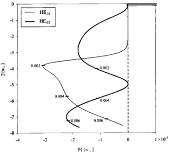
(36) and Eq. (37). In Fig. 7 we show␣ (in decibels per meter) as a function of the fiber’s normalized chirality pa-rameter g¯ for all semileaky modes in Fig. 4. The values found for this leakage loss can be severely high, so this new effect should not be disregarded in chiral optical fi-bers. Finally, in Fig. 8 we present, as an illustrative ex-ample, a root-locus plot for the complex solutions w⫹of two semi-leaky modes to bring out the conditions ex-pressed through inequalities (36).
5. CONCLUSIONS
A general theory of guided waves in optical fibers in which both core and cladding are chiral media has been derived. It was shown that, in chiral optical fibers, both surface and semileaky modes can propagate. This new leakage effect in chiral optical fibers, which is associated with semileaky modes, was physically discussed, and several
numerical results were presented for both surface and semileaky waves. Although only the case in which both core and cladding are chiral media was physically and nu-merically considered in this paper, one should note that semileaky modes also occur when only the cladding is chi-ral (i.e., the core may be a common isotropic medium with 1⫽ 0 as long as2⫽ 0). The continuous spectrum of radiation modes for chiral optical fibers was not analyzed in this paper.
The key feature that makes leakage possible is the ex-istence of two coupled characteristic waves in the clad-ding: Whenever only one of the core’s characteristic waves undergoes total internal reflection, a semileaky mode is generated. Hence other kinds of optical fiber with birefringent media, such as anisotropic optical fi-bers, should also exhibit this behavior.
A complex longitudinal wave number has to be consid-ered for every semileaky mode: The real part accounts for guidance (to account for the partial internal reflection at the core–cladding interface) and the imaginary part ac-counts for leakage (to account for the energy radiated through the core’s characteristic wave that is transmit-ted). Therefore complex solutions from properly specified Riemann sheets should be sought when one is solving the modal equation for an optical fiber with a chiral cladding. That is the reason why this leakage effect has been sys-tematically disregarded in the literature so far: Previous studies of chiral optical fibers were looking exclusively for surface waves, and hence only real roots were found when the corresponding modal equation was solved.
Common isotropic (or achiral) optical fibers are now well-known devices in optical science and technology. Nevertheless, new materials and effects are under cur-rent investigation. From the designer’s point of view, chiral optical fibers may increase flexibility in optimiza-tion procedures because of the extra chirality parameter. Still, further developments in artificially produced chiral materials—namely, for applications at optical frequencies—are needed.
F. M. Janeiro’s e-mail address is fernando.janeiro @lx.it.pt.
REFERENCES
1. A. Lakhtakia, ed., Selected Papers on Natural Optical Ac-tivity, Vol. MS15 of SPIE Milestone Series (SPIE Optical Engineering Press, Bellingham, Wash. 1990).
2. I. V. Lindell, A. H. Sihvola, and J. Kurkija¨rvi, ‘‘Karl F. Lindman—the last Hertzian and a harbinger of electromag-netic chirality,’’ IEEE Antennas Propag. Mag. 34, 24–30 (1992).
3. D. L. Jaggard, A. R. Mickelson, and C. H. Papas, ‘‘On elec-tromagnetic waves in chiral media,’’ J. Appl. Phys. 18, 211– 216 (1979).
4. S. A. Kuehl, S. S. Grove´, E. Kuehl, M. Bingle, and J. H. Clo-ete, ‘‘Manufacture of microwave chiral materials and their electromagnetic properties,’’ in Advances in Complex Elec-tromagnetic Materials, A. Priou, A. Sihvola, S. Tretyakov, and A. Vinogradov, eds. (Kluwer Academic, Dordrecht, The Netherlands, 1997), pp. 317–332.
5. H. Cory, ‘‘Chiral devices—an overview of canonical prob-lems,’’ J. Electromagn. Waves Appl. 9, 805–829 (1995). 6. I. V. Lindell, A. H. Sihvola, S. A. Tretyakov, and A. J.
Vii-tanen, Electromagnetic Waves in Chiral and Bi-Isotropic Media (Artech House, Boston, Mass., 1994), pp. 119–151.
Fig. 7. Leakage loss versus chirality for the semileaky modes in Fig. 4. Surface modes become semileaky modes when the fiber’s normalized chirality parameter is above a certain critical value that depends on each individual mode.
Fig. 8. Root loci of normalized variable w⫹for HE⫺31and HE⫺12 modes in terms of normalized parameter g¯ .
7. C. R. Paiva and A. M. Barbosa, ‘‘A method for the analysis of biisotropic planar waveguides—application to a grounded chiroslabguide,’’ Electromagnetics 11, 209–221 (1991).
8. H. Cory and I. Rosenhouse, ‘‘Electromagnetic wave propa-gation along a chiral slab,’’ IEE Proc. H 138, 51–54 (1991). 9. M. I. Oksanen, P. K. Koivisto, and I. V. Lindell, ‘‘Dispersion curves and fields for a chiral slab waveguide,’’ IEE Proc. H 138, 327–334 (1991).
10. N. Engheta and P. Pelet, ‘‘Surface waves in chiral layers,’’ Opt. Lett. 16, 723–725 (1991).
11. C. R. Paiva, A. L. Topa, and A. M. Barbosa, ‘‘Semileaky waves in dielectric chirowaveguides,’’ Opt. Lett. 17, 1670– 1672 (1992).
12. A. L. Topa, C. R. Paiva, and A. M. Barbosa, ‘‘Least squares boundary residual method for the analysis of step disconti-nuities in open chiral waveguides,’’ Int. J. Electron. Com-mun. 55, 281–291 (2001).
13. J. A. M. Svedin, ‘‘Propagation analysis of chirowaveguides using the finite-element method,’’ IEEE Trans. Microwave Theory Tech. 38, 1488–1496 (1990).
14. H. Cory and T. Tamir, ‘‘Coupling processes in circular open chirowaveguides,’’ IEE Proc. H 139, 165–170 (1992). 15. H. Cory and S. Gov, ‘‘Mode energy transfer along a circular
open chirowaveguide,’’ Microwave Opt. Technol. Lett. 6, 536–541 (1993).
16. A. K. Singh, Kh. S. Singh, P. Khastgir, S. P. Ojha, and O. N. Singh, ‘‘Modal cutoff condition of an optical chiral fiber with different chiralities in the core and the cladding,’’ J. Opt. Soc. Am. B 11, 1283–1287 (1994).
17. R. C. Qiu and I-T. Lu, ‘‘Guided waves in chiral optical fi-bers,’’ J. Opt. Soc. Am. A 11, 3212–3219 (1994).
18. S. F. Mahmoud, ‘‘Guided modes on open chirowaveguides,’’ IEEE Trans. Microwave Theory Tech. 43, 205–209 (1995). 19. F. M. Janeiro, A. L. Topa, and C. R. Paiva, ‘‘Semi-leaky
modes in chiral optical fibers,’’ presented at LEOS 2001, 14th Annual Meeting, San Diego, Calif., 2001.
20. S. T. Peng and A. A. Oliner, ‘‘Guidance and leakage proper-ties of a class of open dielectric waveguides. I. Math-ematical formulations,’’ IEEE Trans. Microwave Theory Tech. MTT-29, 843–855 (1981).
21. A. A. Oliner, S. T. Peng, T. I. Hsu, and A. Sanchez, ‘‘Guid-ance and leakage properties of a class of open dielectric waveguides. II. New physical effects,’’ IEEE Trans. Mi-crowave Theory Tech. MTT-29, 855–869 (1981).
22. K. Yamanouchi, T. Kamiya, and K. Shibayama, ‘‘New leaky surface waves in anisotropic metal-diffused optical waveguides,’’ IEEE Trans. Microwave Theory Tech. MTT-26, 298–305 (1978).
23. S. K. Sheem, W. K. Burns, and A. F. Milton, ‘‘Leaky mode propagation in Ti-diffused LiNbO3 and LiTaO3 waveguides,’’ Opt. Lett. 3, 76–78 (1978).
24. J. Cˇ tyroky´ and M. Cˇada, ‘‘Guidance and semileaky modes in anisotropic optical waveguides of LiNbO3type,’’ Opt. Com-mun. 27, 353–357 (1978).
25. D. Marcuse and I. P. Kaminov, ‘‘Modes of a symmetric slab optical waveguide in birefringent media. II. Slab with a coplanar optical axis,’’ IEEE J. Quantum Electron. QE-15, 92–101 (1979).
26. W. K. Burns, S. K. Sheem, and A. F. Milton, ‘‘Approximate calculation of leaky-mode loss coefficients for Ti-diffused LiNbO3waveguides,’’ IEEE J. Quantum Electron. QE-15, 1282–1289 (1979).
27. J. Cˇ tyroky´ and M. Cˇada, ‘‘Generalized WKB method for the analysis of light propagation in inhomogeneous anisotropic optical waveguides,’’ IEEE J. Quantum Electron. QE-17, 1064–1070 (1981).
28. M. Koshiba, H. Kumagami, and M. Suzuki, ‘‘Finite-element
solution of planar arbitrary anisotropic diffused optical waveguides,’’ J. Lightwave Technol. LT-3, 773–778 (1985). 29. A. Knoesen, T. K. Gaylord, and M. G. Moharam, ‘‘Hybrid
guided modes in uniaxial dielectric planar waveguides,’’ J. Lightwave Technol. 6, 1083–1104 (1988).
30. L. Torner, F. Canal, and J. H. Marco, ‘‘Leaky modes in multilayer uniaxial optical waveguides,’’ Appl. Opt. 29, 2805–2814 (1990).
31. L. Torner, J. Recolons, and J. P. Torres, ‘‘Guided-to-leaky mode transition in uniaxial optical slab waveguides,’’ J. Lightwave Technol. 11, 1592–1600 (1993).
32. R. E. Smith and S. N. Houde-Walter, ‘‘The migration of bound and leaky solutions to the waveguide dispersion re-lation,’’ J. Lightwave Technol. 11, 1760–1768 (1993). 33. A. D’Orazio, M. De Sario, V. Petruzzelli, and F. Prudenzano,
‘‘Leaky wave propagation in planar multilayer birefringent waveguides: longitudinal dielectric tensor configurations,’’ J. Lightwave Technol. 12, 453–462 (1994).
34. T. A. Maldonado and T. K. Gaylord, ‘‘Hybrid guided modes in biaxial planar waveguides,’’ J. Lightwave Technol. 14, 486–499 (1996).
35. R. E. Collin, Field Theory of Guided Waves, 2nd ed., (IEEE Press, New York, 1991), pp. 725–744.
36. E. U. Condon, ‘‘Theory of optical rotatory power,’’ Rev. Mod. Phys. 9, 432–457 (1937).
37. A. H. Sihvola and I. V. Lindell, ‘‘Bi-isotropic constitutive re-lations,’’ Microwave Opt. Technol. Lett. 4, 295–297 (1991). 38. A. Lakhtakia, Beltrami Fields in Chiral Media (World
Sci-entific, Singapore, 1994).
39. A. Lakhtakia and W. S. Weiglhofer, ‘‘Are linear, nonrecipro-cal, biisotropic media forbidden?’’ IEEE Trans. Microwave Theory Tech. 42, 1715–1716 (1994).
40. A. Lakhtakia and W. S. Weiglhofer, ‘‘Constraint on linear, homogeneous constitutive relations,’’ Phys. Rev. E 50, 5017–5019 (1994).
41. W. S. Weiglhofer and A. Lakhtakia, ‘‘A brief review of a new development for constitutive relations for linear bi-anisotropic media,’’ IEEE Antennas Propag. Mag. 37, 32–35 (1995).
42. W. S. Weiglhofer and A. Lakhtakia, ‘‘The Post constraint re-visited,’’ Int. J. Electron. Commun. 52, 276–279 (1998). 43. E. J. Post, Formal Structure of Electromagnetics—General
Covariance and Electromagnetics (Dover, Mineola, N.Y., 1997), pp. 129, 168–171.
44. A. H. Sihvola, ‘‘Are nonreciprocal bi-isotropic media forbid-den indeed?’’ IEEE Trans. Microwave Theory Tech. 43, 2160–2162 (1995).
45. S. Tretyakov, ‘‘Anything wrong with the naturally non-reciprocal materials?’’ IEEE Antennas Propag. Mag. 38, 84–85 (1996).
46. J. C. Monzon, ‘‘Author’s reply,’’ IEEE Trans. Antennas Propag. 45, 749 (1997).
47. I. V. Lindell, A. H. Sihvola, S. A. Tretyakov, and A. J. Vii-tanen, Electromagnetic Waves in Chiral and Bi-Isotropic Media (Artech House, Boston, Mass., 1994), pp. 23–58. 48. A. Lakhtakia, ‘‘Recent contributions to classical
electromag-netic theory of chiral media: what next?’’ Speculations Sci. Technol. 14, 2–17 (1991).
49. M. J. Adams, An Introduction to Optical Waveguides (Wiley, Chichester, UK, 1981), pp. 223–228.
50. A. W. Snyder and J. D. Love, Optical Waveguide Theory (Chapman & Hall, London, 1983), pp. 248–259.
51. M. Abramowitz and I. A. Stegun, eds., Handbook of Math-ematical Functions (Dover, New York, 1965), Eq. (9.7.2). 52. M. P. Carpentier and A. F. dos Santos, ‘‘Solution of
equa-tions involving analytic funcequa-tions,’’ J. Comput. Phys. 45, 210–220 (1982).