Abstract—This paper presents an antenna loaded with
metamaterial to enhance its gain and directivity to improve the performance of a ground-penetrating radar system (GPR). We adjusted the parameters of the antenna to change its equivalent capacitance and inductance and applied an operating frequency of 0.5 GHz-1.2 GHz to create an ultra-wideband antenna. On the basis of this operating frequency, we also designed the corresponding negative permittivity and permeability materials to simulate a patch antenna and material in a 1 GHz frequency band. The high gain and directivity of the antenna loaded with single-negative material were verified by simulation. Compared to the original antenna, the maximum gain increased by 7 dB and its directivity was greatly improved.
Index Terms— Metamaterial-based antenna, negative permittivity, negative
permeability, gain enhancement.
I. INTRODUCTION
Metamaterials are a type of new artificial electromagnetic material. These include left-handed
materials [1-2], zero-refraction materials [3-5], single-negative materials, right/left-hand transmission
lines, and photonic crystals, among others. These artificial materials are not present in nature.
Metamaterials have been widely used in various fields such as various special antenna designs [6-10],
optical imaging [11], electromagnetic wave stealth, subwavelength waveguide devices [12], leaky
wave elements [13], and many others. The metamaterials loading on the antenna can result in antenna
miniaturization, wide passband, high gain, and other functions. The current small antennas based on
metamaterials have been extensively studied. Resonant antennas based on a composite
right/left-handed (CRLH) or decentralized design include negative- and zero-order resonant antennas
Li Liu1,Chengguang Zhang1, Yu Liu2,Yujin Hua2
1
Key Laboratory of Exploration Technologies for Oil and Gas Resources, Ministry of Education, Yangtze University, Wuhan, China
Li Liu ([email protected]); Chengguang Zhang ([email protected]) 2
School of Geodesy and Geomatics, Wuhan University, Wuhan, China
[14]. Micro-antennas based on metamaterial loading include negative permeability metamaterials [15],
high-permeability shells [16], magnetic photonic crystals (MPC) [17], and Ziolkowski’s proposed
near-field resonant parasitic antennas [18-19]. Meta-resonator antennas [20-21] include those based
on split-ring resonators (SRRs) and complementary split-ring resonator antennas (CSRRs). Loaded
hyper-surface antennas [22-23] include electromagnetic band gap structured (EBG) and reactive
impedance surface (RIS) antennas. These promote the miniaturization of the antenna size, reduce the
surface wave interference, and improve the radiation characteristics.
Bow tie antennas have many advantages, including light weight, easy design and fabrication, better
symmetry in radiation, planar structure, and compact size among other factors. These solve the
problem of antenna practicality of the traditional ground-penetrating radar (GPR), which is low
because of its excessive size, expensive cost, and insufficient bandwidth. But issues remain, as the
antenna gain is not high and the directionality is inaccurate and affects the GPR performance. This
paper assesses the application of electromagnetic metamaterials in the new GPR antennas. These
ultra-wideband antennas have an operating frequency of 0.5 GHz-1.2 GHz. Single-negative material
with an operating frequency of approximately 1 GHz is loaded into the antennas to improve their
directivity and gain.
II. ANTENNA DESIGN AND METAMATERIALS
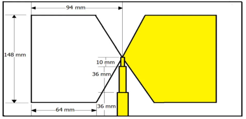
The design of the double bow tie antenna is shown in Fig. 1. The FR-4 substrate
(
r
4, tan
0.025
) has a length of 220 mm, a width of 168 mm, and a thickness of 1.6 mm. Wedesigned the antenna's radiation plate and feeder on both sides of the substrate. The radiation film and
feeder are both 0.03 mm thick copper. As shown in Figure 1, the size of the radiation film is 148 mm
x 64 mm x 94 mm. The feeder is symmetrical with a three-section impedance transformer. The first
section of the impedance transformer has a length of 10 mm and a width of 2.6 mm, the second
section has a length of 36 mm and a width of 3.5 mm, and the third section has a length of 36 mm and
Fig. 1. The structure of a double bow tie antenna.
Fig. 2 shows the antenna simulation. When the S11 parameter <-9 dB for the passband, the relative
bandwidth can reach more than 90%, while the general antenna broadband is only up to 10%. Due to the
structure of antenna, because there is no reflector on the back of the radiator plate, the radiation plate
capacitance is small. This is conducive to electromagnetic radiation moving outward to avoid the energy that
is bounded in the antenna. However, this will also increase the input impedance of the radiation plate, and we
found that the angle of the radiation plate is large. According to the equation (1) of the characteristic
impedance of a bow tie antenna, a greater flare angle (
) can indirectly reduce the capacitance, therebyincreasing the input impedance. In addition, the thickness of the substrate is set at 1.6 mm compared to the
usual 2.5 mm substrate, so the equivalent capacitance increases. Since the feeding microstrip line is
symmetrical, its characteristic impedance will be lower than that of the single-sided microstrip feeder. The
input impedance of the antenna is matched as close as possible to 50 Ω by an impedance transformer. The
mutual compensation between the equivalent capacitors causes the S11 parameter of the antenna to be
relatively gentle. In addition, the extension of the bow tie antenna improves the antenna’s radiation
performance.
120 ln[cot( )] 4
zin
(1)In a particular frequency, if the permittivity is negative and the permeability is positive, the material is
called negative permittivity material. According to an analysis of the constitutive relations, we know that the
electromagnetic waves at this time cannot pass through the material. Based on an analysis of the short metal,
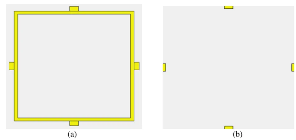
the structural design of the negative permittivity material is shown in Fig. 3. The FR-4 substrate
(
r
4, tan
0.025
) has a length of 80 mm, a width of 80 mm, and a thickness of 2.5 mm. The yellowsurface is pure copper with a thickness of 0.03 mm and a ring spacing of 2 mm. The back yellow part is 5 mm
in length and 3 mm in width. For the electromagnetic wave vertical incident material, due to the symmetry of
the structure, there is no requirement for the direction of the incident electric field. Fig. 4 shows the
S-parameter curve of the single-negative material.
(a) (b)
Fig. 3. (a) (b) show the front and back structure of the materials.
Fig. 4. S-parameter curve of the single-negative material.
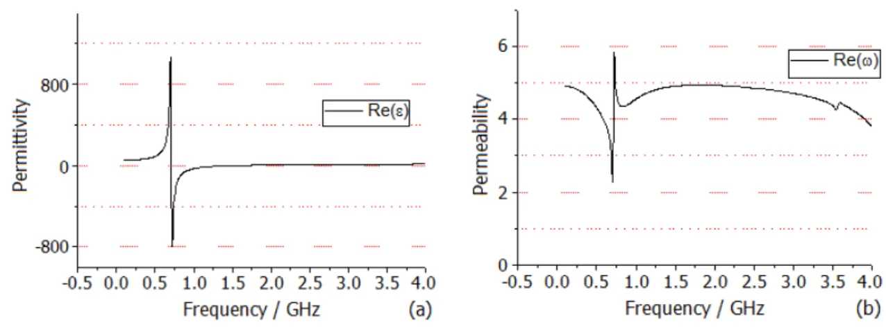
Fig. 4 presents the material of the approximately 0.75 GHz stop band. The inversion of its constitutive
parameters shows that the permittivity is negative and the permeability is positive in this frequency, which
of the material changing with the frequency.
Fig. 5. (a) (b) Permittivity and permeability of the material changing with the frequency.
Material with positive permittivity and negative permeability is called negative permeability material, and
we used the electromagnetic vertical incident material. In Fig. 6, the FR-4 substrate (
r
4, tan
0.025
)has a length of 40 mm, a width of 80 mm, and a thickness of 3 mm. The yellow part is metallic copper
symmetrical with the substrate, with a length of 20 mm and a width of 75 mm. When magnetic resonance
occurs, the metal sheet of the substrate on the front and back also acts as an SRR. This material can also
engender electrical resonance concomitantly. Fig. 7 shows the equivalent LC circuit of the material when
magnetic resonance and electrical resonance occur.
Fig. 7. (a) (b) The equivalent circuit diagram when magnetic resonance and electrical resonance occur
In Fig. 7 (a), Cm, Lm, and Ce are the capacitance between the copper pieces, the inductance of the metal
copper sheet, and the capacitance between the adjacent copper pieces, respectively. Cm and Ce are the same
in Fig. 7 (b) as in Fig. 7 (a), except that the inductance of the metal sheet changes and the calculation is
equivalent to the inductance calculation of the double conductor. Fig. 8 shows the S-parameter curves of
single-negative material.
Fig. 8. S-parameter curves of single-negative material.
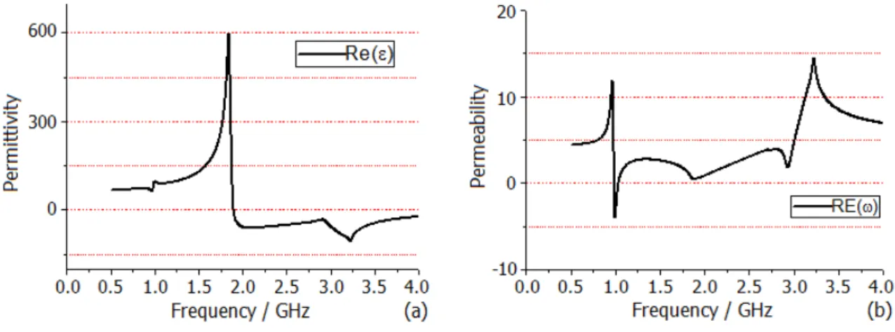
Through the inversion of the above diagram, we found a frequency of 1 GHz and 3 GHz around the
occurrence of magnetic resonance. To verify these results, we observed the surface current at three frequency
(a) (b) (c) Fig. 9. Surface flow diagram at (a) 1 GHz, (b) 3 GHz, and (C) 4 GHz.
Fig. 9 (a) shows the surface current distribution at 1 GHz. The current direction of the two pieces of metal
plate in the front and back in the opposite direction is equivalent to a magnetic dipole, which verifies that the
magnetic resonance occurs at 1 GHz. Fig. 9 (b) shows the surface current distribution at 3 GHz. The metal
plate in the front and back on the opposite current flow, and then the current flows to form a clear three
circulation. This shows that the magnetic resonance at this time is much stronger than at 1 GHz, and the
S-parameter values are consistent. Fig. 9 (c) features the metal sheet current direction at 4 GHz. The direction
of the current on both sides of the figure is in the same direction, which is precisely the performance of
electrical resonance. By comparing the above with the equivalent circuit diagram, we can see that the
simulated current direction is consistent with the red current direction in the equivalent circuit, which is
further proof of the above. Fig. 10 shows the permittivity and permeability of the material changing with the
frequency.
Fig. 10. (a) (b) Permittivity and permeability of the material changing with the frequency.
magnetic resonance is generated at 3 GHz in the surface current diagram, the permeability is not less than zero
at 3 GHz, which is mainly due to the magnetic dipole formed by the surface current.
III. SIMULATION AND ANALYSIS OF THE METAMATERIAL-LOADED BOW-TIE
The upper part of Fig. 11 is the discrete feed antenna and the bottom orange part is the material. The
distance between the material and the antenna is H, H = 50 mm. Due to the symmetry of the negative
permittivity material, there is no requirement for the polarization direction of the radiation field of the antenna
in the space during the loading process.
Fig. 11. Antenna structure with loading materials.
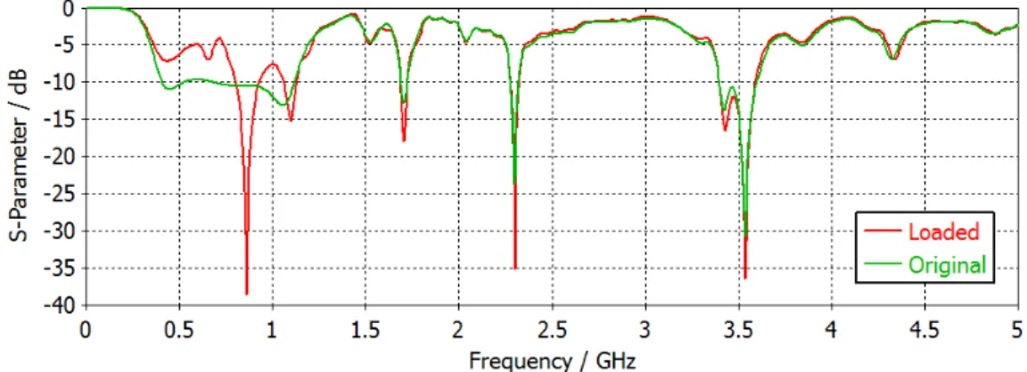
The result of comparing the antenna loaded the negative permittivity material and the original antenna is
shown in Fig. 12 and Fig. 13.
Fig. 13. (a) (b) The far field direction of antenna (a) with loading negative permittivity material and (b) without loading at 0.86 GHz.
In Fig. 12, the red curve is an antenna simulation that loads metamaterial and the green curve is an
antenna simulation that does not load metamaterial. We can see the effect of the negative permittivity
of the metamaterial on the antenna. It limits the passband of the antenna’s S11 parameter.
Electromagnetic waves propagating to the antenna are reflected back in its negative permittivity
frequency range. This is equivalent to the realization of the two radiations, thereby enhancing the gain
and directionality of the main radiation direction and inhibiting the antenna's backward radiation. Fig.
13 shows that the gain of the original antenna has been improved. With the highest gain at 0° in Fig.
13 (a), the main direction of propagation has also shifted from the original backward direction to the
forward direction.
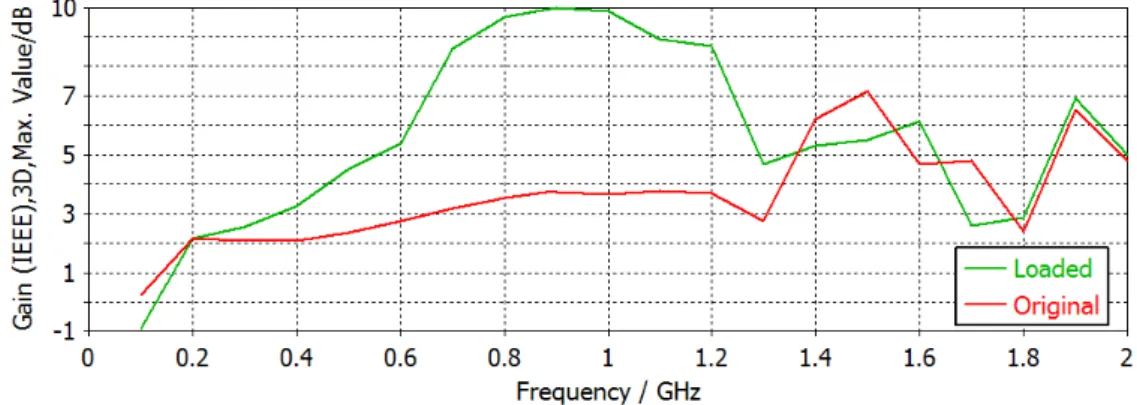
Fig. 14. Gain simulation results of the antenna with loading negative permittivity material and without loading.
Fig. 14 shows the gain for the antenna in two different situations, the green gain for the loaded
metamaterial and the red gain for the non-loaded metamaterial. We calculated the antenna gain using
frequency range. From the diagram analysis, we can see that the antenna gain without negative
permittivity was very gentle, approximately 3 dB in the frequency range of 0.2 GHz-1.3 GHz.
However, the antenna gain with the negative permittivity material was greatly improved, with a
maximum increase of 7 dB in the same frequency range. Therefore, we concluded that the loading of
the negative permittivity material enabled the antenna to achieve high gain and high directivity.
(a) (b)
Fig. 15. (a) Electric field direction 50 mm from the antenna, (b) the back of the antenna structure with loading material
The negative permeability material we use is the structure of in Fig. 5 (b). Unlike loading negative
permittivity materials, we need to know the polarization direction of the radiated electric field of the
antenna so the electromagnetic field can generate resonance with the material. Fig. 15 (a) shows the
electric field direction 50 mm from the antenna; (b) shows the back of the antenna with negative
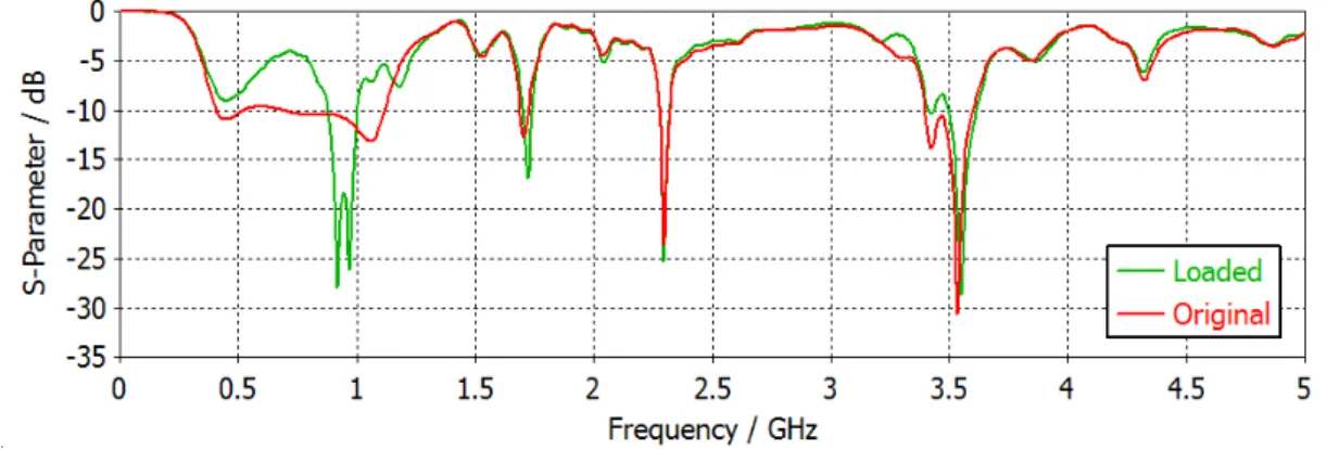
permeability material added. The result of comparing the antenna with loaded the negative
permeability material and the original antenna is shown in Fig. 16 and Fig. 17.
Figure 17. The far field direction of the antenna (a) with loading negative permeability material and (b) without loading at 1 GHz
In Fig. 16, the green curve is an antenna simulation that loads metamaterial and the red curve is an
antenna simulation that does not load metamaterial. We can see the effect of the negative permeability
of the metamaterial on the antenna. It also limits the passband of the antenna’s S11 parameter.
Electromagnetic waves propagating to the antenna are reflected back in its negative permeability
frequency range. This is equivalent to the realization of the two radiations, thereby enhancing the gain
and directionality of the main radiation direction and inhibiting the antenna's backward radiation. Fig.
17 shows that the gain of the original antenna has improved. With the highest gain at 0° in Fig. 17 (a),
the main direction of propagation has also shifted from the original backward direction to the forward
direction.
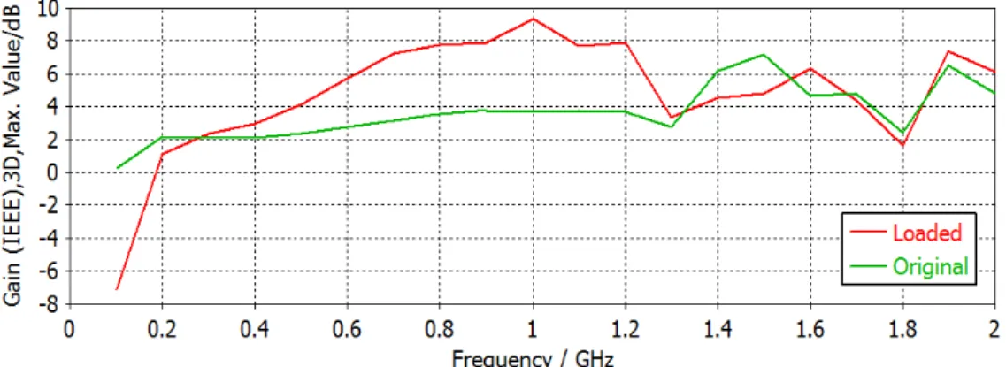
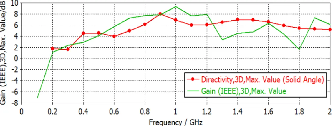
Fig. 18. Gain simulation results of the antenna with loading negative permeability material and without loading
Fig. 18 shows the gain for the antenna in two situations, the red gain for the loaded metamaterial
Microwave Studio, and every 0.1 GHz took a calculation point in the 0.1 GHz to 2 GHz frequency
range. From the diagram analysis, we can see that the antenna gain without negative permeability is
very gentle, approximately 3 dB in the frequency range of 0.2 GHz-1.3 GHz. However, the antenna
gain with the negative permittivity material was greatly improved, with a maximum increase of 6 dB
in the same frequency range. Therefore, we concluded that the loading of the negative permeability
material enabled the antenna to achieve high gain and directivity.
Fig. 19. The maximum gain comparison
We compared the antenna of this article with the antenna proposed by Rashmiranjan Nayak et
al[24]. Fig. 19 shows the maximum gain of the two antennas (the red line indicates the gain of
antenna designed by Rashmiranjan Nayak, and the green line is the antenna gain in this article). It can
be seen that in the operating frequency range from 0.5 GHz to 1.2 GHz, our antenna gain has
increased about 2 dB, while the size of the antenna designed by Rashmiranjan Nayak is about twice as
large as our antenna.
IV. CONCLUSION
In summary, the paper presented a high gain and directivity bow tie antenna of a GPR system with
metamaterial. An ultra-wideband antenna with an operating frequency of 0.5 GHz-1.2 GHz was
designed using CST Microwave Studio; the negative permittivity and permeability material had a
working frequency of approximately 1 GHz, realizing the design and simulation of a patch antenna
and material in the 1 GHz frequency band. Through the S-parameter inversion of the design material
and the analysis of the surface current at the corresponding frequency, we verified the material’s
antenna loaded with the single-negative material were verified via simulation. Compared to the
original antenna, the maximum gain increased by 7 dB and its directivity was greatly improved.
Consequently, it is effective and feasible to load a single-negative metamaterial onto an antenna for
high gain and directivity.
ACKNOWLEDGMENT
This work was supported by the National Natural Science Foundation of China (grant number
41774116).
REFERENCES
[1] Xiong, H., Hong, J.S., Jin, D.L. and Z. M. Zhang, A Novel Structure for Broadband Left-handed Metamaterial, Chin. Phys. B, 21, pp. 4101-4105, 2012.
[2] Kafesaki, M., Tsiapa, I., Katsarakis, N. & Koschny, Th., Left-handed Metamaterials: the Fishnet Structure and Its Variations, Physical Review B, 75, pp. 5114-5122, 2007.
[3] Sun, L. & Yu, K.W., Strategy for Designing Broadband Epsilon-near-zero Metamaterial with Loss Compensation by Gain Media, Applied Physics Letters, 100, pp. 1903-1906, 2012.
[4] Soemphol, C., Sonsilphong, A. & Wongkasem, N., Metamaterials with Near-zero Refractive Index Produced Using Fishnet Structures, Journal of Optics, 16, pp. 5104-5109, 2014.
[5] Sun, L., Gao, J. & Yang, X.D., Broadband Epsilon-near-zero Metamaterials with Step-like Metal-dielectric Multilayer Structures, Physical Review B, 87, pp. 5134-5139, 2013.
[6] Nilavalan, R., Hilton, G.S. & Benjamin, R., Wideband Printed Bowtie Antenna Element Development for Post Reception Synthetic Focusing Surface Penetrating Radar, Electronics Letters, 35, pp. 1771-1772, 1999.
[7] Soh, P.J., Mercuri, M., Pandey, G. & Vandenbosch, G.A.E., Dual-Band Planar Bowtie Monopole for a Fall-Detection Radar and Telemetry System, IEEE Antennas and Wireless Propagation Letters, 11, pp. 1698-1701, 2012.
[8] Byers, K.J., Harish, A.R., Seguin, S.A. & Leuschen, C.J., A Modified Wideband Dipole Antenna for an Airborne VHF Ice-Penetrating Radar, IEEE Antennas and Wireless Propagation Letters, 61, pp. 1435-1443, 2012.
[9] Mahmoud, A.M., Hoorfar, A. & Thajudeen, C., Enhanced Design of Bowtie Antennas over High-Impedance Surfaces: An Evolutionary Approach, IEEE Antenna and Propagation Society Meeting, Jul. pp. 270-271, 2013.
[10]Ranasinghe, H.M.P.B., Senanayake, S.M.P., Senarathne, U.I.P., & Gunawardena, A.U.A.W., Design of a Low Cost Cavity Backed Wideband Bow-tie Antenna for Ground Penetrating Radar Systems, IEEE 8th International Conference on Industrial and Information Systems, Dce. pp. 370-372, 2013.
[11]Pentry, J.B., Negative Refraction Makes a Perfect Lens, Physical Review Letters, 85, pp. 3966-3969, 2000. [12]Ozlem, O. & Mustafa, K., Utilization of Anisotropic Metamaterial Layers in Waveguide Miniaturization and
Transitions, IEEE Microwave and Wireless Components Letters, 17, pp. 754-756, 2007.
[13]Dong, Y.D. & Itoh, T., Composite Right/left-handed Substrate Integrated Waveguide Leaky-wave Structures, IEEE Transactions on Antennas and Propagation, 59, pp. 767-775, 2011.
[14]Paulotto, S., Baccarelli, P., Frezza, F. & Jackson, D.R., Full-wave modal dispersion analysis and broadside optimization for a class of microstrip CRLH leaky-wave antennas, Microwave Theory and Techniques, IEEE Transactions on, 56,pp. 2826-2837, 2008.
[15]Stuart, H.R. & Pidwerbetsky, A., Electrically small antenna elements using negative permittivity resonators. Antennas and Propagation, IEEE Transactions on, 54, pp. 1644-1653, 2006.
[16]Stuart, H. R. & Yaghjian, A.D., Approaching the Lower Bounds on Q for Electrically Small Electric-dipole Antennas Using High Permeability Shells, Antennas and Propagation, IEEE Transactions on, 58, pp. 3865-3872, 2010. [17]Mumcu, G., Sertel, K. & Volakis, J.L., Miniature Antenna Using Printed Coupled Lines Emulating Degenerate Band
Edge Crystals, Antennas and Propagation, IEEE Transactions on, 57, pp. 1618-1624, 2009.
[18]Ziolkowski, R.W., Jin, P., Nielsen, J. & Tanielian, M., Experimental Verification of Z Antennas at UHF Frequencies, Antennas and Wireless Propagation Letters, 8, pp. 1329-1333, 2009.
[19]Jin, P. & Ziolkowski, R.W., Low-Q, Electrically small, Efficient Near-field Resonant Parasitic Antennas, Antennas and Propagation, IEEE Transactions on, 57, pp. 2548-2563, 2009.
[20]Dong, Y., Toyao, H. & Itoh, T., Design and characterization of miniaturized patch antennas loaded with complementary split-ring resonators, Antennas and Propagation, IEEE Transactions on, 60, pp. 772-785, 2012.
[21]Kim, I. k., & Varadan, V. V., Electrically Small, Millimeter Wave Dual Band Meta-resonator Antennas, Antennas and Propagation, IEEE Transactions on, 58, pp. 3458-3463, 2010.
[23]Zhu, S. & Langley, R., Dual-band wearable textile antenna on an EBG substrate. Antennas and Propagation, IEEE Transactions on, 57, pp. 926-935, 2009.