Abstract— In this paper, we present a compact and low-profile
monopole antenna with a simple structure for the 2.6-2.73 GHz frequency band, the Worldwide Interoperability for Microwave Access (WiMAX) and the Wireless Local Area Network (WLAN) applications. The first configuration of our antenna mainly consists by three radiating elements: inverted L-shaped Stub1, L-shaped Stub2 and a rectangle Stub3. By adjusting the lengths of the three Stubs, three resonant frequencies can be achieved and adjusted separately. Then, the assembled between Stub2 and Stub3 gives the final design of our proposed antenna with a small overall size of 20 mm × 37 mm × 1.56 mm. From the experimental results it is observed that, the antenna prototype has achieved two operating bandwidths (S11≤ -10 dB): the first band from 2.62 to 2.73 GHz (110
MHz) and a second broadband from 3.02 to 7.30 GHz (4280 MHz) which combines WiMAX and WLAN applications. The antenna also exhibits an almost omnidirectional radiation patterns over the operating bands. The parameters which affect the performance of the antenna in terms of its frequency domain characteristics are studied in this paper. The details of the monopole antenna design along with simulated and experimental results are presented and discussed.
Index Terms—CPW-feed, Dual-band antenna, Monopole antenna, Multiband antenna, WiMAX/WLAN applications.
I. INTRODUCTION
In modern wireless communication systems, multiband antenna has been playing a very important
role for wireless service requirements. Wireless Local Area Network (WLAN) and Worldwide
Interoperability for Microwave Access (WiMAX) have been widely applied to mobile devices such as
handheld computers and smart phones, more and more engineers and researchers have focused their
interests on how to design multiband antennas that can be integrated in a portable wireless
communication device for several communication standards. In order to satisfy the IEEE 802.11
A Compact Dual-Band CPW-Fed Planar
Monopole Antenna for 2.62-2.73 GHz
Frequency Band, WiMAX and WLAN
Applications
Ahmed Zakaria Manouare1, Saida Ibnyaich2, Abdelaziz EL Idrissi1, Abdelilah Ghammaz1
1Department of Applied Physics, Laboratory of Electrical Systems and Telecommunications, Faculty of Sciences
and Technologies, Cadi Ayyad University, Marrakesh, Morocco.
2
Department of Physics, Laboratory of Electronics and Instrumentation, Faculty of Sciences Semlalia, Cadi Ayyad University, Marrakesh, Morocco.
Naima Amar Touhami3
3Laboratory of Information Systems and Telecommunications, Faculty of Sciences, Abdelmalek Essaadi
WLAN standards in the 5.2 GHz (5150–5350 MHz)/5.8 GHz (5725–5825 MHz) operating bands and
WiMAX 2.6/3.5/5.5 GHz (2500–2690/3400–3690/5250–5850 MHz) bands, multi-band antennas with
low cost, compact size, easy fabrication and higher performance are required. Several dual-band
antennas for WLAN applications were presented [1-5]. To enhance the bandwidth, a dual wideband
monopole antenna was realized with a parasitic patch using electromagnetic coupling mechanism to
cover the whole WLAN bands and WiMAX bands. However, the overall size of the antenna is
somewhat large (48 × 58 mm2), occupying much of the device space [6]. A compact wideband
LI-shaped monopole antenna with enough bandwidth to cover the whole WLAN and WiMAX operating
bands was obtained in [7]. A compact dual-wideband antenna with assembled monopoles is proposed
in [8]. A coplanar waveguide (CPW)-fed printed monopole antenna with an n-shaped slot for
dual-band operation is presented in [9]. In [10], a dual-dual-band slotted patch antenna with defective ground
has been designed to cover WLAN and WiMAX applications. In reference [11], a CPW-fed compact
meandered patch antenna for dual-band operation is presented. In [12], a CPW-fed dual-frequency
monopole antenna has been reported. In [13], a square-slot antenna with symmetrical L-strips is
presented for WLAN and WiMAX applications, but the three resonant frequencies cannot be tuned
independently. Many promising UWB antennas have been discussed in the literature [14-18].
In this paper, we present a compact dual-band CPW-fed planar monopole antenna for 2.6-2.73 GHz
frequency band, WiMAX and WLAN applications. The first stage of our design is a simple antenna
with three Stubs (Stub1, Stub2 and Stub3) which provides three resonant frequencies at 2.603 GHz,
3.429 GHz and 4.584 GHz. These frequencies can be tuned individually according to the parameters
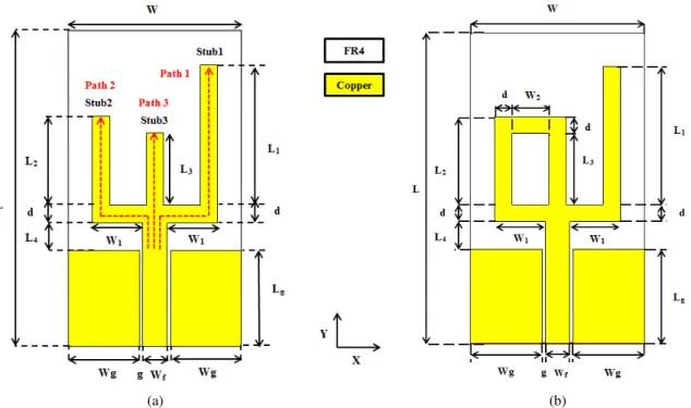
L1, L2 and L3, as shown in Fig. 1 (a). In the second stage, by assembling the Stub2 and the Stub3, as
shown in Fig. 1 (b), the proposed antenna satisfies a part of the 2.6 GHz band (first band) from 2.62 to
2.73 GHz and a second wide band from 3.02 to 7.30 GHz is formed to cover all the 5.2/5.8 GHz
WLAN operating bands and the 3.5/5.5 GHz WiMAX operating bands. Details of the antenna design
and the effects of the key structure parameters on the antenna performances are neatly examined and
discussed.
II. ANTENNA DESIGN
The geometries of the initial and proposed CPW-fed monopole antennas are shown in Fig. 1. Both
the antennas are designed on a 1.56 mm thick FR4 substrate having relative permittivity of 4.3, a loss
tangent of 0.025 and having overall dimensions of 20 (W) × 37 (L) mm2 and a coppering thickness of
the radiator t= 0.035 mm. The electromagnetic simulation software CST Microwave Studio based on
Finite Integration Technique (FIT) is used for the design. In both antennas, the CPW has a feed width
(a) (b)
Fig. 1. (a) Geometry of the initial antenna, (b) Geometry of the proposed antenna.
The radiating element is composed by three Stubs: inverted L-shaped Stub1 with L1= 16.5 mm,
L-shaped Stub2 with L2= 10.5 mm and a rectangle Stub3 with L3= 8.5 mm, as shown in Fig. 1 (a). By
adjusting the lengths (L1, L2 and L3) of these Stubs, three resonant frequencies can be generated and
adjusted independently. The optimized geometrical parameters describing the proposed antenna are
tabulated in Table I.
TABLE I.THE OPTIMIZED PROPOSED ANTENNA PARAMETERS
Parameters Values (mm)
W 20
L1 16.5
L3 8.5
W1 7.225
Lg 11.2
d 2
L 37
L2 10.5
L4 3.3
Wg 8.2
Wf 2.8
W2 5.625
Fig. 2 shows the different shapes in the evolution of the proposed antenna and the simulated result
of the reflection coefficient of the proposed antenna is presented in Fig. 3. The structure illustrated in
Shape 1 of Fig. 2 is the basic CPW-fed planar antenna which consists by an inverted L-shaped Stub1
acting as the monopole. When an additional L-shaped Stub2 is embedded to the monopole of Shape 1
obtained. Afterwards, a rectangle Stub3 is added to the Shape 2 (Shape 3) and the triple-band
structure is obtained: The first band from 2.519 to 2.673 GHz (154 MHz) centered at 2.603 GHz, the
second band from 3.058 to 4 GHz (942 MHz) centered at 3.429 GHz and the third band from 4.437 to
6.761 GHz (2324 MHz) centered at 4.584 GHz.
Finally, we can observe that the assembled between Stub2 and Stub3 (Proposed antenna) can
provide a wide band which cover all the WiMAX 3.5/5.5 GHz bands and the WLAN 5.2/5.8 GHz
bands. From the simulated reflection coefficient of this proposed monopole antenna, a resonance at
about 2.65 GHz is seen for the first band and two resonance frequencies 3.50 GHz and 5.956 GHz are
showed for the second broadband. Two operating bandwidths (S11≤ -10 dB) are achieved: The first
band from 2.519 to 2.729 GHz (210 MHz) and the second band from 3.093 to 6.684 GHz (3591
MHz).
Shape 1 Shape 2 Shape 3 Proposed Antenna Fig. 2. Evolution of the proposed CPW-fed monopole antenna.
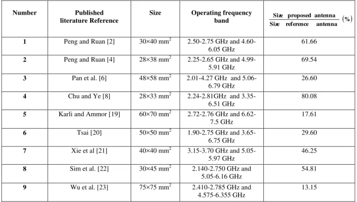
Table II shows a comprehensive comparison antenna size among our proposed antenna and other
compact multi-band antennas. As for our proposed antenna with an excellent dual-band characteristic
and a smaller size than those of the previously proposed dual-band antennas.
TABLE II.COMPARISONS OF ANTENNA SIZE AMONG PROPOSED ANTENNA AND OTHER COMPACT ANTENNAS
Number Published
literature Reference
Size Operating frequency
band SizeSizereferenceproposed antennaantenna %
1 Peng and Ruan [2] 30×40 mm2 2.50-2.75 GHz and 4.60-
6.05 GHz
61.66
2 Peng and Ruan [4] 28×38 mm2 2.25-2.65 GHz and
4.99-5.91 GHz
69.54
3 Pan et al. [6] 48×58 mm2 2.01-4.27 GHz and 5.06-
6.79 GHz
26.60
4 Chu and Ye [8] 28×33 mm2 2.24-2.81GHz and 3.35-
6.51 GHz
80.08
5 Karli and Ammor [19] 60×70 mm2 2.72-2.76 GHz and
6.62-7.5 GHz
17.61
6 Tsai [20] 50×50 mm2 1.90-2.75 GHz and 3.65-
6.75 GHz
29.60
7 Xie et al [21] 40×40 mm2 3.15-3.70 GHz and 5.05-
5.97 GHz
46.25
8 Sim et al. [22] 30×45 mm2 2.140-2.750 GHz and
5.05-6.16 GHz
54.81
9 Wu et al. [23] 75×75 mm2 2.410-2.785 GHz and
4.575-6.355 GHz
13.15
III. PARAMETRIC STUDY
The parametric study is important for a design because it provides some understanding of the
antenna characteristics to the antenna designer. Therefore, the effects of the design parameters for L1,
L2, L3, (L2 and L3), W1 and Lg on the initial antenna and the proposed monopole antenna
characteristics are investigated here. The study is based on the antennas structures shown in Fig. 1.
A. The inverted L-shaped Stub1 (L1)
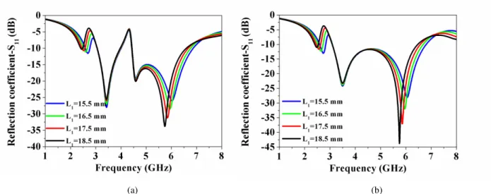
The effects of the length L1 of the initial antenna are plotted in Fig. 4(a). This figure shows the
simulated reflection coefficient when the length of L1 changes (L2= 10.5 mm and L3= 8.5 mm). By
adjusting the length of L1, the total length of Stub1 varies. It is seen that the increase in L1 decreases
the resonant frequency of the first band and vice versa. The resonant frequency of the third band is
also affected.
Fig. 4(b) shows the variation of the reflection coefficient of the proposed antenna when the length
(a) (b)
Fig. 4. Simulated reflection coefficients for different values of: (a) L1 of the initial antenna and (b) L1 of the proposed
antenna.
B. The L-shaped Stub2 (L2) of the initial antenna
Fig. 5(a) shows the simulation of the reflection coefficient with variation of L2 (L1= 16.5 mm and
L3= 8.5 mm) of the antenna presented in Fig. 1(a). By tuning the length of L2 from 9.5 mm to 12.5
mm, it is clear that the raise in L2 decreases the resonant frequency of the second band. The resonant
frequency of the first band is slightly affected.
C. The rectangle Stub3 (L3) of the initial antenna
Varying the length L3 of the initial antenna to be 7.5, 8.5, 9.5 and 10.5 mm, it can be seen from Fig.
5(b) and Table III that with the increasing of length L3, the third resonant frequency shifts towards the
lower frequency with an increase in the third band slightly, while the other resonant frequencies bands
have not been changed.
(a) (b)
TABLE III.THE VALUES OF BANDWIDTH OF THE THIRD BAND FOR DIFFERENT VALUES OF L3 OF THE INITIAL ANTENNA
D. The simultaneous variation of L2 and L3 of the proposed antenna
Fig. 6(a) shows the simulated reflection coefficient as a function of L2, the length of Stub2 and L3,
the length of Stub3 of the proposed monopole antenna presented in Fig. 1(b). Small effects on the
antenna’s first and third resonant frequencies and large effects on the second resonant frequency are
seen. The second band is shifted to lower frequencies with an increase in L2 and the parameter S11 of
the third resonant frequency is ameliorated when raising the length L3.
E. The width W1 of the proposed antenna
Fig. 6(b) shows the simulated reflection coefficient as a function of W1. It is seen from the plot that
the 5-GHz operating band is strongly affected by the variations in W1, and the resonant frequency is
shifted to lower frequencies when W1 is increased from 6.225 mm to 7.725 mm and the level of S11
-parameter is enhanced from -27.70 dB to -58.57 dB. Small effects on the antenna’s first and middle
bands are also seen from the plot.
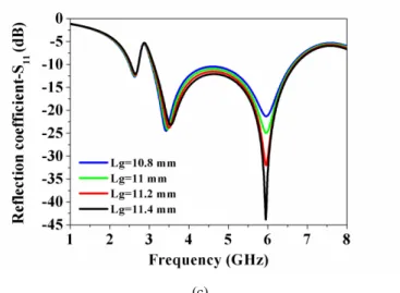
F. The effect of ground plane length Lg of the proposed antenna
The finite ground CPW feeding mechanism of the proposed antenna is the capability of impedance
matching at the operating frequencies. For this, the effect of the ground plane length Lg on the antenna
characteristics has been illustrated. The effect of ground plane length Lg on the impedance matching is
investigated and the reflection coefficient for the proposed antenna is shown in Fig. 6(c). It is
observed that higher value of Lg gives a good impedance matching in the 5-GHz band.
(a) (b)
Length L3 (mm) Third Band (GHz)
7.5 4.794-6.754 (1.940 GHz)
8.5 4.437-6.768 (2.331 GHz)
9.5 10.5
(c)
Fig. 6. Simulated reflection coefficients for different values of: (a) L2 and L3 of the proposed antenna (b) W1 of the proposed
antenna and (c) Lg of the proposed antenna.
IV. RESULTS AND DISCUSSION
A. Reflection coefficient results
The dual-band planar monopole antenna is simulated using the CST Microwave Studio V13. A
prototype structure of the proposed antenna has been constructed and experimentally studied. The
SMA female connector is used for feeding with characteristic impedance of 50 Ω, as shown in Fig. 7.
The reflection coefficient is measured with Rohde and Schwarz ZVB 20 vector network analyzer,
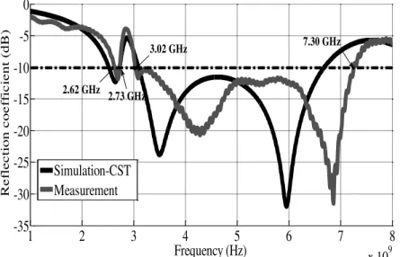
which its frequency range is, limited to 20 GHz. Fig. 8 shows the simulated and measured results of
the reflection coefficient of the proposed antenna. The measured impedance bandwidths for S11≤ -10
dB are about 110 MHz (2.62 to 2.73 GHz, ƒr1= 2.69 GHz) and 4280 MHz (3.02 to 7.30 GHz, ƒr2=
4.28 GHz and ƒr3= 6.86 GHz), which makes it easy to cover the required bandwidths for WiMAX
bands (3.40-3.69 GHz and 5.25-5.85 GHz), WLAN bands (5.15-5.35 GHz and 5.725-5.825 GHz) and
a part of 2.60 GHz band from 2.50 to 2.69 GHz. Seen from Fig. 8, the simulated −10 dB impedance
bandwidths for the first band is ranged from 2.519 to 2.729 GHz (210 MHz) and for the second band
is ranged from 3.093 to 6.684 GHz (3591 MHz). We note a good agreement between the simulated
and measured results with a good impedance matching in the operating bands. The small difference
between the measured and simulated results is due to the effect of SMA connector soldering and
fabrication tolerance.
1 2 3 4 5 6 7 8 x 10⁹ -35 -30 -25 -20 -15 -10 -5 0 Frequency (Hz) R e fl e c ti on c oe ff ic ie nt ( dB ) Simulation-CST Measurement 2.73 GHz 2.62 GHz
3.02 GHz 7.30 GHz
Fig. 8. The simulated and the measured reflection coefficient for the proposed antenna.
B. Current distributions of the initial antenna
From the simulated reflection coefficient characteristics of the initial antenna presented in Fig. 1(a),
resonances can be observed at ƒ1= 2.603 GHz, ƒ2= 3.429 GHz and ƒ3= 4.584 GHz. The probable
current paths for the first, the second and the third resonance frequencies are similar to resonant Path
1, resonant Path 2 and resonant Path 3, respectively, as shown in Fig. 1(a) (red line).
In order to better understand the initial antenna behavior, the current distributions of the three-band
antenna at frequencies of 2.603 GHz, 3.429 GHz and 4.584 GHz are simulated and shown
respectively in Figs. 9(a), (b) and (c). It can be evidently seen from Fig. 9 that the current distributions
at the three resonant frequencies are different. Concerning the first resonant mode (ƒ1= 2.603 GHz), a
large surface of the current density is observed along the inverted L-shaped Stub1. Whereas for the
second frequency band (ƒ2= 3.429 GHz), the current distributions is mainly distributed along the
L-shaped Stub2, on the other hand for the third resonant mode (ƒ3= 4.584 GHz), the current distributions
becomes more concentrated along the Stub3. Nevertheless, they also have a common characteristic
that is a large current is concentrated along the feed line.
(a) (b) (c)
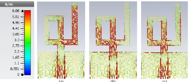
C. Current distributions of the proposed antenna
In order to further demonstrate the dual-band operation mechanism, the surface current distributions
on the whole proposed antenna at different resonant frequencies are shown in Figs 10(a)-(c). It can be
evidently seen that the current has different distributions along the optimized structure in different
bands. Fig. 10(a) shows that the current distributions are forced to flow around the inverted L-shaped
Stub1 and the rectangle Stub3. The variations on the length L1 affect the second resonant frequency of
the wide band. Figs 10(b) and 10(c) show the current distributions at frequencies 3.50 GHz and 4.60
GHz. The L-shaped Stub2 and the rectangle Stub3 contributed essentially to radiation at frequencies
of 3.50 GHz and 4.60 GHz, respectively. The resonant currents at frequencies of 3.50 GHz and 4.60
GHz are distributed on both the Stub2 (L2) and Stub3 (L3).
(a) (b) (c)
Fig. 10. Simulated current distribution of the proposed antenna at frequencies (a) 2.65 GHz, (b) 3.50 GHz and (c) 4.60 GHz.
D. Radiation patterns, gain and efficiency
The Simulated E-plane (YOZ) and H-plane (XOZ) radiation patterns at 2.65, 3.50, 5.20 and 5.80
GHz are normalized and shown in Fig. 11. It is observed that the proposed antenna has almost an
omni-directional radiation patterns in the H-plane and nearly bi-directional radiation patterns in the
E-plane over the desired operating bands.
(a) (b) (c) (d)
Fig. 12(a) and Fig. 12(b) show simulated peak gain and radiation efficiency across the operating
bands. The maximum simulated peak antenna gains and radiation efficiencies are 1.45/1.55/3.31dBi
and 81.1/77.5/75% at the first band and the second band, respectively.
(a) (b)
Fig. 12. Simulated peak gain and radiation efficiency across operating frequencies for proposed monopole antenna (a) first band, (b) second band.
V. CONCLUSION
A small monopole antenna for dual-band operations has been presented. The proposed monopole
antenna has a simple planar structure and is easy to be printed on FR4 substrate with small size of 20
× 37 mm2. The initial antenna consists by three Stubs: inverted L-shaped Stub1, L-shaped Stub2 and
rectangle Stub3. This configuration can generate three bands centered at about 2.603 GHz, 3.429 GHz
and 4.584 GHz. The three resonant frequencies can be tuned individually by adjusting the length of
the three Stubs. Thus, by combining between Stub2 and Stub3 (proposed antenna), two operating
bands can be obtained with a wide second band which covers all the WiMAX bands 3.5/5.5 GHz and
WLAN bands 5.2/5.8 GHz. Both the simulated and measured results show that the demonstrated
antenna can successfully achieved two operating bands. The measured -10 dB reflection coefficient
bandwidths cover 2.62-2.73 GHz (110 MHz) and 3.02-7.30 GHz (4280 MHz) bands, which satisfied
the frequency requirements of WiMAX, WLAN and a part of the 2.6 GHz band from 2.50 to 2.69
GHz. In addition, the proposed antenna provides good radiation patterns in the working bands, which
makes it suitable for integrating into portable devices. This CPW-fed planar monopole antenna is a
good candidate for wireless communication systems.
ACKNOWLEDGMENT
This work was supported by the National Center for Scientific and Technical Research (CNRST).
The authors would like to thank Professor Naima Amar Touhami from Faculty of Sciences of Tetouan
REFERENCES
[1] S. Jo, H. Choi, B. Shin, S. Oh, and J. Lee, “A CPW-Fed Rectangular Ring Monopole Antenna for WLAN
Applications,”International Journal of Antennas and Propagation, vol. 2014, Article ID 951968, 2014.
[2] L. Peng, and C.-Li Ruan, “A Microstrip Fed Patch Antenna with Two Parasitic Invert L Stubs for Dual-Band
WLAN Applications,”Wirel. Pers. Commun, vol. 57, no. 4, pp. 727-734, 2011.
[3] L. Zhang, Y.-C. Jiao, G. Zhao, Y. Song, and F.-S. Zhang, “Broadband Dual-Band CPW-Fed Closed Rectangular
Ring Monopole Antenna with a Vertical Strip for WLAN Operation,”Microwave and Optical Technology Letters,
vol. 50, no. 7, pp. 1929–1931, 2008.
[4] L. Peng, and C.-L. Ruan, “A Microstrip Fed Monopole Patch Antenna with three Stubs for Dual-band WLAN
Applications,”J. of Electromagn. Waves and Appl, vol. 21, no. 15, pp. 2359–2369, 2007.
[5] C.-Y. Huang, and E.-Z. Yu, “A Slot-Monopole Antenna for Dual-Band WLAN Applications,”IEEE Antennas
Wirel. Propag. Lett, vol. 10, pp. 500-502, 2011.
[6] C.-Y. Pan, T.-S. Horng, W.-S. Chen, and C.-H. Huang, “Dual Wideband Printed Monopole Antenna for
WLAN/WiMAX Applications,”IEEE Antennas Wirel. Propag. Lett, vol. 6, pp. 149-151, 2007.
[7] J. Il Kim, and Y. Jee, “Design of Ultra wideband Coplanar Waveguide-Fed LI-Shape Planar Monopole Antennas,”
IEEE Antennas Wirel. Propag. Lett, vol. 6, pp. 383-387, 2007.
[8] Q.-X. Chu, and L.-H. Ye, “Design of Compact Dual-Wideband Antenna with Assembled Monopoles,” IEEE
Trans. Antennas Propag, vol. 58, no. 12, pp. 4063-4066, Dec. 2010.
[9] S. T. Fan, Y. Z. Yin, W. Hu, K. Song, and B. Li, “ Novel CPW-Fed Printed Monopole Antenna with an n-Shaped
Slot for Dual-Band Operations,” Microwave and Optical Technology Letters, vol. 54, no. 1, pp. 240-242, 2012.
[10] C.-M. Wu, J.-W. Syu, and W.-C. Liu, “Dual-Band Slotted Patch Antenna with Defective Ground for
WLAN/WiMAX Applications, ”Progress In Electromagnetics Research Letters, vol. 53, pp. 1–6, 2015.
[11] W. C. Liu, and W. R. Chen, “CPW-fed compact meandered patch antenna for dual-band operation,”Electronics
Letters, vol. 40, no. 18, pp. 1094-1095, 2004.
[12] H.-D. Chen, and H.-T. Chen, “A CPW-Fed Dual-Frequency Monopole Antenna,”IEEE Trans. Antennas Propag,
vol. 52, no. 4, pp. 978-982, 2004.
[13] W. Hu, Y.-Z. Yin, P. Fei, and X. Yang, “Compact Triband Square-Slot Antenna with Symmetrical L-Strips for
WLAN/WiMAX Applications,”IEEE Antennas Wirel. Propag. Lett, vol. 10, pp. 462-465, 2011.
[14] A. Boutejdar, A. A. Ibrahim, and E. P. Burte, “A Compact Multiple Band-Notched Planer Antenna with Enhanced
Bandwidth Using Parasitic Strip Lumped Capacitors and DGS-Technique,”TELKOMNIKA Indonesian Journal of
Electrical Engineering, vol. 13, no. 2, pp. 203-208, 2015.
[15] A. Boutejdar, A. A. Ibrahim, and E. P. Burte, “Novel Microstrip Antenna Aims at UWB Applications,”
Microwaves & RF, vol. 7, no. 7, pp. 8-14, 2015.
[16] A. A. Ibrahim, M. A. Abdalla, and A. Boutejdar, “Resonator Switching Techniques for Notched UWB Antenna in
Wireless Applications,”IET Microwaves, Antennas & Propagation, vol. 9, no. 13, pp. 1468-1477, 2015.
[17] A.A. Ibrahim, M.A. Abdalla, and A. Boutejdar, “A Printed Compact Band Notched Antenna Using Octagonal
Radiating Patch and Meander Slot Technique for UWB Applications,” Progress In Electromagnetics Research M
, vol. 54, pp. 153-162, 2017.
[18] A. Boutejdar, and W. Abd Ellatif, “A novel compact UWB monopole antenna with enhanced bandwidth using
triangular defected microstrip structure and stepped cut technique,”Microwave and Optical Technology Letters,
vol. 58, no. 6, pp. 1514-1519, 2016.
[19] R. Karli, and H. Ammor, “Rectangular patch antenna for dual-band RFID and WLAN applications,”Wirel. Pers.
Commun, vol. 83, no. 2, pp. 995–1007, 2015.
[20] Lin C. Tsai, “Design of Triple-Band T–U-Shaped CPW-Fed Slot Antennas,”Microwave and Optical Technology
[21] J.-J. Xie, X.-S. Ren, Y.-Z. Yin, and S.-L. Zuo, “Rhombic Slot Antenna Design with a Pair of Straight Strips and
Two n-Shaped Slots for WLAN/WiMAX Applications,”Microwave and Optical Technology Letters, vol. 54, no.
6, pp. 1466-1469, 2012.
[22] C.-Y.-Desmond Sim, Y.-W. Hsu, and C.-H. Chao, “Dual Broadband Slot Antenna Design for WLAN
Applications,”Microwave and Optical Technology Letters, vol. 56, no. 4, pp. 983-988, 2014.
[23] J.-W. Wu, H.-M. Hsiao, J.-H. Lu, and S.-H. Chang, “Dual broadband design of rectangular slot antenna for 2.4 and