2014: Gomes, Maria Idália; Gonçalves, Teresa; Faria, Paulina.
“Unstabilised
Rammed Earth: Characterization of
Material Collected from Old Constructions in South Portugal and Comparison t
o Normative Requirements”,
International Journal of Architectural Heritage, Taylor & Francis, 8(2): 185-212. DOI 10.1080/15583058.2012.683133.
Unstabilised rammed earth: characterization of the material collected from old
constructions in south Portugal and comparison to normative requirements
M. Idália Gomes a,b,*, Teresa Diaz Gonçalves a, Paulina Faria c
a National Laboratory for Civil Engineering (LNEC), Av. do Brasil 101, 1700-066 Lisbon, Portugal
b Lisbon Engineering Superior Institute (ISEL), Rua Conselheiro Emídio Navarro 1, 1959-007 Lisbon, Portugal c Nova University of Lisbon (UNL), Civil Engineering Department, 2829-516 Caparica, Portugal
* Corresponding author. Tel.: + 351 21 8443747; fax: + 351 21 8443023.
E-mail addresses:[email protected] (M. Idália Gomes), [email protected] (Teresa Diaz Gonçalves),
[email protected] (Paulina Faria).
Abstract
Unstabilised rammed earth is a recyclable, economical and eco-friendly building material, used in the past and still applied today. Traditionally, its use was based on a long empirical knowledge of the local materials. Because this knowledge was mostly lost or is no longer sufficient, in many countries normative documents have been produced to allow the assessment of rammed earth soils. With the aim of contributing for a refining of these normative requirements, this article presents a research work that included: (i) collection of unstabilised rammed earth samples from six constructions in Alentejo - Portugal; (ii) a literature survey of normative and complementary documents to identify the most mentioned key-properties of the soil for rammed earth construction, the test procedures to evaluate those properties and the corresponding threshold limits; (iii) a discussion of the test procedures and of the thresholds limits in the light of the experimental results obtained for the soil samples. The analyzed properties are the particle size distribution, maximum particle size, plasticity, compaction, linear shrinkage, organic content and salt content. The work highlights the advantages of taking into account the characteristics of existing constructions as a basis for the establishment and further refining of consistent threshold values. In particular, it shows that it is essential to adjust the requirements to the specificities of local materials.
1. Introduction
Earth has been used as a construction material since ever because it is a low-cost material, available almost everywhere, recyclable, incombustible and providing good thermal and acoustic insulation. Today, more than half of
the world’s population still lives in earth houses (Guillaud, 2008). In industrialized countries, a revival of this type of
construction has emerged in the last decades due to energy and environmental concerns, coupled with a rising interest in the architecture of this type of construction.
Among earth building techniques, rammed earth is one of the most important both in traditional construction and modern earth architecture. It allows building monolithic walls that are made, section by section, through compaction of the earth material between external formwork. But the use of this technique requires the existence of suitable soils. It is an important issue to select, and possibly correct the soil. The selection and preparation of an appropriate raw material is critical to the success full performance of rammed earth (Walker et al., 2005).
Traditionally, rammed earth construction developed usually where the soils had too low clay content to be suitable for the production of adobe earth blocks. Indeed, the choice of one or another earth building technique was always based on a long empirical knowledge of the local materials and their potentialities. It is commonly accepted that the soil to be used in rammed earth should have a high sand content with just enough clay in it to act like a binder: too much clay can give rise to cracking problems due to shrinkage effects.
However, traditional knowledge was mostly lost or is no longer sufficient in the context of modern building industry. For these reasons, a considerable effort has been made in the last decades to produce normative documents that users may follow to access the available soils. Documents of different types have been produced which are in general based on the definition of appropriate threshold values for certain key properties of the soils. This is shown, for example, by the previous work of Jiménez-Delgado and Cãnas-Guerreiro (2007) who carried out extensive surveys of normative documents for unstabilised earth construction in general and discussed the requirements. Furthermore, Cid et al. (2011) in a more complete analysis in the normative panorama about earth construction discussed the most relevant aspects, such as the possible methods and materials for soil stabilization, requirements of the soil and the available experimental procedures.
It is common to find articles (Jaquin et al., 2008; Hall and Allinson, 2009; Hall and Djerib, 2004a) that reference good examples of old buildings with satisfactory performance, that are still in use and good condition today, as is the case of traditional rammed earth houses in France (Bui et al., 2009). However, articles analysing and discussing the characteristics of soils used in these successful rammed earth constructions, which could serve as reference in the definition of appropriate threshold values, are surprisingly lacking.
The work presented in this article aims to contribute to a better definition of the properties that rammed earth soils should possess. An empirical approach was followed based on data obtained from long-lasting rammed earth walls of several old constructions in the Portuguese territory. The performance of rammed earth walls will not be directly analysed by discussing the influence of different performance indicators (compactibility, porosity, mechanical strength), as it is usual in works exclusively based on laboratory testing. Here, it has been assumed that selected case studies are representative of a good performance (and durability) and, therefore, comparison were made between the composition of the soils used there to those indicated in several normative documents The study includes:
A review of thirteen normative documents addressing the key properties of rammed earth soils. The work focus on the test procedures and proposed values for particle size distribution (PSD), maximum particle size (MPS), plasticity, compaction, linear shrinkage, organic content and salt content.
material generally used for the construction of structural walls until as late as the nineteen sixties, where there are still plenty of old earth buildings in use and where the construction of new ones regained interest in the last two decades. In addition to the properties previously mentioned, also for characterization purposes, the mineralogy of the soils sampled from the old rammed earth buildings was analyzed by X-ray diffraction (XRD).
A discussion of the test procedures and the obtained experimental results in the light of the recommendations found in the normative and referenced documents. This allowed making a critical evaluation of the recommendations, both in terms of threshold values and of test methods for this region.
2. Selection of normative documents
The surveyed normative documents are indicated in Table 1 and classified according to the ISO Guide (ISO/IEC Guide 2, 2004): Group 1 includes national standards and codes;Group 2 includes other national reference documents; Group 3 includes related and complementary articles and books.
For Groups 1 and 2, all the documents identified in the survey were considered for the present work. For Group 3, it was necessary to make a selection which sought to include: (i) recent documents; (ii) most cited references; (iii) articles with information especially relevant for a particular property; (iv) the only Portuguese document identified (Gomes and Folque, 1953), which was considered relevant because the sampled soils used as case-studies were from Portuguese buildings.
As seen in Table 1, not all the documents include recommendations for all the properties. Furthermore, not all the documents that present recommendations regarding a certain property have been considered to analyse that property. A selection had to be made in some cases, for reasons of clarity and conciseness, by setting aside documents whose recommendations were redundant with each other.
A note should be left regarding the origin of the quantitative limits indicated in the surveyed documents. It is almost never possible to know on the basis of what they were established. This would be very helpful regarding their discussion and improvement.
Table 1
Surveyed documents
Reference (date) Type of document
Particle size
distribution
Maximum
particle size
Plasticity Compaction Linear
shrinkage
Organic
content
Salt
content
NZS 4298 (1998)
Group 1
x x x
SAZS 724 (2001) x x x
New México Code (2003) x x x
IETCC (1971)
Group 2
x x
MOPT (1992) x
Walker and Standards Australia (2001) x x x x
Lehmbau regeln (2009) x x
Gomes and Folque (1953)
Group 3
x x
Doat et al. (1979) x x
Houben and Guillaud (1994) x x x x
Keable (1996) x x x
Keefe (2005) x x x
3. Materials
3.1. Brief description of the buildings from where the soils were sampled
The analyzed soils were collected from the walls of six unstabilised rammed earth buildings located in Alentejo region, in south Portugal (Fig. 1). The buildings were chosen because of the possibility to collect rammed earth samples and in order to represent different types of soil materials and building typologies. Five of the buildings are old rural constructions, which have been abandoned and are presently in ruins, from which it was possible to collect the large amounts of material needed for the tests. The sixth building is an urban construction that, although uninhabited, is still in fairly good condition. A brief description of these buildings is as follows:
Case study Av - Rural house located in Monte das Covas, Valongo, Avis. The initial construction dates back to 1933. The rammed earth is sandy with a low percentage of gravel. It also includes some (internal) adobe walls, not sampled.
Case study PD - Rural house located in Monte Pá Danado, Taliscas, Odemira. It was built in the late nineteenth century and served mainly as a dwelling, though one of its compartments was a public tavern. Rammed earth is the technique used in most of the walls but there are some areas of stone (schist) masonry. The earth material has a strong reddish color and contains a significant amount of gravel, most notably limestone elements and also contains many small branches of wood.
Case study VC - Rural house located in Monte Vale Chaim, Taliscas, Odemira. Built in 1940, some parts served as shelter for animals. Despite the proximity to Monte Pá Danado (PD), which is about 4 km away, there are significant differences between the materials used in the two buildings. In this case the earth material is brown-gray and includes large sized schist aggregates.
Case study CZ - Rural storehouse located in Monte se Deus Quiser, Corte Zorrinha, Almodôvar. In this region there is plenty of stone and, therefore, constructions are normally made of stone masonry. Adobe is often used in interior walls and rammed earth is not common, this storehouse being one of the few examples. It was originally built in 1930. The earth material has brown color and includes large aggregates.
Case study Cl - Rural school house, Barranco do Cai Logo, Colos, Ourique. It was built in 1947/48 and used as a primary school and housing for teachers until 1988. The building has two floors. The earth material has brown color and includes a considerable amount of gravel. The walls have a top beam of concrete, 10 cm thick.
Case study Ar - Urban house in Arraiolos. The building is estimated to be about 200 years old. The rammed earth soil has dark brown color and, by the smell test (section 8.1), it seems to contain a high percentage of organic matter. This building has two floors and most of the interior and exterior surfaces are still covered by a plaster or a render.
In the five rural constructions, the rammed earth soil is apparently similar to the nearby soil, which indicates the use of local materials. It is not known whether the same happens in the sixth case because this is located in an urban area and, therefore, it was not possible to observe the surrounding soil.
Fig. 1. Location of the unstabilised rammed earth building in Alentejo region, Portugal, where the materials were collected
3.2. Sampling
The material was collected from the six buildings as follows:
sampling areas were selected where the original plaster or render was still in reasonable condition; the selected areas were cleaned with a wire brush and the plaster or render removed;
the sample was collected from inside the wall, disregarding the first 2 cm;
the rammed earth material was collected in sufficient quantity to perform the planned tests - or the quantity the owner allowed; in the Ar building, however, there were stricter limitations because the building is still in good condition - for this reason some tests could not be performed with the Ar material);
sampling was carried out respecting the material’s representativeness regarding the particles proportions size. Whenever possible, the material was collected as blocks of rammed earth, which were cut from the wall.
3.3. Mineralogical characterization
Mineralogical characterization of the fine fraction of the six samples of rammed earth was performed by X-ray diffraction (XRD). XRD is an instrumental technique that provides information about the minerals present in a sample in a proportion higher than 2 to 4% by weight. It is based on the fact that each type of crystalline material diffracts the X-rays differently.
XRD is particularly useful to identify the presence of expansive clays whose presence in rammed earth can result in quite unsatisfactory performance. Depending on the amount of this dimensional expansion, they are classified as expanding clays (cases of montmorillonite, smectite and vermiculite) or nonexpanding clays (as kaolinite, illite or chlorite) (Velde, 2008).
analyses were performed on approximately 2 g of fine soil sample, with a X Philips X´PERT equipment. The experimental conditions were: Co K radiation, scan between 3º to 74º 2, scan speed 0.05° 2/s, acceleration voltage 35 kV and filament current 45 mA.
The obtained results are summarized in Table 2 and the X-ray diffractograms are shown in Figure 2.
Table 2
Mineralogical composition of the six rammed earth materials determined by XRD Material /
Crystalline compounds Av PD VC CZ Cl Ar
Quartz +++ +++ +++ +++ +++ +/++
Feldspar +/++ Trc Trc/+ ++ Trc +/++
Mica/illite + +/++ ++ + +/++ +/++
Chlorite Trc ? + ++ ++ ?
Kaolinite Trc +/++ + +/++ ++ Trc
Gypsium - - - Trc/+
Amphibole Trc - - - - ++
Hematite ? + ? ? ? -
Notation: +++ high proportion; ++ intermediate proportion; + low proportion; Trc traces; ? doubts on the presence; - not detected
Fig. 2. X-ray diffractograms. The peaks in those difractograms correspond to each identified crystalline phase: Q - quartz; F- feldspar; M – mica/illite; Cl - chlorite; K - kaolinite; G - gypsium; Af - amphibol; H - hematite and Po - sample holder
In several of the samples, minerals with reflective characteristics in the 7º 2 zone were detected. They could correspond to chlorite which has a low specific surface, hence, it is considered a nonswelling clay, or to smectite which is an expansive mineral. In order to screen for the presence of smectite, the samples were subjected to treatment with ethylene glycol. Unlike chlorite, smectite expands to about 6º 2 after treatment with ethylene glycol. The tests revealed that was not identified (above the detection limit of the method) the presence of minerals from the smectite family in any of the samples.
It can be noted that, in all the samples, the clay minerals present - chlorite in buildings CZ, Cl and VC; kaolinite in buildings PD, CZ and Cl - are of types that generally show small volumetric changes in the presence of water (Velde, 2008). Mica was detected in all the materials. This crystalline compound may correspond to different types of clay
0 5000 10000 15000 20000 25000 30000 35000 40000 45000
0 10.000 20.000 30.000 40.000 50.000 60.000 70.000 80.00
Position (º2 Theta)
Ar Cl CZ VC PD Av M G Q Q M Q M Q Q F Q F Af PO M Q Af F M Cl M Cl Af
Q MK
Q M Q M K Cl M K M
K HK
H Q F M F F M F K
Cl Cl FQ Q
R el a ti v e in te n si ty
minerals which, however, all present small volumetric changes in the presence of water.
The presence of hematite in the PD sample is consistent with the reddish color of this soil, which should derive from the iron oxides that compose this mineral. Similarly, the dark brown color of the Ar soil is consistent with the existence of a significant quantity of amphibole, a mineral characterized by its dark color.
Further material characterization, including comparison with bibliographic threshold values, is presented in following chapters.
4. Particle size distribution
4.1. Concept and threshold values
The particle size distribution (PSD) of a powder or granular material defines the relative amounts of the particle size fractions that compose the material. It is usually expressed in terms of cumulative weight percentages which correspond to the material passing through each of a series of sieves with decreasing aperture. Upper and lower limits for the PSD of modern rammed earth materials are often indicated in the specialized literature. The maximum particle size (MPS) is a critical parameter within the PSD that is also often mentioned in that literature.
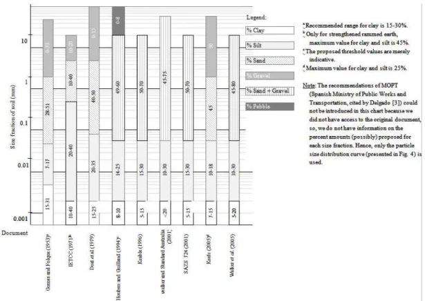
Figure 3 and Table 3 present some of the recommendations found in the literature for the PSD and MPS of rammed earth materials, respectively. It may be noted that while most documents indeed focus on both the PSD and the MPS (Gomes and Folque, 1953; IETCC, 1971; Keable, 1996; Keefe, 2005; Walker et al., 2005), there are some which consider only the PSD (Doat et al., 1979; Houben and Guillaud, 2006; Jiménez-Delgado and Cãnas-Guerreiro, 2007; Walker and Standard Australia, 2001) or only the MPS (New México Code, 2006). There is also the case of the New Zealand Code (1998) which is a performance-based code and, therefore, establishes no quantitative restrictions as regards the material composition. About the PSD it states, “the proportions of clay, silt and aggregate will vary
depending on the nature of minerals involved and the earth building medium being used”(p.15). About the MPS it states, “soils that contain aggregate large enough to impair the strength or homogeneous structural performance of
the wall shall not be used” (p.15).
The quantitative limits recommended for the PSD and MPS varies significantly among references, as seen in Fig. 3 and Table 3. Furthermore, the indicated partial size thresholds are not always comparable because: (i) in five out of the nine cases, the percentage of sand and gravel are given together; (iii) different documents often refer to different test procedures whose sieve apertures are not necessarily equivalent. Houben and Guillaud (2006) use ASTM standard D422-63 (2007); Walker et al. (2005) and Keefe (2005) use BSI standard BS 1377-2 (1990); Walker and Standards Australia (2001) use Australian Standard 1289; Doat et al. (1979) and Keable (1996) do not reference any standard, providing instead a brief description of the test methods. The document of IETCC (1971) includes just a short description of a procedure to determinate the percentage of fine particles (clay and silt). SAZS 724 (2001) and Gomes and Folque (1953) do not reference any test method at all.
There is no agreement among references as to the size of partials in Figure 3.
Fig. 3. Recommendations concerning the PSD of soils for rammed earth construction
Table 3
Requirements concerning the MPS of soils for rammed earth construction Reference Maximum particle size (mm)
Gomes and Folque (1953) 20-25. May contain a percentage of no more than 20-25% of larger particles (up to 50 mm) IETCC (1971) 20
Keefe (2005) 20 New Mexico Code (2006) 38.1
Walker et al. (2005) Often limited to 10-20. However, particles over 50-100 mm have been successfully used.
4.2. Methods
The PSD of the six studied rammed earth materials was measured following the methods indicated in LNEC Specifications E239 (1970) and E196 (1966): respectively, wet sieving of the coarse fraction (pebbles, gravel and sand) and sedimentation of the fine fraction (silt and clay).
The earth materials were previously prepared following LNEC Specification E195 (1966). To assume homogeneous material in the field of the samples used in the PSD determination, this specification defines the size of those samples as function of the MPS. For example, for a material whose MPS is 50.8 mm, it is necessary at least 4000 g of retained material on the 2 mm sieve (ASTM sieve No. 10).
Wet sieving (Specifications E239, 1970) involves washing the material through the 2 mm sieve. Afterwards, the retained material is oven dried and then dry-sieved through a defined series of sieves. The material that had passed the 2 mm sieve is placed in a cylindrical cup with a dispersing agent to disaggregate the particles of clay. After one hour, the suspension is washed through a 0.074 mm sieve (ASTM sieve No. 200). The retained material is oven dried and then dry-sieved.
their density. It consists in measuring at set intervals, using a hydrometer, the density variations that arise during a sedimentation process. The method requires, therefore, that the density of the different particles is known or can be assumed. Values for the density of soil particles are given, for example, by Portuguese Standard NP 83 (1965).
4.3. Results and discussion
The PSD curves obtained for the six case studies can be seen in Fig. 4. They show that the soils have a uniform particle size distribution (PSD nomogram with more or less constant slope), with the possible exception of Av and CZ which present a sharper slope in the central area. In the Av soil, this sharper slope concerns the particle sizes between 0.2-2 mm, which is characteristic of a high percentage of sand. The CZ soil shows a sharper slope for the 0.04-0.4 mm, which suggests the presence of a high percentage of coarse silt and fine to medium sand. As mentioned in the section 4.1, a uniform PSD is expected to result in higher density and, thus, higher mechanical resistance and durability. However, it is not possible to foreseen the exact consequences of the inhomogeneities found in soils Av and CZ.
Fig. 4. PSD nomograms and maximum particle size of the six rammed earth materials
Figure 5 compares the PSD of the six case studies to the lower and upper limits indicated by four of the surveyed references. This figure shows that:
the limits of MOPT (1992) are the widest; they cover all the studied materials, except for the particles larger than 60 mm in the VC material;
the limits of Walker and Standards Australia (2001) are the most restrictive for the larger particles (sands and gravels) and, because of that reason, they would exclude the Av material; the PD material would also be excluded, due to a too high percentage of fine particles, because the limits of Walker and Standards Australia (2001) are, also in this respect, a bit more restrictive than those of MOPT (1992);
the limits of SAZS 724 (2001) and Houben and Guillaud (2006) are relatively similar and, in general, the most restrictive for the smaller particles; the PD and VC materials are above the upper thresholds in the clay and silt zones; it should, however, be noted that Houben and Guillaud (2006) state that their limits of PDS are merely indicative.
Fig. 5. PSD nomograms showing the results of the six rammed earth materials and recommended limits for the PSD
Despite the above mentioned non-conformities, it is interesting that the six analysed rammed earth materials are, broadly speaking, within (or at least very close to) the PSD limits specified by the four references (Fig. 5). This could be remarkable because the earth materials used in the six buildings were chosen (a long time ago) most likely among those locally available, as discussed in section 3.1, rather than selected or corrected with basis on technical specifications. However, given the wide PSD limits, it is likely that many soils fall in those limits.
However, the same does not happen with the maximum particle size (MPS), which indicates a critical discrepancy between modern recommendations and the characteristics of old rammed earth materials from Alentejo region. Comparing the MPS of the six analyzed materials (Fig. 4) to the limits in Table 3, all the materials (except Av) fall outside, of the limits recommended. Indeed, most references discourage the use of large particles. Walker et al. (2005), for example, though indicating that large particles have been successfully used in rammed earth construction (Table 3), state in the same document, “increasing the proportion of larger particles increases the risk of surface defects such as ‘boniness’ and friable edges, and reduces compressive strength of the material” (p.37). Patty and Minium (1933), as referred by Maniatidis and Walker (2003), conclude that increasing the size of the gravel reduces the compressive strength of rammed earth. The situation is more positive when the MPS of the six analysed materials is compared to the limits given in the only Portuguese document (Gomes and Folque, 1953). In this case, only the VC soil falls outside the recommended limit.
The obtained experimental results indicate, therefore, that today’s international recommendations are not totally
applicable to traditional rammed earth used in Alentejo, particularly as regards the MPS. Also, the only national document (Gomes and Folque, 1953) seems better adapted to this regional type of earth material where very large aggregates have been successfully used.
5. Plasticity
5.1. Concept and threshold values
means of experimental parameters, the Atterberg limits. The most used limits are the plastic limit (PL), the liquid limit (LL) and a calculated parameter, the plasticity index (PI = LL - PL).
PL and LL are the water contents above which the soil changes its behaviour from semi-solid to plastic and from plastic to liquid, respectively. PI expresses the range of moisture content within which the soil remains plastic and provides information on the probable nature of the soil: clays usually have a higher PI than silty soils; a very low PI, close to zero, corresponds usually to sandy soils. The soils where the PL cannot be determined or is equal to the LL are considered non-plastic.
The LL and PI values recommended by different references for modern rammed earth are showed in Table 4. It can be seen that, nonetheless these references indicate (in some cases, quite) different thresholds, it is possible to find a common range of values, both for the LL (35-45%) and for the PI (15-29%).
These requirements are associated with test procedures which, despite not corresponding to the same standards, are essentially similar: the LL is determined by means of a manual Casagrande cup and the PL by rolling a thread of soil on a glass plate. Walker and Standards Australia (2001) mentions Australian Standard AS1289 (1995), and Walker et al. (2005) mention British Standard BS 1377-2 (British Standards Institution, 1990). Houben and Guillaud (2006) and Doat et al. (1979) do not cite any standard; however they described the test method similar to what was written in this section.
Table 4
Values for liquid limits and plasticity index for unstabilised rammed earth Reference LL (%) PI (%) Comments
Doat et al. (1979) 25 - 50 7-29 Threshold values 30 - 35 7-18 Recommended values Houben and Guillaud (1994) 25 - 46 2-30 Threshold values
30 - 35 12 - 22 Recommended values Walker and Standard Australia (2001) 35 - 45 15-30
Walker et al. (2005) 45 2-30
5.2. Methods
The LL and LP were determined in accordance with Portuguese standard NP 143 (1969) whose test method is similar to those mentioned by the four documents indicated in Table 4.
The tests are carried out on the soil fraction that passes the 0.42 mm sieve (No. 40 ASTM).
The LL is measured using a manual Casagrande cup. The material is mixed with water and placed in the metal cup of the apparatus. With a spatula, the material is then flattened and a v-shaped groove made in the centre. During the test, the cup is repeatedly dropped from a height of 1 cm and the number of blows required to close the groove for about 1 cm registered. The procedure is repeated for different soil moisture contents. The LL is the moisture content at which the groove is closed under the influence of 25 blows.
The PL is the moisture content at which the soil begins to crumble when rolled between the palm of the hand and a glass plate into a cylindrical thread of about 3 mm diameter. The value of PL is the average of the moisture content in four samples of each soil.
5.3. Results and Discussion
Table 5
Liquid limit and plasticity index of the materials Materials LL (%) PI (%)
Av 14.8 -
PD 41.2 16.1 VC 46.1 19.4
CZ 17.0 -
Cl 35.5 13.5
Ar 26.0 6.0
When the obtained values are examined in the light of the threshold values in Table 4, it is concluded that the six materials can be divided in three main groups:
PD, VC and Cl have the higher LL values (between 36% and 46%) and a medium PI (between 14% and 19%). Broadly speaking, the values obtained for the two parameters agree with the recommendations indicated in Table 4 - the LL of the VC soil is only slightly above the upper thresholds of Walker and Standards Australia (2001) and Walker et al. (2005) and the PI of Cl only a little bellow the lower threshold of Walker and Standards Australia (2001).
Ar is an intermediate situation: the LL (26%), though low, is still within the thresholds set by three references (Doat et al., 1979; Houben and Guillaud, 2006; Walker et al., 2005); the PI is also low but agrees with the limits set by two references (Houben and Guillaud, 2006; Walker et al., 2005) and is only a little bellow the lower limits set by a third reference (Doat et al., 1979).
Av and CZ are a different case, since they fall farther from the indicated limits. Their LL is quite low (between 15 and 17%). These values are acceptable only for Walker et al. (2005) who, in contrast with the general trend of imposing both an upper and a lower threshold for the LL, sets only an upper threshold for this quantity. Furthermore, it was not possible to measure the PL of either of these soils, which means they are non-plastic. Therefore, their PI could not be determined, which does not agree with the recommendations of any of the surveyed documents. Indeed, non-plastic soils are today considered unsuitable for rammed earth construction. In spite of that, the existence of buildings with such a long life (even after being abandoned) and the present experimental results show that non-plastic soils have been successfully used in rammed earth construction in the Alentejo region.
6. Compaction
6.1 Concept and threshold values
The Proctor compaction test is widely used for characterizing construction soils, including rammed earth. It provides pairs of values of the maximum dry density (dmax) and the optimum moisture content (OMC) of the soil.
cannot be properly squeezed (Keable, 1996). Walker and Standards Australia (2001) also mention a direct improvement in the strength and durability with increasing density. To achieve maximum density the soil should be compacted at the OMC.
However, the compaction of rammed earth soils is rarely addressed in normative documents, as seen in Table 1. Among the thirteen surveyed documents, only Houben and Guillaud (2006) mention this property. Based on values of the compaction energy and the corresponding moulding moisture content of the soil, Houben and Guillaud (2006) indicate a range of values for the OMC of 3.5% to 14% and dry density between 1750 kg/m3 and 2000 kg/m3.
6.2. Methods
The Proctor test was carried out according to ASTM standard D698-07 (2007). It consists of compacting a soil sample with known moisture content into a cylindrical mould and repeating the procedure at least four times (preferably five determinations) for different moisture contents. The obtained pairs of values (moisture content, dry density) allow drawing the compaction curve from which it is possible to determine the maximum dry density (dmax). The moisture content that corresponds to dmax is the optimum moisture content (OMC).
A cylindrical steel mould with 101.6 mm inner diameter and 116.4 mm height is used in the test. The soil samples are composed by material that passes the 4.75 mm sieve (No. 4 ASTM sieve) and in an amount of about 2.3 kg. Compaction was performed with a standard weight of 2.447 kg that falls from a normalized height of 304.8 mm. The samples include 3 layers of equal thickness, each layer being struck 25 times.
6.3. Results and Discussion
The results of the Proctor compaction test are presented in Table 6.
Table 6
Results of the Proctor compaction test of the materials Materials* OMC (%) dmáx (kg/m3)
Av 8.0 2018 PD 17.8 1733 VC 21.5 1651 CZ 11.3 1600 Cl 15.6 1814
*The test was not performed on the Ar sample because sufficient material could not be collected.
As seen, the obtained results show that none of the analyzed materials fits in the indicated ranges proposed by Houben and Guillaud (2006). PD, VC and Cl have an OMC above the indicated upper limit. VC, CZ and PD have dry densities that are below the lower limit, and Av has dry density above the upper limit according to (Houben and Guillaud, 2006). However, despite the age of the buildings from where the materials were sampled show that, at least for these regional rammed earth materials, the admissible value range can be enlarged.
7. Linear shrinkage
7.1 Concept and threshold values
cracks, which can give rise to water penetration, loss of strength and material disintegration. Shrinkage is mostly due to the presence of clay in the soil, so it strongly depends on the quantity and type of clay.
For earth materials, shrinkage is commonly evaluated by the Alcock´s test, also designated linear shrinkage test or shrinkage box test (Guillaud, 2008; Houben and Guillaud, 2006; Jiménez-Delgado and Cãnas-Guerreiro, 2007; Maniatidis and Walker, 2003). This test consists in filling a rectangular box of standard dimensions with soil at certain moisture content, letting it dry under specific environmental conditions and then measuring the reduction in length of the material in the box.
Requirements for the maximum shrinkage of rammed earth materials were identified in the surveyed literature (Houben and Guillaud, 2006; Keable, 1996; Keefe, 2005; Lehmbau Regeln, 2009; NZS 4298, 1998; Walker and Standard Australia, 2001) and are presented in Table 7. Although all these requirements are based on Alcocks’s test
method, quite significant variations of experimental procedures were found to exist: the box dimensions, the particle-size fraction and water content of the material used in the test, the duration of the drying period and the environmental conditions. The requirements themselves were also found to differ, sometimes significantly, from document to document. Indeed, as seen in Table 7, even when the test procedures are fairly similar, the threshold values can be quite scattered, reaching a difference of as much as 40 times, as it happens between the values of the New Zealand Standard (NZS 4298, 1998) and the German Lehmbau Regeln (Lehmbau Regeln, 2009).
Table 7
Recommendations and requirements for linear shrinkage test Reference
Box dimensions Water content Material Drying Maximum linear shrinkage (%) Keable (1996) 60cm×4cm×4cm Optimum moisture content Same material than in the wall 3 days in the sun 2a
NZS 4298 (1998) 60cm×5cm×5cm Same moisture content than in the wall
Same material than in the wall 7 days with the sample covered by a plastic sheet; 21 days in the air, out of direct sun light
0.05
Walker and Standard Australia (2001)
60cm×4cm×4cm Optimum moisture content Size fractions 6.00 mm Sample with 2-2.5 kg
3-7 days in the sun 2.5b
Keefe (2005) 60cm×5cm×5cm Optimum moisture content Same material than in the wall Until complete drying 0.25
Lehmbau Regeln (2009) 60cm×5cm×5cm Not mentioned Remove the coarse fraction (quantitative values are not specified)
Until complete drying 2
a For higher shrinkage values, the reference recommends adding a certain percentage of cement or of low clay content soil (sand/aggregate).
b For stabilized rammed earth with 4-6% cement content; the document provides threshold values for cement contents from 4-6% to 10%; the threshold value increases with the
cement content.
7.2. Methods
The linear shrinkage of the earth materials collected in the six studied buildings was measured following approximately the procedure proposed by Walker and described in Walker and Standards Australia (2001). This procedure was chosen because it specifies the water content the soil should have and limits the size of the aggregates contained in the tested sample. Indeed, the large size of the aggregates present in some of the six studied cases (Fig. 4) would not be compatible with the small size of the shrinkage box. Therefore, it was not possible to test exactly the rammed earth material but a fraction (Keable, 1996; Keefe, 2005; NZS 4298, 1998).
Boxes made of film-faced plywood were used in the tests. Their inner surfaces were slightly oiled with a release agent to prevent adhesion of the dry soil, which could limit its length reduction, as observed in a series of preliminary experiments. In each box, a soil sample with 2.0 kg to 2.5 kg of the material passing the 6.30 mm sieve (No. 1/4”
The boxes were filled with soil at the optimum moisture content in three layers, each layer being pressed to release the entrained air, and the final surface was smoothed. In the procedure of Walker and Standards Australia (2001), the filled-in mould is exposed to direct sunlight for 3 to 7 days. However, in the present case, the test was conducted in rainy days, so that sunlight exposure was not possible. It was therefore necessary to modify the procedure: drying was carried out in a ventilated oven at 40°C until constant mass, that is, until the mass loss during a 24 hour interval was less than 0.1% of the dry mass, which had the advantage of giving the test a more standardized character.
The linear shrinkage, S, was then calculated using the following expression (1):
% 100mould soil mould
L L L
S (1)
where Lmould is the (internal) length of the mould and Lsoil the total length of the dry soil sample.
7.3. Results and Discussion
Drying shrinkage caused cracking of the material in the moulds, which therefore broke into segments. This was probably due to some residual adherence of the soil to the mould and a continuous and fast drying. In order to determine the total length of the soil sample at the end of the test, when drying was complete all the segments were pushed to one end of the box.
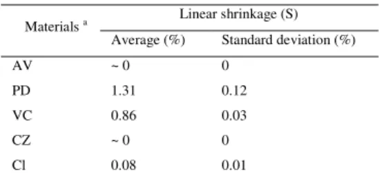
Table 8 shows the average shrinkage values obtained for the six case studies and the corresponding standard deviation. As seen, the shrinkage of the analysed soils is in general low, never exceeding 2.5%, the maximum recommended shrinkage value of Walker and Standards Australia (2001) (Table 7). The standard deviation shows that the variability of the obtained linear shrinkage values is negligible.
There seems to be a linear correlation between the linear shrinkage and the percentage of clay (Fig. 6), which is consistent with the XRD finding of only non-expansive clays in all the samples (Table 2).
Table 8
Results of the linear shrinkage test of the materials
Materials a Linear shrinkage (S)
Average (%) Standard deviation (%)
AV ~ 0 0
PD 1.31 0.12
VC 0.86 0.03
CZ ~ 0 0
Cl 0.08 0.01
aThe test was not performed in the Ar sample because sufficient material could not be collected
8. Organic content
8.1 Concept and threshold values
Besides mineral matter, water and air, soil is composed of organic matter, which includes that derived from living organisms (animals, plants, bacteria). It is usually accepted that the most appropriate soil for construction comes from the subsoil (also called B horizon) which is the layer immediately below the surface soil. The subsoil contains higher percentage of minerals and lower content of organic matter (Walker and Standards Australia, 2001; BS 1377-3, 1990). Indeed, earthen buildings, where the percentage of organic matter is significant, are more likely to present anomalies caused by the presence of moisture or biodeterioration processes.
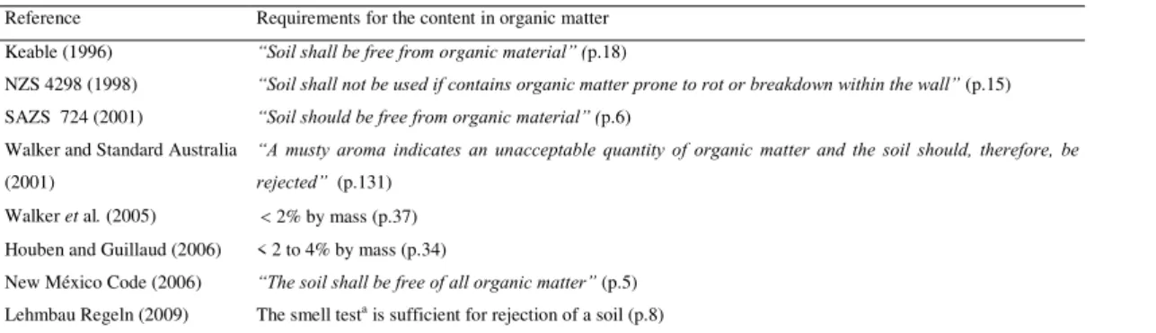
Table 9 presents the requirements indicated by different references for the organic content of soils for rammed earth construction. As seen, there is a wide consensus that soils with large quantities of organic matter (either microscopic or macroscopic) should not be used. However, quantitative threshold limits are rarely indicated.
Table 9
Requirements for organic matter
Reference Requirements for the content in organic matter Keable (1996) “Soil shall be free from organic material” (p.18)
NZS 4298 (1998) “Soil shall not be used if contains organic matter prone to rot or breakdown within the wall” (p.15) SAZS 724 (2001) “Soil should be free from organic material” (p.6)
Walker and Standard Australia (2001)
“A musty aroma indicates an unacceptable quantity of organic matter and the soil should, therefore, be rejected” (p.131)
Walker et al. (2005) 2% by mass (p.37) Houben and Guillaud (2006) < 2 to 4% by mass (p.34)
New México Code (2006) “The soil shall be free of all organic matter” (p.5) Lehmbau Regeln (2009) The smell testa is sufficient for rejection of a soil (p.8)
aOrganic soil is identifiable by its strong smell of humus. The smell test should be performed immediately after extraction of the soil.
The two references that present quantitative threshold values (Walker et al., 2005; Houben and Guillaud, 2006) are
also the only ones that indicate detailed experimental procedures for measuring the soil’s organic content. But there is
no consensus as to the type of procedure. Walker et al.(2005) recommends the method of BS 1377-3 (1990), which uses dichromate oxidation and is normally known as the Walkley and Black method. Houben and Guillaud (2006) reference an expedited test which consists in mixing the soil with a solution of sodium hydroxide and then comparing the color of the mixture with that of a standard solution of tannic acid.
Another three references (Walker and Standards Australia, 2001; Lehmbau Regeln, 2009; Keable, 1996)
recommend accepting or rejecting a soil based on the results of smell tests. “A musty aroma”, “the strong smell of
humus” and “a musty smell” are the rejection criteria indicated by Walker and Standards Australia (2001), Lehmbau
Regeln (2009) and Keable (1996), respectively.
The recommendations of the remaining three documents (NZS 4298, 1998; SAZS 724, 2001; New Mexico Code, 2006) are very general, advising the rejection of soils that contain organic matter but not mentioning any experimental procedure to assess its presence or any rejection criterion.
8.2. Methods
ASTM D2974-07 (2007). Some changes had to be introduced to the original procedure because of the large aggregates present in some of the soils, to allow for the testing of the relatively small samples, compatible with a standard laboratory furnace. The protocol was adapted also to differentiate the larger organic matter (sticks and roots) present in the PD and Cl soils.
The experimental procedure was the following:
from each studied building, a sample mass of 2 to 3 kg material was randomly collected;
the material was oven-dried at 100 ± 5 ºC until constant mass and its total mass (MT) was then determined;
all visible organic matter larger than around 10 mm (sticks and roots, mostly) was removed and the total mass of thus organic material (Mvis) recorded;
the percentage of the large sized organic matter (OClarge) is given by (2):
% 100 arg T vis e l M M OC (2) the sample was then sieved using a 9.52 mm sieve (No. 3/8” ASTM sieve) and the mass (Mpass) of the passed material determined;
the passed material was then split up into smaller samples of approximately 200 g (mass of each sample, M200g); the organic content of these samples was determined by calcination according to the procedure of ASTM
D2974-07 (20D2974-07); five samples were used for each of the studied buildings; each sample was placed in a porcelain dish and then put inside a muffle furnace where the temperature was gradually brought (over a period of 2 hours) to 440 ± 22 ºC and maintained so until the specimens were completely ashed (that is, until no change of mass occurred after at least 1 hour at the maximum temperature); the mass (M200gC) of the calcinated sample was determined; the total content of small sized organic matter (OCsmall-ind) is given by (3):
T pass g gC g ind small M M M M M OC 200 200 200 ) ( 100
[%] (3)
the content of small sized organic matter (OCsmall) in each material corresponds to the average of the individual values (OCsmall-ind) obtained for the five small samples;
the total content of organic matter in a material (OC) is calculated by adding the values obtained for the small and the large sized organic matter as equation (4):
OCOCsmallOClarge
% (4)8.3. Results and Discussion
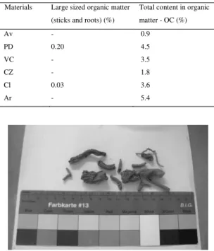
The content in organic matter of the analyzed materials is indicated in Table 10. When these values are compared to the limits (Table 9) recommended by Walker et al. (2005) or Houben and Guillaud (2006), it is seen that only the Av and CZ have clearly acceptable organic matter contents. The Ar material contains over 5% OC. The Cl and particularly the PD material contain large sized organic matter (Fig.7). But even if these large sized particles were removed, the percentage of organic matter of PD material would still be higher than 4% recommended by Houben and Guillaud (2006).
Organic matter content in the materials Materials Large sized organic matter
(sticks and roots) (%)
Total content in organic matter - OC (%)
Av - 0.9
PD 0.20 4.5
VC - 3.5
CZ - 1.8
Cl 0.03 3.6
Ar - 5.4
Fig. 7. Organic matter exceeding 10 mm length (case-study PD)
9. Salt content
9.1 Concept and threshold values
Soluble salts are one of the most damaging decay agents of porous building materials (Steiger and Siegesmund, 2007). The salts originate from ions (chloride, sulfate, nitrate or others) that migrate, dissolved in liquid water, in the pore network of the materials. Salt crystallization occurs as a result of evaporative processes or temperature changes that cause these solutions to supersaturate. Salt damage is due to the cyclic precipitation of salt crystals either on top of (efflorescence) or inside (subflorescence) the porous material. Subflorescence can induce internal stresses that overcome the mechanical strength of the porous material and, therefore, induce physical damage. Efflorescence does not constitute or cause material damage, though it may account for aesthetical and health problems. However, efflorescence can be redissolved, and reabsorbed into the material and eventually recrystallize as subflorescence.
Salt decay of earth constructions is still very poorly studied, most case-studies and research being devoted to classic building materials such as stone, mortars and ceramics. However, it is well known that soils can be an important source of salts. Sodium chloride, for instance, often arises from contamination with sea water or, due to human consumption of sodium chloride, with domestic residues (Hall and Djerbid, 2004b). Soil may also contain nitrates produced by the decomposition of organic matter from organic fertilizers, animal excrements, organic tissues or microorganisms. Soils can also contain sulfates, for instance, sodium (Zehnder and Arnold, 1989).
Soils that contain salt are, therefore, not suitable for earth construction. Accordingly, some references propose requirements concerning the salt content of earth building materials (Table 11). However, only two out of the five that address this property have recommended quantitative thresholds. The NZS 4298 (1998) sets a general requirement to reject the use of soils with damaging salts; Houben and Guillaud (2006) reference the potential harmfulness of just three types of sulfate salts (sodium, magnesium and calcium); the SAZS 724 (2001) advises very generally the rejection of soils containing salts such as sulphates. Quantitative requirements are set by Walker et al. (2005) and the New Mexico Code (2006), both establishing a maximum limit of 2% total salt content. However, only Walker mentions the test method to determine the salt content: BS 1377-3 (1990), which focuses on the sulfate, chloride and carbonate contents of soils.
All of these requirements are clearly too general (NZS 4298, 1998; SAZS 724, 2001), or lack justification as to the type of salts covered (Walker et al., 2005; SAZS 724, 2001; Houben and Guillaud, 2006), and the recommended threshold values (Walker et al., 2005; New Mexico Code, 2006). In fact, the establishing threshold value for the salt content of building materials is not straightforward. Indeed, salt decay derives from complex processes which are not yet fully understood and depend on a variety of dynamically interrelated factors, such as the type and content of salt, the environmental conditions (temperature, relative humidity and air velocity), the physical characteristics and moisture content of all the involved materials (porosity and pore size distribution, as well as the vapor and liquid transport properties), and the presence and characteristics of the coverings (plasters, renders, paints) .
Table 11
Requirements for salt content
Reference Requirements for salt content
NZS 4298 (1998) “Shall not be used soils containing water soluble salts to an extent which will impair the
strength or durability of the wall” (p.15)
SAZS 724 (2001) “Soil should be free from salts such as sulphates”(p.6) Walker et al. (2005) 2% (p.37)
Houben and Guillaud (2006) “Sulphates of sodium, magnesium and calcium are dangerous to soils used in earth construction, since they crystallize, making it easily broken”(p.23)
New México Code (2006) 2% (p.5)
9.2. Methods
In the present case, the salt content of the materials was evaluated by means of the hygroscopic moisture content (HMC) method (Gonçalves, 2007; Gonçalves and Rodrigues, 2006; Gonçalves et al., 2006). This method is based on the following facts:
the HMC of soluble salts is much higher than that of porous building materials in general, which allows assuming that all the hygroscopic moisture a sample attracts from the air derives totally from the hygroscopic action of the salt it contains;
the HMC increases linearly with the salt content of the material.
In the present case of samples collected from buildings, where the type of salt possibly present in the materials is not known, the HMC method allows only an approximate evaluation of the salt content.
The HMC is calculated by the following expression (5), where mdry is the dry mass of the sample and ms is the mass at hygroscopic equilibrium:
% 100dry dry s
m m m
HMC (5)
Two reference samples which were composed of about 0.5 g of sodium chloride (NaCl) were also prepared and tested. The HMC of these reference samples (HMCNaCl) allows the determination of the relative humidity in the climatic chamber:
- first, the molality m (mol/kg) of the solution that forms at hygroscopic equilibrium is calculated by the following expression (6), where Msalt is the molar mass of the salt (the molar mass of NaCl is 0.05844 kg/mol);
100 [ / ]
kg mol M HMC m
salt NaCl
(6)
- the water activity, aw, of a NaCl solution with molality, m, is obtained from a table of thermodynamic parameters for electrolyte solutions (Robinson and Stokes, 2002), which gives the values of aw for different molalities;
- the actual RH in the climatic chamber corresponds to the percent value of aw, that is: HR ≡ 100aw.
The salt content of the rammed earth material samples was then estimated assuming they were contaminated with a single salt. This estimation was carried out for two different salts - NaCl and Na2SO4 - which correspond to one of the most and one of the least hygroscopic salts commonly found. Therefore, there is a reasonable likelihood that the calculated NaCl and Na2SO4 contents correspond to the lower and upper limits, respectively, of the possible range of salt contents of the materials.
Estimation of the salt content is done in a different way for NaCl and Na2SO4 because the HMC of the reference samples can be used as a direct measure for NaCl. The HMC of salt contaminated materials varies linearly with their salt content (Gonçalves and Rodrigues, 2006); thereby the (theoretical) NaCl content of the soils can be directly calculated by a simple proportion rule considering: (i) the HMC of a sample with 100% salt content (the average of the HMC values obtained for the reference samples); (ii) the HMC of a sample with 0% salt content, which is assumed to be zero.
For Na2SO4, no reference samples were tested. Therefore, estimation of the salt content has to be based on tabulated values of thermodynamic parameters. Since appropriate values were not available for the water activity, aw, of Na2SO4 solutions, another thermodynamic quantity - the osmotic coefficient - had to be used (Robinson and Stokes, 2002). The osmotic coefficient, Φ, is related to aw by equation 7:
ln(aw)Mm
(7)
where ν is the stoichiometric coefficient, a parameter that expresses the number of moles of ions produced when a mole of solute molecules is dissociated (ν=3 for Na2SO4).
The values of Φ given in the tablefor each molality, m, are converted into aw values through equation 7. Then, the value of aw that corresponds to the actual RH in the chamber is used to obtain, by linear interpolation, the respective value of m. With that value of m and the molar mass of Na2SO4 (which is 0.14205 kg/mol), the HMC of a sample with 100% Na2SO4 content is calculated by means of equation (7). Finally, the Na2SO4 content of each soil sample is obtained through a proportion rule, assuming that the HMC of a sample with 0% Na2SO4 content is zero.
The HMC of the six rammed earth materials and the corresponding theoretical contents in NaCl and Na2SO4 are presented in Table 12. It can be seen that the theoretical contents in NaCl and Na2SO4 are relevant only for the Ar material, collected from the only studied building in an urban setting. Indeed, even considering the presence of a salt as hygroscopic as NaCl, the salt content of the soil is higher than 2% which is the limit indicated by Walker et al. (2005) and the New México Code (2006).
The obtained results indicate that salt content of the other five rammed earth materials is insignificant. Indeed, though for the calculations presented in the previous section the HMC of the base-material (earth) is assumed to be zero, porous building materials are in reality responsible for some hygroscopic absorption (Gonçalves and Rodrigues, 2006), particularly in cases of materials containing clay. Therefore, the salt content of these five rammed earth materials is likely to be even lower than estimated.
In the case of the Ar material, the clay has low activity (Table 2), so it is likely that the high hygroscopic absorption corresponds, indeed, to a relevant presence of salt. It is not known, however, whether the salt was present in the original soil used in the construction or resulted from a latter deposition.
Table 12
Hygroscopic moisture content (at 20ºC and 96% HR) and theoretical salt content of the materials Materials HMC (%) Estimated contents of salt, assuming
the presence of a single salt (%) Average Standard
deviation
NaCl Na2SO4
Av 4.2 0.3 0.24 0.55
PD 5.4 0.1 0.31 0.72
VC 4.7 0.2 0.27 0.62
CZ 1.2 0.1 0.07 0.16
Cl 3.1 0.1 0.18 0.41
Ar 42.6 1.0 2.46 5.73
Reference samples (100% of NaCl)
1763.6 (corresponds to an actual RH of 96.8%)
21.8 - -
10. Conclusions
This study addressed the characterization of unstabilised rammed earth material, in a sample of old walls in a Portuguese region where that building technique is very common and its comparison with a bibliographic review. The work included:
a literature survey to identify the key properties of unstabilised rammed earth materials: particle size distribution (PSD); maximum particle size (MPS); plasticity; linear shrinkage; compaction; organic content and salt content; the mentioned test procedures and the threshold limits indicated by different documents for the above mentioned properties;
the selection of the test procedures for the experimental analysis and the characterization of the rammed earth materials collected from six rammed earth old buildings located in different regions of Alentejo, Portugal;
a discussion of the thresholds for each test in the light of the experimental results obtained for the six analyzed materials.
Five of the surveyed buildings are rural constructions where observation of the surrounding soil was possible and suggested that local earth, with minimum or no processing, was used to build the rammed earth walls.
- The particle size distribution of the six collected materials is, broadly speaking, within the considered threshold limits. However, the same does not happen with the maximum particle size, which seems to configure a critical discrepancy between modern recommendations and the characteristics of old rammed earth materials from Alentejo region. Indeed, five out of the six materials exceed the maximum recommended aggregate size. It is interesting that the only national document (Gomes and Folque, 1953), by admitting the possibility of using much larger aggregates (up to 50 mm), is better adapted to this regional type of earth material: in this case, only the VC soil would be rejected or needed to be previously sieved.
- As to plasticity, the results show that four out of the six analyzed materials are indeed in agreement with (PD, VC and Cl) or very close to (Ar) the thresholds set by all or by three, respectively, of the surveyed documents. However, these results also reveal that non-plastic soils, where the LL is low and the PI could not be determined, have been successfully used in the remaining two cases (Av and CZ), despite this type of soil is widely considered unsuitable for rammed earth construction.
- As regards the compaction, the Av material is the only that fits in the recommendations of the single document that addresses this property (Houben and Guillaud, 2006). For the remaining analyzed materials, these recommendations would lead to the use of molding moisture contents not very close to the OMC.
- The linear shrinkage of the six studied materials is low (practically nil in four cases) and never exceeds the identified maximum threshold values. This conclusion is consistent with the results of the XRD test where only non-expansive types of clay were indentified.
Nevertheless, some comments can be made on the linear shrinkage test method. All the surveyed references use variations of the so-called Alcocks’s test method but there are problems regarding the practicability of the
experimental procedure:
in the cases where the coarse fraction is not removed, the procedure is not applicable to soils with large aggregates such as those found in the six Alentejo old buildings due to the reduced size of the box;
drying in non-controled conditions, at ambient temperature or even under direct sunlight, is indicated in most cases, which may compromise the reproducibility of the experimental results; in addition, exposure to direct sunlight can be impracticable in winter conditions.
- Concerning the content in organic matter, the values obtained for four of the six materials clearly exceed the identified threshold limits. Furthermore, two of these materials (PD and Cl) contain relevant amounts of large sized organic matter (sticks and roots), which is consistent with the above stated observation that at least sometimes the soils were subjected to little or no processing before being used to build the rammed earth walls.
It is worth noting the extreme variability of the requirements and test methods that concern this property. Three documents give only general advice as to reject soils that contain organic matter. Three other references
recommend simple smell tests. A “musty aroma” (Walker and Standards Australia, 2001), “the strong smell of
humus” (Lehmbau Regeln, 2009) and “a musty smell” (Keable, 1996) are the indicated rejection criteria. Only two
documents present quantitative thresholds (Walker et al., 2005; Houben and Guillaud, 2006) which coincide in value (organic content lower than 2% by weight). However, none of the test methods they indicate is appropriate for testing soils with large aggregates, as it happens with the six analysed materials from Alentejo.
threshold values (maximum of 2% salt content) but only one refers the test procedure which, however, addresses only three types of ion: sulfate, chloride and carbonate. Authors believe that the hygroscopic moisture content (HMC) test method, as used in the present case, might be a valuable alternative.
Summarizing, this work highlights the advantages of taking into account the performance and characteristics of existing constructions, as a basis for the establishment and further refining of threshold values for the key properties of rammed earth soils, as well as for an appropriate definition of the associated test methods. In particular, it indicates that it is appropriate and useful to regionally validate the requirements and eventually adjust them to the specificities of local materials which have been successfully applied. This was clear for the present six Alentejo rammed earth materials but it might happen also, in relation to the same or to different soil properties, with the materials used for rammed earth construction in other points of the globe. Indeed, local soils are the most appropriate for a sustainable construction, unstabilized or, when needed, stabilized. That is one of the main factors why modern earth construction has its justification and future.
Acknowledgement
This work was carried out at the National Laboratory for Civil Engineering (LNEC), in Lisbon. M. I. Gomes was supported by a doctoral grant from the Portuguese Foundation for Science and Technology (FCT).
We are grateful to many people from the Geotechnics and the Materials Departments of LNEC who collaborated in the experimental work. We would like to thank, in particular, José Costa, João Júnior and João Ribeiro.
We are also thankful to the owners of all buildings that allowed the collection of material. To Raul Almeida and the architects Ines Fonseca and Florbela Vitorino who helped in the search of suitable buildings in Odemira, Avis and Arraiolos.
References
AS 1289. 1995. Methods of Testing Soils for Engineering Purposes. Standards Australia: Sidney.
ASTM D422-63. 2007 (Reapproved). American Society for Testing and Materials: Standard test method for
particle-size analysis of soils. ASTM: United States.
ASTM D698-07. 2007. American Society for Testing and Materials: Test methods for laboratory compaction
characteristics of soil using standard effort. ASTM: United States.
ASTM D2974-07. 2007. American Society for Testing and Materials: Test methods for moisture, ash and organic
matter of peat and other organic soils. ASTM: United States.
BS 1377-2. 1990. British Standards Institution: Soils for civil engineering purposes. Part 2: Classification tests. London.
BS 1377-3. 1990. British Standards Institution: Soils for civil engineering purposes. Part 3: Chemical and
electro-chemical tests. London.
Bui, Q.B., Moral, J.C., and Reddy, B.V.V. 2009. Ghayad W. Durability of rammed earth walls exposed for 20 years to natural weathering. Building and Environment, 44: 912-9.
Cid, J., Mazarrón, F.R., and Cañas, I. 2011. Las normativas de construcción com tierra en el mundo. Informes de la Construcción, 63, 523: 159-69.
Doat, P., Hays, A., Houben, H., Matuk, S., and Vitoux, F. 1979. Construire en terre. CRATerre - Centre de Recherché et d´Application - Terre. École d'Architecture de Grenoble, France.
Gonçalves, T.D. 2007. Salt crystallization in plastered or rendered walls, PhD Thesis. LNEC and IST, Technical University of Lisbon, Portugal. http://www-ext.lnec.pt/LNEC/bibliografia/DM/TG_PhDthesisMar2008.pdf.
Gonçalves, T.D., and Rodrigues, J.D. 2006. Evaluating the salt content of salt-contaminated samples on the basis of their hygroscopic behavior. Part I: Fundamentals, scope and accuracy of the method. Journal of Cultural Heritage, 7: 79-84.
Gonçalves, T.D., Rodrigues, J.D., and Abreu, M.M. 2006. Evaluating the salt content of salt-contaminated samples on the basis of their hygroscopic behavior. Part II: Experiments with nine common soluble salts. Journal of Cultural Heritage, 7: 193-200.
Guillaud, H. 2008. Characterization of Earthen Materials. In Terra Literature Review - An overview of research in
earthen architecture conservation. Edited by Avrami E, Guillaud H, Hardy M. The Getty Conservation Institute, Los Angeles, United States, 21-31.
Hall, M., and Allinson, D. 2009. Analysis of the hygrothermal functional properties of stabilized rammed earth materials. Building and Environmental, 44: 1935-42.
Hall, M., and Djerib, Y. 2004a. Atlantic Moisture ingress in rammed earth: Part 1 - the effect of soil particle-size distribution on the rate of capillary suction. Constr Build Mater, 18: 269-280.
Hall, M., and Djerbib, Y. 2004b. Rammed earth sample production: context, recommendations and consistency. Constr Build Mater. 18(4): 281-6.
Houben, H., and Guillaud, H. 2006. Earth construction: a comprehensive guide. London: Intermediate Technology publications, (1st edition 1994).
IETCC. 1971. Obras de Fábrica. Prescripciones del Instituto Eduardo Torroja - PIET - 70. Madrid: Instituto Eduardo Torroja de la Construcción y del Cemento.
ISO/IEC Guide 2. 2004. Standardisation and related activities - General vocabulary. Geneva, Switzerland: International Organisation for Standardisation (ISO).
Jaquin, P.A., Augarde, C.E., and Legrand, L. 2008. Unsaturated characteristics of rammed earth materials. In 1st European Conference on Unsaturated Soils. E-UNSAT, Durham, UK, 2-4 July. Toll et al. (Eds), Taylor and Francis, London.
Jiménez-Delgado, M.C., and Cãnas-Guerrero, I. 2007. The selection of soils for unstabilised earth building: a normative review. Constr Build Mater, 21: 237-51.
Keable, J. 1996. Rammed earth structure - A code of pratice. Intermediate Technology Publications. London.
Keefe, L. 2005. Earth building - methods and materials, repair and conservation. Taylor & Fancis Group. USA and Canada.
Lehmbau Regeln. 2009. Begriffe, Baustoffe, Bauteile. Dachverband Lehm e.V. (Hrsg.), Germany: Vieweg & Teubner, 3, überarbeitete Auflage. Praxis. Wiesbaden, Germany.
Maniatidis, V., and Walker, P. Review of Rammed Earth Construction. DTi Partners in Innovation Project - Developing Rammed Earth for UK Housing. Natural Building Technology Group, Department of Architecture & Civil Engineering, University of Bath, 2003.
MOPT. 1992. Bases Para el Disenõ y Construcción con Taipial. Madrid, Spain, Centro de Publicaciones, Secretaría General Técnica, Ministerio de Obras Públicas y Transportes.
New México Code. 2006. New México Earthen Building Materials Code 14.7.4. Santa Fé, NM: Construction Industries Division (CID) of the Regulation and Licensing Department.
NP 83. 1965. IGPAI - Repartição de Normalização. Portuguese Standard. Soils. Determination of the density of