Universidade de Lisboa
Faculdade de Ciências
Departamento de Física
Development of a beamline high speed
atomic force microscope and tuning of a
mechanical oscillator via a force
feedback strategy
Miguel Vargas Vitorino
Dissertação
Mestrado Integrado em Engenharia Física
Universidade de Lisboa
Faculdade de Ciências
Departamento de Física
Development of a beamline high speed
atomic force microscope and tuning of a
mechanical oscillator via a force
feedback strategy
Miguel Vargas Vitorino
Dissertação
Mestrado Integrado em Engenharia Física
Orientador: Doutor Mário Rodrigues
Contents
Abstract ix Sumário xi Resumo xiii Acknowledgments xvii 1 Introduction 11.1 A little giant called Atomic Force Microscope . . . 2
1.2 "Bringing light into the nanoworld" . . . 8
1.3 The High Speed X-AFM . . . 11
2 The Project of the High Speed X-AFM 15 2.1 What does it mean to go on a beamline? . . . 16
2.2 What does it mean to go high speed? . . . 20
2.2.1 Cantilever . . . 22
2.2.2 Scanner . . . 23
2.2.3 Electronics and Control . . . 25
2.3 The Design of the Instrument . . . 28
2.3.1 The Approach and a General View . . . 28
2.3.2 The Scanner . . . 30
2.3.3 The Detection Mechanism . . . 35
2.3.4 The Cantilever Holder . . . 42
2.3.5 Movement in the HSX-AFM . . . 44
2.3.6 Some other parts and the Final Assembly . . . 48
3 The Construction of the HSX-AFM and first tests 51 3.1 Building an AFM and the pursuit of the first image . . . 51
4 "And now, for something completely different..." 67
4.1 "Giant resonance tuning of micro and nanomechanical oscillator" 67
5 Conclusions and Outlook 79
Bibliography 84
A Datasheets and references of various components 93
A.1 H-610 Miniature Hexapod . . . 93
A.2 Lateral Piezoactuators P885.11 . . . 93
A.3 Piezotube PD080 and Cantilever Exciting Piezoactuator PL022 93 A.4 Aspherized Lenses . . . 93
A.5 Right Angle Mirror . . . 93
A.6 PiezoLegs Motor . . . 93
A.7 Sliding Plate . . . 93
A.8 Smaract Assemblies . . . 93
A.9 Laser and Optical Fiber . . . 93
B Frequency Study of Scanner Motion 109
List of Figures
1.1 Representation of a cantilever used in an AFM measurement. . 4 2.1 xz profile sketch of the experimental Setup of ID13. The main
components that constrain the design of the AFM can be seen: the Optical Microscope is placed at ddown
x from the sample, while the lead foil distances dup
x from it. The profile of the X-Ray Optics support can also be seen, as well as a represen-tation of the cone which is to be left free in order to allow wide angle scattering measurements. . . 18 2.2 Diagram representing the feedback loop in amplitude
modu-lation AFM. Each element in the loop has an associated time constant, which limits the maximum frequency attainable in measuring the topography at one single point in the sample, floop. . . 21 2.3 (a) high speed scanner for Ando’s HS-AFM. Taken from [1];
(b) high speed scanner built in SSL for use with grazing-incidence X-Rays Experiments. . . 25 2.4 High speed scanner used in Hansma’s HS-AFM, taken from
[2] and [3]. . . 26 2.5 (a) design strategy of the HSX-AFM: a schematics of the
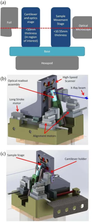
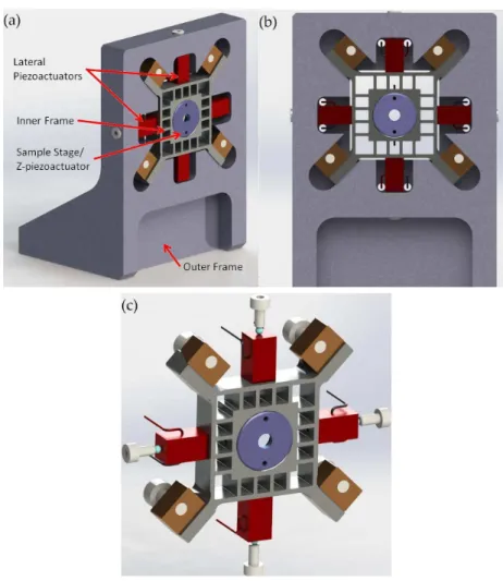
ap-proach and different parts; (b) final version of the model; (c) another perspective of the model; some of the main parts of the AFM are detailed. . . 29 2.6 (a) custom-made, high speed scanner created for HSX-AFM;
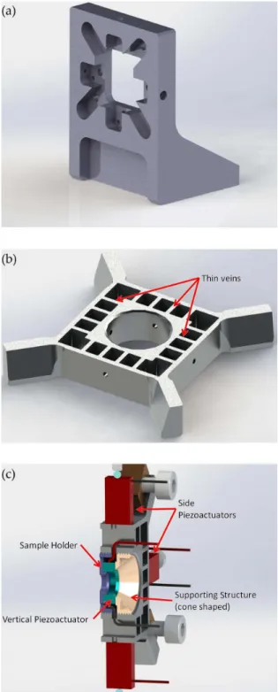
(b) front view of the scanner; (c) inner skeleton of the scanner. Some of the constituents of the scanner are detailed. . . 31 2.7 (a) scanner’s outer frame; (b) scanner’s inner frame; (c) details
of sample holder/vertical-stage. Some of the constituents of the scanner are detailed. . . 33
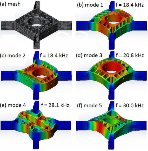
2.8 Frequency study performed for the inner frame of the scanner. (a) the solid mesh used to perform the simulation; (b)-(f) the first 5 modes of vibration, with the respective frequency of oscillation. To provide more accurate results, the fixtures and connections were done taking into account the ones in the assembly. . . 34 2.9 Schematics of the circuit implemented to drive each pair of
piezoactuators controlling the scanning motion of the sample. 35 2.10 The scanner of the HSX-AFM. It’s also seen the movable
as-sembly that controls its positioning, the base and the connect-ing plate to the hexapod, that will be detailed in this report further ahead. On the right, in gray, part of the BNC con-necting stage can be observed. . . 36 2.11 (a) The optical setup for focusing the laser beam on the
can-tilever backside. The geometry of the problem leads to a solu-tion that utilizes the space bellow the lead foil that is unused. The X-Ray beam is represented by the dashed orange line, and the laser beam by the red line. On the right, in brown, the sample, and in black, a representation of the cantilever. The whole system needs to have, in the region of the beam, A, thickness in the order of 10-12 mm, but some of this space is not usable, A-B, due to the apparatus necessary to hold the cantilever in the right fashion. (b) scheme of the focusing system used in the HSX-AFM (simulation with the software OpticStudio by Zemax). The light is collimated by the firstR lens and focused by the second. Their focal distances are cho-sen so the magnification of the system allows for a spot with the dimensions of the cantilever used. . . 39 2.12 Optical assembly designed for the HSX-AFM: (a) cross section
of the lenses holding assembly, together with the right-angle mirror; (b) section view of the whole piece; (c) complete piece; (d) details of the fiber holder. . . 41 2.13 Set of optical system and OSA for (a) original-sized OSA and
(b) machined-down one. . . 42 2.14 Optical assembly of the HSX-AFM: (a) the complete assembly;
(b) side view with the detail of the experimental setup of ID13; (c) detail of OSA aligned with the laser beam and cantilever; (d) the whole structure on top of the AFM base, together with the motorized stage that will position it. . . 43
2.15 Cantilever holder designed for the HSX-AFM: (a) front view, where we can see the cantilever chip, the OSA and the screw mechanism for removing the holder from the assembly; (b) side cut with the cantilever positioning system; (c) backside, where we can see the sliding mechanism; (d) the whole assembly with the motorized stage. Some of the constituents are detailed. . . 45 2.16 Scanner movement assembly: (a) PiezoLegs motor; (b) Sliding
plate; (c) the base of the scanner with the motor, the plate and the pre-loaded spring; (d) top view, with the scanner on top of the movement stage. . . 47 2.17 Base of the HSX-AFM (a) the two pieces interconnecting the
HS-AFM and the hexapod; (b) the bottom plate. . . 49 2.18 The model of the HSX-AFM: (a) isometric view and (b) side
view. . . 50 3.1 The first steps of the assembly of the AFM: (a) mounting the
scanner; (b) turning on the laser beam and a first attempt to focusing. . . 52 3.2 An example of the misalignment caused by the adaptation of
another motorized assembly. To increase the signal-to-noise ratio and perform better images these sources of error must be eliminated. . . 53 3.3 Offset of the fiber position, and its effect on the focus
po-sition: (a) original position of the fiber; (b) the position of the fiber for the several measurements performed; (c) effect of the offset in the focal position (simulation with the software OpticStudio by Zemax). . . 54R 3.4 Several pictures detailing the different steps of the alignment
procedure: 1 - the laser spot is placed on the cantilever chip; 2-3 the position with minimal spot size is found by moving the cantilever in x; 4 the cantilever is finally positioned on the focal point of the system. . . 55 3.5 The first fringes obtained with the instrument: the cantilever
is displaced by steps of 3 µm in x and afterwards is left to rest. The signal aquired by the photodector can be seen. After the observation of the fringes, a fast oscillation signal, a much slower periodic signal can be observed, indicating that the the distance between fiber and cantilever is slowly varying. . . 56
3.6 Amplitude and phase dependency of the cantilever frequency of excitation: (a) the first resonance curve obtained with the HSX-AFM; (b) the same experiment performed after a series of upgrades in the instrument. . . 57 3.7 (a) Results of the contact mode experiment performed on the
calibration grating with the HSX-AFM. Left: measured to-pography; Right: measured interferometer (error) signal. (b) measurement of the interferometer signal by pushing the can-tilever with the sample. . . 58 3.8 Single-strand DNA imaged with the HSX-AFM, topography
measurements. . . 59 3.9 Single-strand DNA imaged with the improved HSX-AFM: (a)
Topography measurement; (b) Line scan of the indicated re-gion in (a). . . 60 3.10 Topography images of a calibration grating: (a) measurement
done with commercial AFM Asylum MFP-3D; (b) measure-ment done with the HSX-AFM. . . 61 3.11 Sequence of images captured by the HSX-AFM: each frame
was acquired in 2.9 seconds. The ones shown here correspond to intervals of 30 seconds each. In them, it is possible to observe the lines of the calibration grating drifting from right to left, as indicated by the green arrows. . . 62 3.12 Lipidic monolayers imaged with the HSX-AFM: (a) on the
left the measurement of the topography and on the right the phase; (b) line scan of the region indicated in (a) where the holes (mica) can be seen. . . 63 3.13 Several frames of POPC monolayers acquired at high speed
with the HSX-AFM. The scan speed of each frame was (a) 37s, (b) 10.5s, (c) 8.5s, (d) 4.7s, (e) 2.5s and (f) 1.7s. In them are possible to see the holes in the POPC monolayer (indicated by red circles) and some noise (green circles) that appeared in the measurements. . . 64 3.14 Topography measurements of Lamellibrachia chitin: (a)-(c)
images from a commercial AFM. Different scan sizes are pre-sented;(d)image of the HSX-AFM.The same structures of 2-4 nm height, with holes of the same size, can be seen. . . 65 4.1 Operational scheme of the interferometry force feedback
method-ology. The fiber is coated with 30 nm of gold, and a capacitive force is applied. . . 70
4.2 Tuning of the dynamic parameters of oscillators: normalized frequency response of the MMOs for an ensemble of control gains. On top, the tuning of the high-frequency oscillator; on the bottom the tuning of the low-frequency one. Dashed in black are the resonance curves of the uncontrolled oscillators. . 71 4.3 (a) Dependence of the frequency shift with the static voltage
V0 applied on the cantilever; (b) and (c) present the change of the resonant frequency and quality factor with the pro-portional gain. Measured (dots) and model (lines) data are presented. Different curves represent different values of gD: −4.9 × 10⁻⁶g
P Ns/m (green), −8.7 × 10⁻⁶gP Ns/m (black), −1.0 × 10⁻⁵g
P Ns/m (blue), −1.1 × 10⁻⁵gP Ns/m (red). . . . 73 4.4 Tuning of the dynamic parameters of the high-frequency NMO.
Top: normalized frequency response for an ensemble of con-trol gains. Bottom: dependence of the frequency shift with the static voltage V0 applied on the cantilever. . . 75 4.5 Tuning of an NMO in liquid. On the left, the operational
scheme of the photothermal control of the cantilever is pre-sented. On the right, different frequency sweeps can be seen. Dashed black: original resonance curve of the cantilever; Blue: effect of the Q-control (gP= 0); Red: effect of the proportional control (gP > 0); Green: effect of the proportional control (gP< 0). . . . 76 5.1 Modified optical system taking into account the new focal
lengths chosen. Adjustment in the position of the optics and the fiber would be necessary to place the focus at its predicted location. . . 82
Abstract
The Atomic Force Microscope (AFM) has had a predominant role in the exploration of the nano world. It has profited from several technical and theoretical improvements to become present across the study of soft matter. There are, however, still some non-visited possibilities such as the combina-tion with other nanoscale analysis techniques, specifically, X-ray characteri-zation.
This Thesis concerns the work done in an internship performed at the European Synchrotron Radiation Facility.
Its main task relates to the project of a new type of AFM, targeting the fusion of the microscope with X-ray scattering techniques. The AFM also addresses the analysis of matter at time scales compatible with many biological phenomena (1s).
The first chapter introduces the AFM and X-ray analysis, justifying and motivating the construction of this new instrument. In the second chapter are explained the challenges associated with the combination of high speed AFM and X-Rays techniques, such as the extremely small sample space or high mechanical stability. In the third chapter the commissioning of the microscope is presented, and also some tests, calibrations and different mea-surements. It is shown that the microscope can successfully do ex-situ images of soft matter samples at high speed.
The fourth chapter concerns the second task performed during the intern-ship. It is shown that the strategy of force feedback can be used to tune the dynamic properties (resonance frequency and quality factor) of nano- and micromechanical oscillators. The tuning ranges obtained surpass the ones achieved through other techniques.
Finally, the fifth chapter presents a revision of the beamline high speed AFM. It details the next stages of development with the purpose of making in-situ experiments. A reflection is made over the different choices taken throughout the project.
Keywords: Atomic Force Microscopy, X-Ray Spectroscopy, Soft Matter,
Sumário
O microscópio de força atómica (AFM) tem tido um papel preponderante na exploração de fenómenos à escala do nanómetro. Alvo de diversas melhorias, o microscópio tornou-se transversal no estudo da matéria mole. No entanto, existem ainda potencialidades não exploradas no uso deste instrumento como a combinação com outras técnicas de análise à nano escala, nomeadamente, técnicas de caracterização com Raios-X.
Esta Tese trata o trabalho realizado num estágio no Instituto Europeu de Radiação de Sincrotrão.
A principal parte da mesma visa o projecto de um novo tipo de AFM, que alia o microscópio com técnicas de difracção de Raios-X. Promete ainda a capacidade de analisar a matéria a escalas de tempo da ordem do segundo. O primeiro capítulo introduz o AFM e as técnicas de Raios-X, e motiva a construção deste novo instrumento. No segundo capítulo são explicados os desafios introduzidos pela combinação dos instrumentos, como o espaço para amostra extremamente pequeno ou a elevada estabilidade mecânica. No terceiro capítulo são apresentadas a montagem do instrumento, seus testes e adaptações necessárias. Comprova-se o seu bom funcionamento mostrando-se que o microscópio é capaz de fazer imagens de matéria mole a alta velocidade. O quarto capítulo concerne outra investigação executada durante o es-tágio. Nele mostra-se que o mecanismo de retroacção em força pode ser usado para controlar as propriedades dinâmicas (frequência de ressonância e factor de qualidade) de micro- e nano-osciladores mecânicos. A gama de controlo alcançada ultrapassa aquela obtida através de outras técnicas para desenvolvidas para o mesmo efeito.
Finalmente, no quinto capítulo é feita uma revisão do AFM de alta ve-locidade, elencando as próximas etapas que o levarão à utilização na linha de feixe. São enumerados os diversos pontos a melhorar e é feita uma reflexão sobre as opções tomadas ao longo do trabalho.
Palavras-Chave: Microscopia de Força Atómica, Espectroscopia de
Resumo
A popularização das técnicas de análise de fenómenos à escala do nanómetro tem beneficiado fortemente dos avanços tecnológicos e científicos nesta área. Por exemplo, a microscopia de força atómica tem sofrido melhorias constantes da sua performance desde a sua introdução. A optimização da sua sonda, do método de detecção ou da sistematização teórica do seu funcionamento contribuíram para a sua disseminação pela indústria especializada e pela ciência. Em especial na área da Biologia, a microscopia de força atómica constitui uma das poucas técnicas de análise não-invasiva à nano escala.
Nos últimos anos, o desenvolvimento do microscópio de força atómica (AFM) não tem abrandado. Podem-se destacar três destes domínios de ex-pansão que irão ser abordados nesta Tese. O aumento da velocidade de medida do microscópio, que permite investigar fenómenos inacessíveis com o AFM convencional. A combinação da microscopia de força atómica com as técnicas de caracterização por Raios-X permite colmatar as deficiências das duas técnicas correlacionando as suas medidas. Por fim, a tecnologia de retroacção em força, que oferece uma resolução em força superior à do microscópio convencional e permite o estudo das características mecânicas da amostra em função da frequência de excitação da sonda do AFM. Estes configuram, pela sua novidade, protótipos de novos e melhorados AFMs.
Esta tese, orientada pelo Dr. Mário Rodrigues, concerne o trabalho de-senvolvido ao longo de um estágio de sete meses e meio no seio do Surface Science Laboratory, pertencente ao European Synchrotron Radiation Facil-ity. O estágio teve o acompanhamento do Dr. Fabio Comin e pelo Dr. Luca Costa.
O trabalho concerne a expansão das capacidades da microscopia de força atómica para aplicação ao estudo de fenómenos inacessíveis com o microscó-pio convencional. Neste contexto, pode ser dividido em dois temas. Por um lado foi objectivo criar um microscópio de força atómica que fosse capaz de ser integrado numa linha de feixe específica do Sincrotrão, a ID13, e que realizasse imagens a alta velocidade. Esta é uma linha de feixe especializada na análise de matéria mole. Por outro, o trabalho abordou a utilização da
metodologia da microscopia de retroacção em força para controlar as pro-priedades dinâmicas de diferentes osciladores mecânicos.
Apesar do gigante impacto que os Raios-X tiveram na ciência e tecnolo-gia ao longo do último século, estas carecem ainda de um carácter de análise local que só será possível obter tornando os feixes cada vez mais pequenos. Um esforço para os reduzir tem sido levado a cabo nas últimas décadas, mas a resolução espacial de uma experiência com este tipo de radiação ainda não ultrapassa as centenas de nanómetros. Este valor não se compara à resolução recorrentemente obtida com outras técnicas baseadas nos microscópios por varrimento de sonda ou pelo microscópio electrónico de varrimento, que con-seguem obter de forma rotineira uma resolução melhor que a do nanómetro. As técnicas de Raios-X também não oferecem geralmente a capacidade de manipulação mecânica da amostra. Surge assim a necessidade de levar a cabo uma combinação com um outro instrumento capaz de obter este tipo de informação. Um instrumento perfeito para obter caracterização de super-fícies e de manipulá-las à nano escala é o AFM. Esta combinação, o X-AFM, tem sido já tentada ao longo dos últimos anos, tendo obtido resultados in-teressantes. No entanto, os X-AFMs apresentados não abordam a dinâmica das amostras em estudo, um campo aberto pela primeira vez pelo AFM de alta velocidade. Este é o único instrumento que permite inspeccionar direc-tamente à nano escala fenómenos biológicos com escalas de tempo inferiores ao segundo, de forma não-invasiva,. Torna-se portanto interessante incor-porar a tecnologia de alta velocidade no X-AFM, perfazendo assim o tema central desta tese, o High Speed X-AFM (HSX-AFM). Identificam-se três áreas-chave em que o novo instrumento poderá ser útil a curto-prazo. O es-tudo dos efeitos da radiação em amostras de matéria mole em tempo real (da ordem do segundo), o uso do novo instrumento como localizador de um feixe de Raios-X e a sua utilização para fins de nano manipulação sob iluminação deste tipo de radiação.
O ponto de partida da construção do instrumento é o enquadramento técnico dos requisitos de cada componente que dele faz parte. O HSX-AFM, sendo um instrumento complexo que irá ser instalado num ambiente exigente como uma linha de feixe, tem um conjunto de parâmetros que terão que ser respeitados no seu desenho. Primeiro, as consequências do ambiente da linha de feixe no AFM: o microscópio terá que ser leve, extremamente fino na direcção de propagação dos Raios-X e terá que acomodar a propagação do feixe desde o último elemento óptico até aos detectores, através da amostra. Em seguida, os elementos a ser tomados em conta para atingir um AFM de alta velocidade: é necessário empregar cantilevers pequenos, scanners ultra rápidos, dispositivos de focagem de laser específicos e esquemas de controlo, leitura e geração sinais electrónicos a alta velocidade.
Estes parâmetros de desenho são aplicados no projecto do microscópio. A estratégia de desenho consistiu em dividir o instrumento em três elemen-tos funcionais (sistema de varrimento da amostra, sistema de detecção do cantilever e base do AFM) e aplicar os diferentes constrangimentos. Uma série de opções de desenho tiveram que ser tomadas, como a adopção do es-quema de detecção por interferometria ou a opção por um scanner simétrico que garantisse estabilidade quando o microscópio fosse utilizado na linha de feixe. Na presente Tese todas as partes do microscópio são abordadas, e são mostrados os desenhos gerados através de software de projecto 3D, posteri-ormente enviados para manufactura.
Após o fabrico das partes desenhadas procedeu-se à montagem, calibração e uso ex-situ do instrumento. As variáveis de medida numa experiência de AFM foram detectadas, seguindo-se várias optimizações, adaptações e calibrações. Aumentou-se progressivamente a dificuldade da medida feita, fazendo estudos sobre diferentes amostras biológicas (DNA e monocamadas lipídicas), a diferentes velocidades. Depois de obtido um funcionamento aceitável do microscópio foi feito um estudo comparativo de uma amostra biológica, entre um microscópio comercial e o HSX-AFM. O objectivo do projecto foi atingido: o microscópio é capaz de gerar imagens de matéria mole a alta velocidade e cumpre as especificações necessárias à sua intro-dução na linha de feixe ID13.
O funcionamento do HSX-AFM à data da conclusão do estágio pode ser considerado satisfatório. Mas, apesar de ser possível a realização de imagens a alta velocidade, podem ser identificados diversos vectores a trabalhar para melhorar a sua performance, numa primeira fase de upgrade. Incluem-se aqui a instalação do conjunto de motores em falta à data da conclusão do trabalho, uma calibração completa do scanner e a optimização do sistema de focagem do laser. Após esta fase, o instrumento poderá ser introduzido na linha de feixe para realização de diversas experiências, como a investigação do efeito da radiação em tempo real em tecidos biológicos ou a nano manipulação de uma amostra sob incidência de Raios-X. Pode também ser considerada uma segunda fase de upgrade das capacidades do instrumento, a realizar num futuro de médio prazo. Nesta incluem-se o desenho de um scanner com características complementares, a adaptação de sistemas de controlo mais eficazes ou a construção de uma câmara reguladora da humidade. O instru-mento deverá ser, quando este planeainstru-mento for executado, uma ferramenta importante de análise científica de matéria mole à nano escala.
No entanto, o projecto de um instrumento acarreta sempre interrupções no fluxo de trabalho. Durante os períodos de pausa na construção houve tempo suficiente para fazer uma investigação paralela, aproveitando as ca-pacidades do autor previamente desenvolvidas no domínio da microscopia de
retroacção em força. Este tipo de microscopia apresenta diversas valências que melhoram o funcionamento do AFM. Por exemplo, a melhor resolução em força, a medição simultânea da força, do seu gradiente e da dissipação numa medida de AFM, ou a possibilidade de a fazer com frequências de ex-citação diferentes das associadas aos modos de vibração do cantilever. Um mecanismo subjacente a estas capacidades é a possibilidade de alterar artifi-cialmente a frequência de ressonância e o factor de qualidade de osciladores mecânicos, o que pode ser interessante para um conjunto bastante diverso de aplicações não restringido à microscopia. Por esta razão durante o está-gio foi feita uma sistematização das capacidades da metodologia FFM neste domínio. O método foi testado para diferentes tipos de osciladores (com vari-ados tamanhos e frequências de oscilação), com diferentes tipos de actuação (capacitiva e fototérmica) e em diferentes ambientes (ar e líquido). Quando comparados com resultados de outros métodos, esta abordagem fornece uma capacidade de ajustar a frequência de ressonância e factor de qualidade num intervalo muito maior. Devido aos resultados entusiasmantes encontrados, esta investigação deu origem a um manuscrito que se encontra em revisão para publicação na revista científica Scientific Reports. A motivação, pro-cedimentos e resultados deste trabalho encontram-se nesta Tese.
Acknowledgments
A time to acknowledge and thank the ones involved in this project is due. Firstly, I wish to thank my supervisor, teacher and guide, Mário Rodrigues, who taught me and showed me what is to be a true scientist in the last two years, and showed me that to explore Nature you have to get your hands dirty, burn "piezos", inhale a good amount of glue and that ultimately it will be both painful and pleasurable. To Fabio Comin, whose advice and guidance proved to be always insightful. His confidence in me was always inspiring and ultimately fundamental to the project, and I think my future too. Luca Costa, with who I worked directly on the HSX-AFM, proved to be an amazing teacher and kept pushing on me to excel myself in whatever I was doing. To all of the scientists and engineers that participated in the project, Alain Panzarella, Pascal Bernard, Olivier Hignette and the crew of ID13. A special thanks to the whole Surface Science Lab crew, for the stimulating environment and open discussions about the project, Science, and Life. Many thanks to the European Synchrotron Radiation Facility and Centro da Física da Matéria Condensada, Universidade de Lisboa, institu-tions that participated, shaped and sponsored my short scientific career from its beginning. Without their support all the work done here would be simply impossible. To all of the Teachers who in one way or the other contributed to my academic formation, especially to Margarida Godinho, who in my view accompanied me closely throughout most of the period that ends now. The rigour, hard work capability and psychological and physical resistance, which I acquired during my years in the Faculty will remain with me forever and I hope will prove valuable in the future.
To my Father, Mother, Brother and Sisters, that always supported me even when I was thousands of kilometers away, and never let me feel alone.
And, last but not least, to the ones who put up with my craziness: Ana, Isabel, André and Laura.
I don’t know anything,
but I do know that
everything is interesting
if you go into it deeply enough.
Chapter 1
Introduction
Throughout time, the history of the humankind has been immersed and influenced by a convoluted mixture of different characters, behaviors, hap-penings, different events caused by Man or not, and, certainly important, by pure chance. But, we can say, that no other entity has influenced more the destiny of the species, since its dawn, than the particular characteristic of hu-mans to pursuit the comprehension of its surroundings, pushing the frontier of the unknown further and further. This behavior, objectified by different attempts and approaches like Religion, Philosophy, Science or Politics, has been present in the origin of crucial aspects of our "culture", like Language, Technology and Engineering, Social Constructions and Art.
Science has had, among the mentioned approaches, the most visible im-pact in the recent millennia. Since the Ancient Greeks pondered about the nature of the bright objects in the skies, it has been linked with every revolu-tion in human thought and behavior, and it permitted the dominance of the species over the environment like no other. And in every discovery, theoriza-tion, thought or work in the history of Science, this pleasure of finding things out, like Richard P. Feynman would put it, has been present: from Newton’s thoughts on the behavior of the objects above, to Darwin’s explanation of the origin of the species, covering every branch of Science, whether it be in Biology, Chemistry, Physics, Psychology or the Social Sciences.
Evolution in Science has had a clear trend in regard to this principle. Because Science is ultimately an activity of observation, the first phenomena analyzed and explained were at the human scale of length and time. But along the history of scientific discovery, one can see that the quantity and quality of Science output increases substantially in some specific periods of history (the Renaissance, the late 19th and early 20th centuries and other periods of enlightenment). These, in my view, correspond to periods where a new tool enables the study of a whole new range of phenomena. These
new phenomena tended to be naturally on the frontiers of human reach: what would happen to Galileo and Newton without a telescope, where would modern Biology go without the development of X-Ray diffraction, would quantum phenomena be accessible without the interest over gas discharge tubes? The pursuit of new, unexplained phenomena has always been accom-panied by the invention of new methods and instruments, and these are, and must be, a more and more important part of scientific research in the current age of Science, and will be even more in the years to come.
1.1
A little giant called Atomic Force
Micro-scope
One of the trends over the last centuries in Science has been to investigate the very small. An example can be found in the evolution towards Par-ticle Physics or Microbiology, evidencing the continuous miniaturization of Physics and Biology in the latest years. In these "fights", the obvious ques-tions have been addressed since the beginning: what is the fundamental unit (of matter, of life, etc) and how does this fundamental unit explain the macroscopic phenomena already observable? In regards to Physics, this unit of intense study has been the atom.
The study of the atom, what is its composition, how does it interact with other atoms, has been without a doubt one of the more important and prolific subjects of Physics in the last two centuries, producing the most important technological advancements in the history of Mankind. To verify this, one can look at the changes in quality of living of the average person over the period of these most recent investigations and compare it with any other period in history.
It is therefore no wonder that scientists have been developing techniques and instruments in this period to study the very small better and better. The development of microscopy was a result of this, with new techniques being explored to observe matter at a small scale. The "departure" on this "trip" was the Optical Microscope and, by perfecting our understanding and expertise of optics, mankind reached new worlds. Many other followed, like the Electron Microscope. Feynman predicted, in his lecture "Plenty of Room at the Bottom" [4] that the fundamental questions and problems of Biology (and others) at the time could be solved if physicists and engineers dedicated themselves to inventing new ways to see and manipulate the very small. He predicted a revolution in this field of, how he baptized it, the small world. Twenty years later, in 1982 and four years after in 1986, Binnig et al. invented
the instruments that would revolutionize Science for the next decades: the Scanning Tunneling Microscope (STM) [5] and the Atomic Force Microscope (AFM) [6].
Both instruments fall in the general designation of the Scanning Probe Microscope (SPM). The name comes from the detection mechanism: a probe, usually a very sharp tip, is approximated very close to the sample object of the measurement. This probe interacts with the atoms of the surface of the sample in some way, and this interaction is recorded. It is exactly the conception of this probe that allowed for the detection of single atoms: while in other microscopy techniques the resolution would be limited by the wavelength of the radiation used, by employing a very sharp tip we are effectively limiting the object of measurement to the interaction of the sample surface with only a few atoms of this tip. The type of interaction is detailed in the name of the instruments: in STM it is measured the tunneling of electrons between a flat conductive sample and the tip, with a certain voltage applied between them. Correlating this measurement with the position of the tip over the surface, the topography of the sample is obtained.
What makes the AFM so special, and promising, is precisely the object of study it offers to an user: the force at the atomic scale. In an AFM, the sensor is a cantilever, a beam that is fixed in one end and left free in the other. In this free end of the cantilever is attached the very sharp tip. When the tip approaches the sample, a force between the atoms of the sample and the atoms of the tip will cause the cantilever to bend. For a cantilever with a rectangular cross-section, an applied force, F, will cause a deflection, Zc [7,8]:
F = kcZc= Ewt3
4L3 Zc (1.1)
being E the Young Modulus of the cantilever, w its width, t its thickness and L its length (see Figure1.1for a sketch with these quantities). This deflection can be detected in several ways, but originally it was detected using an STM measuring the displacement of the cantilever. Measuring the behavior of the cantilever while scanning the tip over the sample it is possible to obtain a direct measurement of the profile of the sample, since this force will depend on the distance between the two bodies [9]. But not only for inspecting the topography the AFM is used: the concept of force, has been in the foundation of Modern Science and the force between two atoms is at the basis of our understanding of a gigantic number of phenomena [10, 11, 7]. With the invention of the AFM, a multitude of experiments were made possible and carried on by the community in the most diverse fields of Science. Today it is a recurrent tool in Surface Science, Condensed Matter, Magnetism, Biology,
Figure 1.1: Representation of a cantilever used in an AFM measurement. Chemistry and many more [11, 12,13, 14].
Over the last thirty years AFM has gone from being a promising, but uncertain technique, to being fully established in the community as a central instrument in the lab. Its history, in my view, can be divided in three main periods, somehow overlapping, but each with a clear distinguishing character: a period of conception and development; a period of both a diversification of its use in different areas and a full conceptual understanding of the in-strument; and, finally, a period where several approaches of improving its performance were attempted and achieved.
The first period starts with the invention of the microscope. The main interest that drove investigations at this time was the observation of atomic resolution, particularly on Silicon, since this proved to be a particularly diffi-cult challenge. One year after the introduction of the AFM to the community, Martin et al. [15] introduced the dynamic operation of the cantilever with the Amplitude-Modulation Mode (AM-AFM) and years later Albrecht et al. pro-posed another type of dynamic actuation, known as Frequency-Modulation Mode (FM-AFM)[16]. Different technical improvements, like the use of an optical beam deflection detection scheme and micro-fabricated cantilevers, allowed for an increasing dissemination of the AFM across Science, and the first measurements in liquids and with biological samples started to appear. Atomic resolution on Silicon was firstly obtained in 1995 by Giessibl [17], using the Frequency Modulation technique in ultra-high vacuum.
It is important to properly introduce this measurement modes, as they will be used recurrently throughout this text. In the dynamic modes the cantilever is excited by a sinusoidal, time-periodic force. An usual approxi-mation to describe the behavior of the cantilever in an experiment is made by assuming the cantilever a point mass-spring system with damping. The can-tilever motion, when in absence of any tip-sample forces, can be somewhat approximated by that of an harmonic oscillator [8,18]:
with m, γ and ω respectively, the effective mass of the cantilever, its damping coefficient and the frequency of this periodic force. The harmonic oscillator can be described in terms of its natural frequency and quality factor, defined respectively as ω0 =
q
k/m and Q = √mk/γ. The steady state solution of
1.2 takes the form of:
x = Acos(ωt − φ) (1.3) with amplitude A = q F0 (k − mω2)2+ γ2ω2 = F0/m q (ω2 0− ω2)2+ (ωω0/Q)2 (1.4)
and phase given by
tan φ = γω k − mω2 = ωω0/Q ω2 0 − ω2 (1.5) The maximum amplitude will occur for the new resonant frequency, that will be given by: ωr = s k m − γ2 2m2 = ω0 s 1 − 1 2Q2 (1.6)
In air or vacuum, the resonance frequency coincides with the natural fre-quency of the oscillator, due to the low damping in this media. This is not, however, the case in liquids [8].
To account for the tip-sample interaction one needs to add a term Fts on the right side of equation 1.2 describing its change with the tip-sample distance. However, this dependence can be quite complex. The most simple description is the Lennard-Jones potential, describing the interaction between two atoms [9], but it is not a complete description of the system. Several types of interaction have to be accounted for: electrostatic, magnetic, van der waals, chemical and short range repulsion forces are all ultimately electro-magnetic based. One can also detail capillary forces or viscous interactions, and that is just for an experiment done in air. For experiments in liquid like it is usual for the analysis of biologic matter, interactions with the media must also be considered. Finally, the geometry of the interacting bodies also plays a key role.
Despite this complexity, one can make the assumption that the total force will depend linearly with the distance, provided the tip oscillation amplitude is kept low enough. This is usually called the small oscillation regime. In this
case, the interaction force can be written as the first order Taylor expansion around a particular point z0, where it is evaluated:
Fts(z) = Fts(z0) + dFts dz ! z0 x (1.7)
where x here represents the small movement around z0. Thus we have
m¨x + γ ˙x + kx = F0cos(ωt) + Fts(z0) + dFts dz ! z0 x (1.8)
This will lead in practice to a new dynamical behavior characterized by a new resonance frequency that can be captured by equations1.4and 1.5if we admit an effective spring constant keff = k − (dFts/dz)z0. If one oscillates at a
certain fixed frequency, since with the approximation of the sample to the tip this gradient will change, the resulting oscillating amplitude will also change, to greater or smaller values depending on the interaction and the frequency chosen. It is this effect that is used in the dynamic modes of AFM: in AM-AFM, the value of the amplitude is monitored and fed to a controller that regulates the distance between the sample and the tip. To keep the amplitude constant throughout a measurement, the position of the sample (or the tip) is changed. The output of the feedback loop is the resulting displacement that, arranged point by point, will form a 3D image of the sample topography. In FM-AFM it is the shift in resonant frequency that is measured and controlled to form the image. One should note that this simple description of an AFM measurement can and should be improved by dropping some assumptions made up to here, namely the fact that there is no energy transferred to the sample in each oscillation. This can be accounted by including a damping factor that depends on the speed of the movement, γi˙x, and applying the same reasoning for an effective damping coefficient γef f. Nevertheless, most of the experiments done in AFM, and all the ones presented in this thesis, are not made in this regime of low amplitude. When oscillating with higher amplitudes the first order Taylor approximation made will no longer be valid, and a more complex description is needed. The interaction force will also drive the cantilever at higher modes, and the information of the tip-sample interaction will also manifest in these modes. The reconstruction of the force in these cases cannot be done just from the frequency shift. However, the basis of the measurement procedure stays the same.
In what I like to think as the adolescence of AFM (the second period) sci-entists employed the microscope to explore the depths of science not available with the STM before, imaging atomic defects [19], studying DNA molecules [20], nanomanipulating different systems [21], and several other applications
in Condensed Matter Physics, Chemistry, etc. Particularly, the amplitude modulation mode gained an immense popularity [18]. By the turning of the century the full understanding of the dynamic operation of the AFM was needed. Theoretical descriptions started to appear in literature, at first with some resistance [18]. García [22], Butt [8], Giessibl [23] and several oth-ers contributed to a clear view and undoth-erstanding of what was physically happening in an AFM experiment.
With the full power of theory, different groups across the community started to develop more complicated and complex techniques that further contributed to the full implementation of AFM in Science, addressing the remaining problems and issues, corresponding to my understanding of the third (and current) period of development of the microscope. I mention here 3 important advances made recently (in the last 6-7 years), that establish this trend, in my view: Culminating 15 years of research since Hansma, Ando, and a bit later Miles initiated independently their research, the three groups successfully developed AFMs capable of acquiring images at high speed [24], solving the serious disadvantage of AFM in comparison to other types of microscopy. These AFMs reduce the imaging speed of conventional microscopes, about 1 image/minute, to sub-second imaging. Multifrequency techniques were developed by many authors, to measure the behavior of the cantilever in higher-order modes. This allows to study the force in the regime of large amplitude, being this a rising trend in AM-AFM measure-ments [25, 26]. Very recently a simple solution proposed by Rodrigues et al. [10] introduced the technique of Force Feedback Microscopy (FFM), al-lowing for the first time ever the full measurement of force, force gradient and dissipation, for very soft cantilevers [10]. This technique has originated a series of possible new measuring modes for dynamic AFM unachievable before, for instance the direct measurement of short-ranged attractive forces. Furthermore, this technique allows the user to work at any frequency, and not just the ones associated with the modes of the cantilever [11, 27]. All of these recent advancements prospect a bright future for the field.
Fifty years after Feynman’s predictions, scientists and engineers seem to have just grasped the limits of his mind. But no doubt the advances in the last decades have been enormous. More than ever physicists and engineers are following his suggestions and making an impact on the diverse fields of Science. But what does the future hold for technology at the nanoscale, and what part the AFM will take in it?
1.2
"Bringing light into the nanoworld"
Perhaps the greatest example of the revolution one instrument or experi-mental technique can precipitate in Science is not (yet) the Atomic Force Microscope, but the use of X-Rays in the last 100 years.
The history of this technique, starts with Röntgen’s discovery of this type of radiation about 120 years ago. It immediately gained popularity with the general public for its possible applications. Also, within the scientific community the interest sparked over the radiation’s somewhat mysterious character. A case was made for their particle-like behavior since it didn’t exhibit diffraction, like it was known to happen for waves. In the middle of this particle-wave character of matter debate, Von Laue in 1912 discov-ered (inferring that the X-Rays if they were waves should have a wavelength comparable to interatomic distances) that this radiation would diffract in a specific way on a crystal. It was the same behavior already observed for different types of radiation with diffraction gratings. Based on this result Bragg published the famous law with his name.
These discoveries rocked the scientific world. For the first time in history scientists could look at what was happening at the atomic scale. The impact was enormous and it spread over several areas of research. It served as a basis for investigations in quantum physics, having influenced the first atomic and chemical bonding models [28]. It became the basic tool of chemists around the world and it was crucial in the studies of biology. It was at the basis of the discovery of the DNA structure and many more biologic molecules [29]. With the development of modern X-Ray sources like the synchrotron, the X-Ray beams were made ten orders of magnitude more collimated and intense than before, allowing for a broader spectrum of energies and handy pulse structures [30]. Several techniques were invented to study matter and extract information in different ways, and they became the premier source for chemical analysis in Science. Its impact can be directly seen looking at the list of Nobel prizes (not the most fair indicator, but it is good enough for a start) associated with X-Rays, from Röntgen (the first ever Nobel Prize winner in Physics), to an impressive number of awards in Physics, Chemistry and Medicine [31]. According to the source, since the year 2000 X-Rays have been directly or partially involved in half of the findings that led to these prizes. Consequently, synchrotron radiation sources have become gigantic centers for research across the world in the most diverse fields of knowledge and industry.
With the popularity of X-Ray techniques and the advent of Scanning Probe Microscopy, there was interest in combining the two techniques. The first sparse attempts were done based on the realization that the tunneling
current in a STM was dependent on the photoemitted electrons from a sam-ple under illumination by X-Rays [32]. It was envisioned that the STM could serve as a very useful local probe for photoemission. However, it was only in recent years, with the maturity achieved by SPM techniques, that experi-ments combining STM or AFM and synchrotron radiation (SR) became more frequent and successful.
The idea is very simple: for their nature, X-Rays provide us with deter-mined information, for instance concerning the chemical character of matter, but also of crystal dynamics, ferroelectricity, magnetism, and others. How-ever, for the X-ray focusing devices available to scientists nowadays, this is always a measure averaged around many atoms [30]. Currently, a lot of work is addressing nanofocusing techniques [33], but the best efforts allow scientists to get spot sizes on the order of tens of nanometers, which puts a limit on the local character of the information acquired. Another important consideration is that in X-Ray experiments the manipulation of the samples cannot easily be made, which makes their characteristics under movement or stress complicated to inspect. These limitations severely affect the informa-tion obtainable in a experiment. SPM, on the other side, are by definiinforma-tion local probe instruments: atomic resolution is now routinely obtained with the most modern instruments. It is also an important tool in nanomanipulation. However, the precise chemical characterization power of X-Ray diffraction (XRD) is not comparable with the one offered by the SPM, particularly in non-conductive samples (meaning, with AFM) [30]. Combining the two ap-proaches seems to be a potentially prolific endeavor, in terms of the new information such an instrument would make available.
In 2005, Saito et al. [34] presented a STM to use in in-situ SR experi-ments. The STM took advantage of the change in the local electron density with X-Rays illumination to analyze the chemical character of the sample. By varying the energy of the incident beam, they were able to detect the ab-sorption spectra of the different materials composing the sample (Ge and Si), at the nanoscale, using the STM tip as the detector for X-Ray spectroscopy. Around the same time Suzuki et al. [35, 36] used the same approach to con-struct an AFM and integrate it in a beamline. Suzuki measured a change in the cantilever’s resonance frequency over the change of the incident beam’s energy, obtaining this way the wanted chemical nanoresolution. Other au-thors also presented similar instruments and results [37]. Despite the effort, these approaches were very limited in regards to what kind of information they were set to obtain, limiting themselves to observe the effects of X-Rays in a determined sample and use them to achieve chemical contrast at the nanoscale.
the instrument that also permitted the combination of X-Ray techniques with Atomic Force Microscopy in-situ. This instrument, unlike the previous ones, permitted a true combination of AFM and X-Rays, in the sense that the AFM tip itself would work as a detector for different SR experiments, using a quartz tuning fork to detect both the force and photoemitted elec-trons without the need for any optics [30]. Like the author says, this was literally "bringing light into the nanoworld". Besides combining diffraction and absorption experiments with AFM, the author also explored the manip-ulation possibilities offered by an AFM. Compressing the sample with the tip and watching the change in diffraction peaks one is capable of obtaining, for instance, the Young modulus of the nanosample. Rodrigues et al. [39] and Sheler et al. [40] successfully tried this approach with microsized SiGe islands leaving prospects for trying with nanoscale objects, if the tip-sample contact model was improved.
Meanwhile Schmid et al. [41] developed the Scanning X-Ray Transmission Microscopy. This approach allowed the deconvolution of different types of X-Ray absorption mechanisms through topographic information. They also addressed another very interesting feature of the AFM, the capability to measure and investigate the different characteristics of the sample by the "selection" of the force measured: the built instrument was able to work as a Magnetic Force Microscope and as a Kelvin Probe Force Microscope, while X-Ray experiments were performed at the same time, addressing the magnetic, electronic and chemical character of the sample. Pilet et al. [42] testified the effect of radiation damage on a particular experiment by measuring the friction with the AFM. They did not, however, investigate the manipulation of these samples at the nanoscale under X-Ray illumination. AFM has also been coupled with other techniques, like Scanning Electron Microscopy [43] or Raman Microscopy [44].
It is clear that a closer look at the recent history of AFM and SR ex-periments shows an increasing effort to achieve combined and simultaneous operation of the instruments, and to improve the existing ones to new set-tings and measurements needed to characterize different types of research subjects. These integrated approaches are, at least, very promising, and as such, the advantages and setbacks of these instruments should be analyzed and addressed, to expand their applicability to a higher variety of samples and sample environments.
1.3
The High Speed X-AFM
As AFM technology matures, more and more research is being addressed to-wards the study of biological matter. The unique capabilities of AFM allow for studies of biological and soft matter, and what started as a technique mainly directed towards imaging shifted to be a much more powerful investi-gation tool [45, 46,47,27]. By performing imaging and force versus distance mapping experiments and also taking advantage of diverse tip functional-izations it is now possible to study the structure, function, mechanics and chemical behavior of different biologic specimens.
However, all of these studies fail to address one fundamental characteristic of living matter: their dynamics. Typical AFMs have, at best, a sub-minute time resolution, which means that all of the phenomena occurring at shorter time scales are averaged out. Other techniques are incapable to provide spatial and temporal resolution together with low invasiveness [24]. This problem was partially solved in the last years by the achievement of the High Speed Atomic Force Microscope (HS-AFM). A broad spectra of time-resolved (sub-second) measurements with the HS-AFM has been published in the last years, showing a progressive increase in the use of this microscope. Particularly impressive is the amount of scientific publications following from the development of the instrument by Ando et al. [1, 24].
But not only biological processes have timescales in the second or sub-second range. With regards to material science, little research has been done with the HS-AFM [48]. This probably has to do simply with the difficulty in constructing such kind of microscopes, which makes them almost commer-cially nonviable, and thus not spread throughout the community. Despite this, one can point out different experiments where the possibilities offered by an HS-AFM would be ideal. For instance, taking into account that radi-ation damage to surfaces is still, and has been for a long time, an important topic in modern SR facilities, there is still a need to provide in-situ topogra-phy measurements in real time, as there is no instrument that can do this at the nanoscale in a broad band of experiments, samples and environments.
There is therefore, in my opinion, a need for new X-Ray instrumenta-tion. The integration of SR techniques and AFM can only be made by a coherent combination of the two instruments, specifically designed to study phenomena currently unexplored. For this reason, the focus of this thesis is the project, commissioning and operation of a novel instrument, which can surpass the current setbacks of a several experimental techniques, and serve as a primary tool in the field. I advance that the only way to have a complete understanding of soft and biological matter is to integrate the time and spa-tial resolution imaging, nanomanipulation and force spectroscopy offered by
AFM and the chemical and structural characterization power of the X-Rays. The High Speed AFM to be used in normal-incidence X-Ray experiments, the HSX-AFM, is meant to be an approach this goal.
Such instrument would have at least three immediate and main applica-tions:
• Serve as a primary tool to study the effects of radiation on soft samples, with real time topography measurements in-situ.
• Would be an optimal tool to allow exact localization of the X-Ray beam on a macroscopic sample, increasing the effectiveness of an X-Ray experiment.
• Would also present itself as the perfect nanomanipulating tool to be used in-situ.
A prototypical version of this instrument has been developed: the Grazing-Incidence High Speed X-AFM was conceived in the Surface Science Lab of the European Synchrotron Radiation Facility [49]. The instrument was tested on a beamline, and is currently prospected to be used in several experiments. In grazing incidence geometry, the experiment accesses mainly the information at the surface of the sample, being averaged over a somewhat large area.
The project of Isabella (how the HSX-AFM described in this work was baptized) expands this approach making it possible normal incidence ex-periments, exploiting synchrotron radiation characterization in all the three dimensions of space. The inherent consequences on the design of the AFM will be explored after.
The main objective of the project is the construction of the AFM. This will provide the author a broad knowledge of all the steps necessary to build an AFM. From its inception and conceptualization, that implied a complete knowledge of the practical consequences of the required performance charac-teristics, passing through the designed phase, which meant the extensive use of several project and simulation tools, including different types of software, and to the last steps of testing and manipulation, that required a correct understanding of the operation of the instrument.
There is, however, one other issue addressed during this thesis. In the project of the HSX-AFM there were several time periods in which the work had to be outsourced to people outside the lab. For instance, the manufac-turing time of the parts of the AFM took about one month. During this time the author, using previous experience in the field, took part in another inves-tigation concerning the methodology of FFM to tune the dynamic properties
of a mechanical oscillators. This investigation led in the end to the writ-ing of a scientific publication that is now currently in review at a scientific peer-reviewed journal. The theory, experiments and results that comprise the work that led to this publication will be addressed in a dedicated chapter in the end of this manuscript.
It is of the utmost importance to provide new tools for scientists to look at the unknown. I argue, due to the potential and history of both experimental techniques, that the combination of X-Rays and Atomic Force Microscopy seems to fill a gap in current experimental instruments. Like Tyson would put it "Science is a cooperative enterprise spanning the generations. It’s the passing of the torch from teacher to student to teacher. A community of minds reaching back to antiquity and forward to the stars." We must "stand in the shoulders of the giants", the very giants that make it possible for us to even dare to think about the undiscovered. We must, with them, attempt the foolishness. And how fool it is to build "the hardest AFM that has ever been built?"
This work has been performed at the Surface Science Laboratory of the European Synchrotron Radiation Facility.
Chapter 2
The Project of the High Speed
X-AFM
The design of a custom-made AFM is not a common task. Because of the availability of commercial AFMs available, only a handful of groups through-out the world continue to custom-made and develop their own instruments, tailoring their measuring characteristics to their own specific investigations. One of such groups is that of Toshio Ando, which developed and perfected the high speed AFM for almost two decades and dedicated to investigate the properties of matter at time scales below the second.
The objective of this work was to incorporate the know-how of high speed AFM and of X-AFM into one instrument. The project consisted of a coa-lescence of many fields of expertise, which had to be analyzed, and applied, in a relatively short time. For this, different cooperations were carried out between European Synchrotron Radiation Facility (ESRF) labs. The project of the HSX-AFM is a collaboration between the Surface Science Laboratory (SSL) and the beamline ID13. Thus, the project of the microscope prof-ited from input from the beamline scientists, in order to accommodate the different constraints of the experimental setup. Besides this, several other specialists were consulted, to perfect the initial designs into a complete and integrated instrument.
In this chapter a theoretical review of the different aspects and constric-tions taken into account in the project will be done. The needs of high speed microscopy and the consequences of bringing an AFM to a beamline will be detailed. An overview of the entire project will be made, where the different options made in the design of the microscope as well as the final assembly drawings will be shown.
2.1
What does it mean to go on a beamline?
A beamline of a synchrotron is a detail-oriented, extremely complex instru-ment. To perform all the necessary tailoring of the X-ray beam and also to direct it to the sample and finally to readout the results of the experiment, a vast amount of different instruments and stages have to be assembled and aligned. The beamlines of the ESRF undergo an almost continuous upgrade, to perfect more and more their experimental performance. They are usu-ally composed of two different parts: the optics hutch and the experimental hutch(es). These hutches are long containers (tens of meters), usually made of lead to preventing any radiation to escape, where the different instruments necessary for the experiments are located. In regards to ID13, there are three experimental hutches, each one of them serving a different purpose. From the nature of the measurements of the HSX-AFM, it was decided that this instrument would be integrated in the hutch providing the smaller beamsize: the nano-focus hutch. This is one of the beamlines with the smallest beamsize in the whole ESRF and, thus, the world. For reference, ID13 reports regular beamsizes of about 250 nm and projects, after a future upgrade, beamsizes smaller than 100 nm. The accessible energy range is 6-24 keV.
With the current trend of miniaturization, the challenge of focusing an X-Ray is becoming more and more important. This is a procedure that often balances a number of opposite parameters: for instance a smaller beam size and higher flux means that most samples will be damaged after an exper-iment. Another consequence is that, since the refractive index for X-Rays in most materials is close to 1, usually many refractive lenses are combined to focus the beam, in what is called compound refractive lenses. To achieve spot sizes less than 100 nm, however, special nanofocusing lenses are built, with an extremely small radius of curvature. No matter the technology used, the limiting factors of the focus size are the source size (provided by the synchrotron itself), the demagnification (which depends on the focal length of the system) and finally, the diffraction limit: this limit imposes that a reduction in spot size must be accompanied with an increase of the numeri-cal aperture, which in turn requires a smaller fonumeri-cal length (NA ∝ D/f ). In practice the beamlines of the ESRF with the smaller spots, and in particu-lar the nano-branch of ID13, have an extremely small sample environment surrounding space.
For simplicity, unless stated otherwise, the directions mentioned in this work will be in respect to the X-Ray beam as follows: x represents the direc-tion of the X-Ray beam; the sample is posidirec-tioned in the plane perpendicular to this direction, comprised by directions z, vertical in regards to the labo-ratory frame of reference, and y.
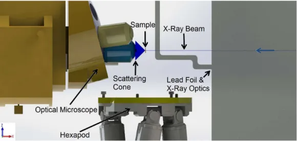
The working space of ID13 can be regarded as the main constraint for the design of the HSX-AFM. There are several parameters detailed by the ID13 scientists indicated in the schematics that can be seen in Figure 2.1. They can be summarized as:
• the sample holder : the sample is positioned in the X-Ray beam by the H-810 Miniature Hexapod from Physik Instrumente (PI) (which datasheet can be found in AnnexA). This instrument is also capable of rotating or tilting it for certain experiments. The maximum supported weight of must not exceed 5 kg. It has a range of movement of ±20 × ±20 × ±6.5 mm3 and has maximum stability with full distension along its vertical axis. Thus, the height from the base of the AFM to the sample needs to be minimized. The hexapod has a base with 100 mm diameter.
• the upstream shielding: to prevent retro-diffraction and isolate the mea-surement from background noise, a lead foil with a pinhole is placed between the last optical focusing element and the sample. It is made to accomodate the different elements of the beamline. A rough sketch can be found in Figure 2.1. The main constrain is the working dis-tance, from the pinhole to the sample along the beam, of dup
x = 10 mm. This and the other dimensions of the foil are target specifications with some freedom allowed, within certain tolerances. After the construction of the AFM, and after an upgrade of the focusing instrumentation of ID13, a special lead foil will be custom-made to fit perfectly with both instruments, assuring optimal shielding and steady AFM performance at the same time.
• the alignment apparatus: an optical microscope is used to pre-align the sample and the nanosized X-Ray beam. When aligning, this micro-scope’s objective is placed downstream of the sample at the projected beam height. The objective and the positioning of the optical micro-scope are build so that its focal point coincides with the one of the X-Rays, and the alignment can be done optically. After the alignment, the microscope is retracted and several detectors are approached. The main constraint is the optical microscope, as it is placed at ddownx = 10.55 mm from the sample. The objective of the microscope has a radius of 12 mm. There are no constraints in the y direction.
• the scattering cone: In order to perform Wide Angle X-Ray Scattering (WAXS) experiments, which makes possible the investigation of sub-nanometer characteristics of the sample, one has to collect all of the
Figure 2.1: xz profile sketch of the experimental Setup of ID13. The main components that constrain the design of the AFM can be seen: the Optical Microscope is placed at ddownx from the sample, while the lead foil distances dup
x from it. The profile of the X-Ray Optics support can also be seen, as well as a representation of the cone which is to be left free in order to allow wide angle scattering measurements.
photons scattered through a large cone angle from the sample. The AFM should be designed leaving free a cone with half-angle of 45◦ downstream of the sample, allowing scattering along these angles. One of the very important applications of this kind of AFM is the possibil-ity of localizing the nanometric beam exactly, within a macroscopic sample. The cantilever can be used as a detector of electrons emitted under X-Ray illumination [30]. Also the very small and precise movements associated with the AFM operation seem to be a perfect opportunity to include some of the optics of X-Ray instrumentation in the AFM structure and very close to the sample. For this reason, one of the important requests of ID13 was the in-clusion of some on-board optics in the structure of the AFM. Namely, order separating apertures (OSAs). These are simply pinholes, with diameter of some hundreds of nanometers, and their placement permits the user to select the energy of the incident beam in an automatic way, and without much cost in time and redundant instrumentation. If made properly, the inclusion of this kind of apertures would be a key aspect of the instrument. It would con-figure one of the first instances where X-Ray optics could be placed so close to the sample and with such an extremely good resolution in its positioning. If provided, these requests should make the HSX-AFM an instrument
capable of intervening in different experiments using X-Rays. Besides using the radiation as a simple exciting pump of the experiment, the design will also make possible X-Ray absorption spectroscopy experiments (for instance measuring the total electron yield) and also X-Ray diffraction experiments (like coherent diffraction).
The above requests alone make it clear that the construction of a sim-ple AFM to be integrated on a beamline is complicated, without severely compromising some of the performance associated with the instrument it-self. However, the gains in operation should well exceed these costs. It also demonstrates the novel character of the work done: the extremely hard environment for the placing of the AFM is perhaps the main reason this instrument was successfully built by an extremely limited number of groups in the scientific community, and going from a micro-focus to a nano-focus beamline makes all the spatial requirements even harder to be met.
2.2
What does it mean to go high speed?
This section presents a review of the main aspects necessary to be addressed in the construction of the HS-AFM, compiled from the work of the main authors that led the development of this technique [1,48, 2].
There are different measurement modes in AFM. However, all of the high speed AFMs use amplitude modulation mode as the main work mode of the instrument. Contact mode is not well suited for the study of biological matter, due to the fact that damaging high friction forces intrinsic to this measurement mode are incompatible with soft samples. Meanwhile, despite recent advancements in using the frequency modulation mode for imaging biologic matter in liquids [50, 51], FM-AFM seems to be only suitable for relatively flat samples. AM-AFM provides low invasiveness and can image rough samples routinely [24]. This mode was then chosen to guide the con-struction of the HSX-AFM.
Considering a driven cantilever with elastic constant, k, damping ratio, γ, and mass, m, its natural oscillation frequency is ω0 =
q
k/m and qual-ity factor Q = ω0m/γ. The quality factor of an oscillator is related to its relaxation time by τc = 2Q/ω0. An amplitude setpoint is defined, which defines a certain tip-sample average interaction. When scanned over a region of the sample with a different height, or a different material, the interaction changes. The response of the cantilever to a step-like force happens after a response time given by τc. The change in the resonant curve of the oscil-lator is measured by a change in the oscillation amplitude of the cantilever detected via a lock-in amplifier. This instrument has a measuring time con-stant τlock which determines the time it integrates the oscillation amplitude. The output of the lock-in is compared with the reference signal and a PID controller outputs a signal after a time τpid. This signal is fed back to the controller of the sample movement, changing the distance between the tip and the sample. This mechanism takes some time τz that depends on the controller, but also on the mechanical assembly of the whole AFM. Finally, the sample is displaced laterally so the measurement takes place in another point. A schematic diagram can be observed in Figure2.2.
The maximum imaging speed will depend, not only on the performance of each element mentioned above, but also on the image characteristics (how many points we have to measure) and the sample itself, that may be more or less difficult to measure. We can define the frequency of the loop, floop = (τc + τlock + τpid + τz + ...)−1, and spatial frequency of the corrugation of the sample νsample and the line velocity in an image, Vline. To perform an image the feedback loop needs to be able to compensate every change in
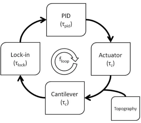
![Figure 2.4: High speed scanner used in Hansma’s HS-AFM, taken from [2]](https://thumb-eu.123doks.com/thumbv2/123dok_br/19186425.947775/48.892.189.765.192.434/figure-high-speed-scanner-used-hansma-afm-taken.webp)