Photostimulable X-Ray Storage Phosphors:
a Review of Present Understanding
Heinzvon Seggern
Darmstadt University of Technology Materials Science Division Department for Electronic Materials
Petersenstrae 23
D-64287 Darmstadt, Germany
Received 30 March, 1998
Photostimulable x-ray storage phosphors in form of image plates are a promising alternative to conventional two-dimensional x-ray detectors. By absorption of ionizing radiation, electrons and holes are generated and captured locally to form a dose proportional latent image. The stored information is read out by scanning with a focussed HeNe laser. This leads to a local excitation of the trapped electrons which subsequently recombine with the trapped holes causing the emission of light. The information is then recorded by means of a photomultiplier, digitized by an A/D converter and displayed with the aid of a computer. The present state of the eld of storage phosphors is reviewed in the following areas: the image principle, today's understanding of the nature of the storage centers, their physical generation, and the optically stimulated charge transfer paths. In addition, improvements and applications of these phosphors will be discussed for existing and future commercial devices.
I Introduction
Since its invention by C.W. Rontgen a little more than 100 years ago a vast number of dierent detection meth-ods for x-rays and generally ionizing radiation have been realized for application in medicine, physics, biol-ogy and materials science. In 1932 Professor Bernhard Gross wrote his rst article on ionizing radiation [1] about the pressure dependence of ionization of cosmic rays which nally led to the well known Gross trans-formation [2]. The ionizing radiation and its impact on matter has since then accompanied Bernard Gross through his still ongoing scientic life. In 1941 B. Gross published an article on the theory of ionization cham-bers [3] followed in 1948 by an article on a new type of Geiger-Mueller counter [4], followed again in 1960 to 1961 by a series of articles on Compton dosimeters [5-9]. This work was also granted a US-patent with the title \Method and apparatus for measuring the dosage of x-rays and gamma x-rays" [10]. Thereafter Gross became interested in the phenomenon of radiation induced con-ductivity in dielectrics which resulted in a series of pa-pers from 1964 about gammainduced currents in Teon [11] to 1989 about time-resolved x-ray induced
conduc-tivity in PET[12]. Today Gross is interested and ac-tively participates in work about secondary emission induced by low energy electron-beam irradiation which results in a very interesting contribution to the present issue of this journal [13].
The work presented below on storage phosphors as two dimensional radiation detectors contains the ideas and inspirations I experienced in my exciting time of collaboration with Bernhard Gross [14-18]. The radia-tion induced generaradia-tion of charge carriers and their sub-sequent storage in radiation induced defects is a com-mon language which connects the work of Prof. Gross with the storage phosphors for image plates.
determi-nation of the lateral intensity distribution, the object-penetrating radiation is recorded either in an x-ray lm, a lm/screen system or a wire chamber.
The most widely known technique is the x-ray lm. In medicine the lm/screen system is used solely due to its improved sensitivity compared to the x-ray lm [19,20,21]. Due to its relatively small thickness the x-ray lm exhibits a high spatial resolution, but its sen-sitivity is low. Its dynamic range is restricted because the lm structure contains sensitive Ag-halide grains of about one micrometer in size. Once such a particle has absorbed an x-ray quantum it will turn black dur-ing processdur-ing and no further absorption generates a measurable dierence. Therefore the total dose such a lm can record is restricted to the total number of Ag-halide grains. The range of useful ux is 2 to 3 orders of magnitude in x-ray dose to be registered.
In the lm/screen system, which is utilized mainly in medical diagnostics the low sensitivity of the x-ray lm is compensated by using a sandwich structure of a scintillating phosphor screen in combination with a photographic lm. In this case the radiation is strongly absorbed by the phosphor screen (intensifying screen) and converted with up to 20% energy eciency into visible light. This light is then absorbed by the pho-tographic lm which is the actual storage medium. In this way one gains the necessary sensitivity required for medical application, but one looses the high spatial res-olution of the original x-ray lm due to light scattering processes in the phosphor lm.
Theimage plate was introduced in 1983 as a new x-ray detector system [22]. The image plate was built in analogy to the intensifying screen and consists of a polymeric support lm covered by a layer of an or-ganic binder in which the functional phosphor grains are imbedded. Contrary to the intensifying screens, the principle of these image plates is not the radiation in-duced generation of spontaneous luminescence but the radiation induced photostimulable luminescence (PSL). In this case the radiation generated electrons and holes are captured in electron and hole traps in the imme-diate surrounding of their generation. Proportional to the density of these trapped carriers the image plate contains a latent image of the x-ray radiation dose. The information readout occurs by local optical excita-tion (photostimulaexcita-tion) in which the trapped electrons are liberated. These electrons then radiatively recom-bine with trapped holes under the emission of light.
The intensity of this emitted light is proportional to the density of trapped electron/hole pairs and thereby to the locally absorbed x-ray dose. Commercially applied storage media are the alkaline-earth halides BaF(Brx,I1,x):Eu
2+ with an added fraction (1-x) of iodine ions and the alkaline-halide RbBr:Tl+. Further potential candidates with excellent storage and readout properties are Ba2B5O9Br:Eu
2+, Ba
5GeO4Br6:Eu 2+ [23], Y2SiO5:Ce
3+, and Y
2SiO5:Ce
3+, Sm3+[24]. After a short introduction to the principle of image generation and readout with x-ray storage phosphors, the physical mechanismsof x-ray storage phosphors will be discussed. Of interest are the nature of the electron and hole traps, the generation of these traps during ir-radiation, and the mechanism of information readout by means of photostimulated luminescence. Further, developments show ways to improve the parameters of the standard storage phosphors such as shorter read-out time, a higher sensitivity and a better spatial reso-lution. At the end, an overview of existing and future applications of these interesting materials will be given.
II Imaging with image plates
The process of imaging with image plates consists of three parts
1. the x-ray exposure,
2. the information readout, and
Figure 1. Schematics of the imaging process utilizing image plates.
Image plates have the following advantages over other techniques:
dynamic range larger than 5 orders of magnitude in x-ray dose,
lower limit of useful dose compared to the x-ray lm,
reusability,
no wet chemical processing,
images are available in digital form,
image processing and pattern recognition possible, and
simple data storage on optical or digital media Disadvantages of image plates compared to the con-ventional x-ray lm are a poorer spatial resolution due to light scattering at the storage phosphor grains during the readout process.
III Physical mechanism for
BaFBr:Eu
2+storage
phos-phors
III.1Physicalnatureof electronand hole storage centers
X-ray storage materials contain at least two dier-ent storage cdier-enters: one for electrons which capture the x-ray-generated electrons and release them by photo-stimulation, and hole storage centers, called activators, which capture the x-ray-generated holes. In addition, these hole storage centers have to be able to capture an optically liberated electron and release the available energy to a luminescence center.
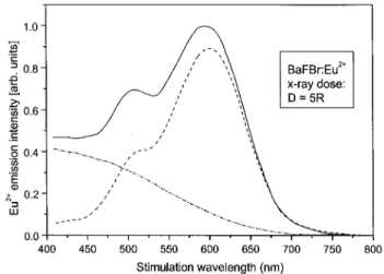
Figure 2. PSL spectrum of Eu2+ emission of a sample
which was x-ray irradiated at room temperature (solid line); the dashed line resembles the stimulation spectrum of the F(Br,) center obtained by the dierence spectra after
It is known that in halide crystals, F-centers (Far-bzentren) are generated by x-ray irradiation [25]. These centers are anion vacancies occupied by electrons. They are optically active displaying an oscillator strength close to one. In BaFBr crystals two types of F-centers are known, one based on a uorine-anion va-cancy and the other based on a bromine-anion vava-cancy [26]. Both types of centers are generated, however, only the bromine based centers act as occupied storage cen-ters contributing signicantly to the photostimulation process [27]. For the identication of the F- center the so called photostimulation spectrum is used. This spec-trum was obtained by tuning the excitation wavelength from 400 to 800nm and detecting the intensity of the Eu2+emission band at 390nm. The obtained spectrum resembles the spectral excitability of the PSL process and agrees in its shape to the absorption spectrum of the F-center. Such an agreement was veried explic-itly for the storage phosphor RbBr:Tl+ [28,29,30]. A band model for this photostimulation process is shown in Fig. 4 and discussed in more detail below. A typical PSL spectrum of BaFBr:Eu2+ is displayed in Fig. 2 as solid line. To separate the relevant F-center for the practically important excitation with a HeNe-laser at 632.8nm the sample was rst bleached at 625nm and subsequently a second PSL spectrum was recorded (see dash-dotted line in Fig. 2). The dierence of these two spectra is plotted as the dashed line and it was shown that this stimulation bands are typical for a bromine based F-center (F(Br,)-center) in BaFBr [27].
Figure 3. Comparison of Eu2+ emission spectra in
BaFBr:Eu2+ for x-ray, PL- (310nm) and PSL-(590nm)
ex-citation.
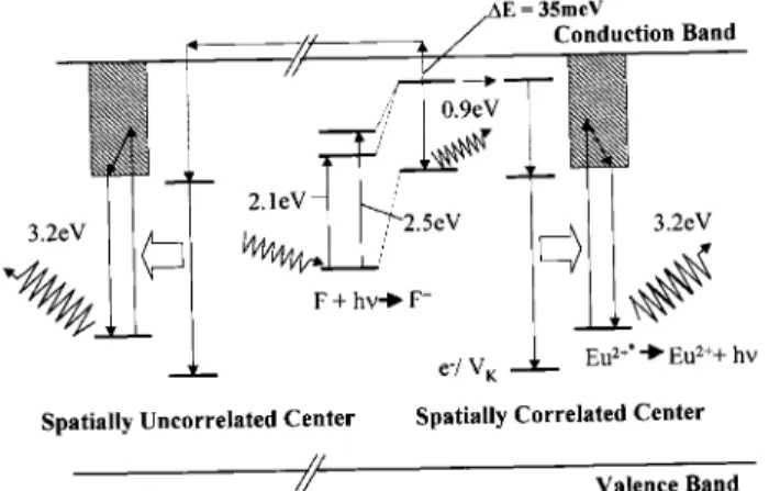
The electronic levels of the F(Br,)-center are
dis-played in Fig. 4. The center has two stimulation bands at 2.1eV and 2.5 eV, respectively. The excitation cor-responds to an optical dipole allowed transition from a 1s to a 2p state. From the physics of color centers it is known that the excited state, once occupied, un-dergoes a lattice relaxation within picoseconds due to the dierent charge distribution of the ground and the excited state. In Fig. 4 this is indicated by the dotted lines. The electronic energy of the relaxed excited state (RES) is found close to the conduction band so that the electron at low temperatures is still bound. For a release from the F-center a thermal energy of 35meV [27] has to be available which is comparable to the al-kali halides [30]. If this thermal energy is not supplied to the electron it will fall back into the F-center ground state via the non- relaxed ground state under the emis-sion of infrared light.
Figure 4. Bandmodel of the PSL process in BaFBr:Eu2+. The hole storage center will now be addressed. In all investigated materials the photostimulated lumines-cence originates from the characteristic emission of the activator. In the case of BaFBr:Eu2+ this corresponds to the Eu2+ emission [31] which is explained by a phonon broadened 4f65d
!4f
crystal [35]. This coincidence indicates the strong pos-sibility of a resonant energy transfer between a bound exciton at the Eu2+ site and the Eu2+ ion. The re-sulting model for the emission is then as follows: Eu2+ captures a hole, in the present case aV
K
, or H-center, upon irradiation. After photostimulation and libera-tion of the F-center electron this electron is captured by the trapped hole forming a bound exciton. When deexciting, the exciton transfers its energy resonantly to the Europium ion. The Eu2+ion will become excited and subsequently decays under the emission of its char-acteristic luminescence at 390nm (3.2eV). The scheme is also displayed in Fig. 4.
III.2 Charge transport during PSL In this section the question concerning the mecha-nisms of charge transport is addressed. In this context the relaxed excited state of the F-center plays a ma-jor role [27,36,37]. After photoexcitation the electron reaches the RES from where it can follow three dierent paths:
1) it escapes into the conduction band by accepting a thermal energy of 35meV from the lattice, 2) it tunnels to a neighboring hole center, or 3) it deexcites into the F-center ground state under
the emission of an infrared photon (0.9eV). Which one of the competing processes occurs de-pends on the spatial arrangement of the electron and hole storage centers, the temperature and the intrinsic lifetime of the electrons in the RES. The relative dis-tance of the storage centers determines the probability of the tunneling and the temperature determines the escape of the electron into the conduction band.
Before we continue two expressions will be intro-duced: the spatially correlated and the spatially uncor-related center. A spatially coruncor-related center is dened as one where the transfer occurs by tunneling and the uncorrelated center is one where this is not the case. The denition is meaningful since for tunneling to oc-cur, very small spatial distances between the involved electronic centers are required. In contrast to the un-correlated centers, which do not contribute to the PSL, as soon as the thermal energy to escape into the con-duction band is lacking within the lifetime of the RES
the correlated centers continue to allow PSL to occur even to the lowest temperatures.
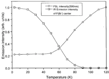
Under the assumption of these processes it was pos-sible to classify the PSL centers [27]. By employing the temperature dependence of the escape of the RES elec-tron to the conduction band all uncorrelated centers can be deactivated. In Fig. 5 the temperature dependence of the PSL intensity is displayed. In the corresponding experiment the sample was irradiated at room temper-ature and then cooled to the indicated tempertemper-atures. On the way down the information content was probed by a PSL experiment performed at very low stimula-tion light intensities. So no loss of PSL centers due to the experimental conditions were found. Therefore the observed step in Fig. 5 is solely due to the freezing-in of electrons in uncorrelated centers and not due to loss of the total number of centers. To further verify this result the sample was heated up again to temperatures as high as 120C and no dierence in the intensity amplitudes compared to the cooling-down phase was observed. The observation of an increasing infrared emission during this activation step in the cooling phase and a decreas-ing emission durdecreas-ing the heatdecreas-ing emphasizes the validity of this model. If an F-center without neighboring hole center is photo-excited and the RES electron cannot escape by thermal activation into the conduction band it can only relax into the F-center ground state under emission of infrared light.
Figure 5. Temperature dependence of the PSL and IR emis-sion intensities of a BaFBr:Eu2+ single crystal after x-ray
exposure at room temperature (x-ray dose: 5R; Vpp:70kV;
stimulation wavelength: = 590nm).
the activation step (>120K) resembles the ratio of spa-tially uncorrelated to correlated centers. In the dis-played example of a BaFBr:Eu2+ crystal the ratio is 20%. This ratio is found to strongly depend on the preparation. Examples between 10% [32] and 85% [37] were reported. The resulting transport processes are included in Fig. 4. The existence of correlated cen-ters was veried by Koschnik et al. [38] using opti-cally detected EPR-measurements which suggested a correlation to O, centers also observed in the material [39]. The existence of such correlated centers was al-ready predicted by theoretical interpretations of exper-imentally observed PSL decay curves [36,40]. Similar investigations concerning the readout mechanism were performed on RbBr:Tl+, and RbI:Tl+, and similar pro-cesses were observed [28,41].
III.3 X-ray formation of PSL storage
cen-ters
The previously presented results concern the read-out process and the nature of the electron and hole stor-age centers. Physically interesting, however, is the pro-cess by which these centers are generated. Two models are discussed. Both models start from dierent initial condition. In the rst model it is assumed that the ma-terial contains a sucient number of positively charged anion vacancies (F+-centers) which become occupied by x-ray generated electrons to form F- centers. The simul-taneously generated holes, in this case the well known V
K-centers, are trapped by the Eu
2+centers to form re-combination centers. The simplied reaction equations are
h x,ray
!e ,+
V K
;
e ,+
F +
!F (1) ;
V K+
Eu 2+
!(V K
=Eu 2+)
,complex:
The second model claims the absence of anion va-cancies and assumes that the complete center is gen-erated by the x-ray irradiation. This model was origi-nally proposed by Itoh [42] for alkaline halides and was suggested by von Seggern to explain the processes in storage phosphors. According to Itoh the absorbed x-ray energy forms excitons. Upon its decay the released energy displaces a Br-atom from its regular lattice site
leaving the electron behind. The Br-atom then com-bines with a neighboring Br,-ion to generate the well known H-center, a Br,
2-center. The electron left behind is trapped in the bromine vacancy and establishes the F(Br,)-center. The H- center then diuses through the lattice and gets trapped at an Eu2+-site generating the Eu2+/hole complex acting as a recombination center. The adequate reaction equations are
l l lh x,ray
! (e ,
=h)exciton; (e
,
=h),exciton ! F,Hpair; F,Hpair ! F+ (H =Eu
2+)
,complex: (2) The model by von Seggern is supported by measure-ments at the HASYLAB (DESY) in Hamburg which showed a drastically increased production of PSL-centers when the material is excited within the exciton bands [43,44,45] (see Fig. 6). Since the excitonic state is a major part of the Itoh model it has to be considered as part of the formation process. The model is further supported by the unsuccessful experiments to obtain a larger F+-center concentration by thermal quenching the material. Presently there is no clear proof for one or the other model. Due to the experimental evidence it seems, however, that the Itoh model is more appro-priate.
Figure 6. Comparison of reectivity (a), spontaneous lumi-nescence (b), and formation of photostimulable centers (c) in a BaFBr:Eu2+-single crystal [23]. The relevant exciton
IV Improved performance by
new and modied storage
phosphors
Storage phosphor systems are commercially available but are mainly directed towards medical application. Since in this application the necessary x-ray dose is of major concern one has to compromise between the de-sired spatial resolution and the sensitivity of the image plate. In practice one accepts a reduced resolution in favor of a higher sensitivity. In the eld of materials science these constraints are often relaxed.
Improvements can be separated in two types: (a) improvements of physical parameters such as stimula-tion wavelength and readout time and (b) improvement of image plate properties for PSL sensitivity and spatial resolution.
IV.1 Photostimulation in the
near-infrared
As discussed in the previous chapters, BaFBr:Eu2+ is stimulated at 590nm. For the HeNe-laser this wave-length is not optimal as can be seen in Fig. 2. It would therefore be desirable to shift the stimulation spectra more towards the red or to the near infrared since very powerful and small solid state lasers are available.
It is important to understand the relation between the stimulation wavelength and the properties of the electron trap. From the alkali halides such a relation-ship is known as the Mollwo relation [46]. It describes the dependence of the absorption energy and the physi-cal size of the anion vacancy. This relation has its origin in the simple picture of an electron in a potential well in which the relation can be formulated as
E = E2p ,E
1s= 3 2
~ 2
8ma2 ; (3)
where E1s and E2p represent the energy in the ground state and the excited state, respectively. m is the ef-fective electron mass and a the width of the potential well. One realizes that an enlargement of the poten-tial well results in a reduction of the excitation energy and a shift of the exciting wavelength towards longer wavelength.
That this relationship qualitativelydescribes the red shift can be seen from storage phosphors made of al-kali halides such as RbBr:Tl+ and RbI:Tl+. In these
materials the PSL stimulation spectrum follows the ab-sorption spectra of the F-centers which is reported at 700nm [28,29,47] for RbBr:Tl+ and at 780nm [41] for RbI:Tl+. The latter material is very promising with respect to its physical properties, however, a thermal instability of information storage related to an extreme sensitivity to humidity makes its application dicult.
The inuence of material modication on the photostimulation spectrum was shown in an arti-cle by Winnacker [48] in which he presented results on BaFBr:Ce3+ and BaF(Br,I):Ce3+. An addition of 16 mol-% of BaI2 to the regular preparation of BaFBr:Eu2+ resulted in a large red shift of the stimu-lation spectrum (see Fig.7). The shift was explained by the implantation of the larger iodine ion in the bromine lattice which enlarges the average lattice spacing and therefore widens the F(Br,)-centers. As indicated by the two laser lines, the modied storage phosphor can already be eciently used in combination with a 670nm GaAlAs solid state laser.
Figure 7. Photostimulation spectra of BaFBr:Ce3+ and
BaF(Br0:84I0:16):Ce 3+[48].
A red shift in the photostimulation spectrum was also reported by Meyerink [49] and by Dietze et al. [50] who investigated nonstoichiometric crystals of (Ba,Sr)F1+xBr1,x:Eu
2+ and (Ba
by Strontium ions. Dietze et al. report that F A(Br
,, Sr2+) centers are generated which exhibit an absorption band at lower energies and could explain the observed red shift for these materials.
IV.2 Faster readout times
For the practical use of the image plate system it is important to read out the imaged information in rela-tively short times. Today's systems are capable of cycle times of about 1 min [34] for the readout time and the erasure time. The readout time and the erasure time are inuenced by two factors:
the optical cross section of the photoexcited F-center and
the lifetime of the photostimulated luminescence. The rst process is determined by the oscillator strength of the F-center and the second by the life-time of the rst excited state of the Eu2+-ion [37]. The rst limitation is a practical limit determined by the available laser power. The second one is a fundamental limitation which limits the possible readout speed. If one scans too fast, the initially excited pixel will still emit light while the next pixel is excited leading to a degraded resolution.
IV.2.1 Optical cross section of storage
phosphors
The practical readout time is limited by the optical cross section
0 and the laser intensity I
0. The readout time is related to these according
= ( 0 I 0) ,1 ; (4)
where describes the time which is necessary to read out the information to the e,1-th value. It determines the average duration a laser has to stay on each pixel to obtain a acceptable image quality:
N=N 0
e ,t=
)t=ln N
0 N
; (5)
whereN
0is the total number of generated PSL-centers and N the number of erased centers due to photostimu-lation. For an optimal readout the optical cross section should be at the maxium of the excitation spectrum,
and it should have a high absolute value. Since only HeNe lasers or solid state lasers are presently applied in commercial scanners, their low intensity causes the time constant in Eq.(5) to be a problem.
Optical cross sections of various storage phosphors are displayed in Table I and compared to theoretical data [30,36] The experimentally determined values are by a factor of 3 to 5 larger than the theoretical data. One could speculate that this dierence is caused by the local light intensity which strongly depends on the grain size and there with the scattering of the incident laser light. In this context the relatively small value of the cross section in BaFBr reported by DeLeeuw et al. [40] could also be related to a dierent grain size distribution.
The impact of the optical cross section and the laser intensity can be shown when calculating the time nec-essary to record a complete image. For a medical ex-posure of the thorax one uses lm sizes of 4040 cm
2 digitized in a pixel size of 100100, m
2. For a nor-mal exposure one has to read out about 20% of the generated PSL-centers to obtain a good image quality. Applying a 40mW HeNe laser (as is done in commercial scanners) which impinges on a single pixel one obtains a laser intensity of 1:2510
21photons/cm2. With these values Eqs.(4) and (5) result in a readout time for a single pixel of t = 2:54:10
,7s. For a complete image one would then need 4.1s. Using a solid state laser (e.g. a GaAlAs laser emitting at 780nm) and the matching x-ray storage phosphor like RbBr:Tl+ one could easily reduce the readout time by a factor of more than ten.
IV.2.2 Lifetime reduction of storage
phosphors
In commercially available image plate systems it is the lifetime
L of the photostimulated luminescence which limits the performance. This luminescence life-time was measured at room temperature to be
In this chapter storage phosphors will be introduced which exhibit shorter PSL lifetimes. The lifetime lim-iting process must be investigated. Possible factors are the optical excitability of the electron trap, the thermal activation step, the trap-modulated charge transport in the conduction band, or the time delay induced by the recombination center itself. It was found that the rate limiting factor is introduced by the lifetime of the dopant in all investigated substances [29,37,41]. In case of BaFBr:Eu2+ it was shown that the PSL lifetime and the photoluminescence lifetime do agree within the ap-plied temperature range from room temperature down to LHe temperatures. Since in the photoluminescence experiment only the dopant is excited, this agreement indicates no other time limiting processes in the PSL.
Figure 8. Comparison of the experimental PSL lifetime of BaFBr:Eu2+, BaFBr:Ce3+ and RbBr:Tl+ after pulse
exci-tation (10ns) at 590nm [48].
In order to decrease the PSL lifetime a dopant with a shorter inherent lifetime has to be used. The only available candidate is the Ce3+-ion which is known to exhibit a lifetime shorter than 100ns. A comparison of the PSL lifetimes of both the Eu2+and the Ce3+doped BaFBr is displayed in Fig. 8 [48]. The resulting lifetime
was measured to be 95ns [48]. For the image readout time this resembles an improvement by a factor of 8 reducing the above discussed 36s for a complete image readout to 4.5s. This value matches the practical limits for the present system. To fully utilize the existing laser power of solid state lasers at 670nm, the PSL lifetime has to be decreased by another factor of at least ten (see Eqs. 4 and 5). In this context it is interesting to mention that dierent dopants in RbI result in dierent lifetimes. A collection of all measured values in RbI is shown in Table II. The lifetimes extend from 350ns for a Thallium doped material to 3s for an Indium doped one [41].
V PSL-eciency and
informa-tion stability
Since the PSL eciency is one of the major performance factors of a detector system the present understanding of parameters determining this eciency will be dis-cussed. The PSL eciency is inuenced by:
absorption of the primary radiation, conversion to PSL centers,
eciency of readout,
structure of the image plate (scattering of stimu-lating light), and
collection of PSL photons.
V.1 Non photostimulated centers in
BaFBr:Eu
2+In alkaline halides F-centers and higher agglomer-ates are generated by ionizing radiation [25,30]. In stor-age phosphors a variety of centers could be detected by their inherent infrared emission at low tempera-tures. Such an emission (0.9eV) is included in the term scheme of a F(Br,)-center in Fig. 4. After determina-tion of the dierent infrared emission bands, the non-photostimulated centers can be identied by their char-acteristic excitation spectrum. Since excitation spectra of F- centers and of their aggregates are known in the case of the alkaline-halides, this knowledge can easily be transfered to the alkaline-earth halide storage
phos-phors.
V.2 Formation energy of centers in
BaFBr:Eu
2+The above results were used to estimate the energy eciency of a BaFBr:Eu2+-crystal [51]. The energy necessary to generate a PSL center was determined fol-lowing the ux diagram shown in Fig. 9. Taking into account the energy spectrum of the x-ray tube and the absorption and energy conversion coecients, the ab-sorbed energy was calculated. This energy was com-pared to the spontaneously emitted photons during x-ray irradiation which leads to a formation energy of 129 eV / spontaneously emitted photon. Then a compari-son was performed between the number of PSL photons and spontaneously emitted photons which accounts to a ratio of 1.53. Taking this value and the concentration of non photostimulable centers (see Table IV) into ac-count one obtains a value of 21 eV / x-ray generated center. It is assumed that the formation energy of each center is the same. In addition, it is assumed that the oscillator strength of the dierent centers is the same. This is a good assumption since all centers are gener-ated by the Itoh process or by an ionization process. In both cases every center creation process starts with an elementary process of generating an exciton or equiv-alently an highly excited electron. The assumption of the same value for the oscillator strength for all centers is also acceptable [30].
Figure 9. Flux diagram of the energy balance of the gener-ation of a PSL center in BaFBr:Eu2+.
The formation energy of 21 eV per center is very low with respect to the gap energy of 8.3 eV in BaFBr:Eu2+. The value for generating an electron hole pair in a semi-conductor or insulator amounts to about 3 times the bandgap. Under the above assumptions the totally ab-sorbed energy is eciently used to generate defect
cen-ters. For a further improvement of BaFBr:Eu2+ the only way is to reduce the number of non photostimu-lated centers or the number of spontaneously emitted photons. The number of 16% of photostimulated cen-ters allows further improvement.
VI Performance parameters
Image quality plays a major role in the performance of image plate systems. Image quality is determined by the following factors:
spatial resolution,
image noise or homogeneity, and PSL sensitivity.
Figure 10. Schematics of propagation of photostimulation and emitted PSL light in an image plate.
These image parameters are investigated in a num-ber of publications [52-58] dealing with commercially available image plates. A study on ceramic storage phosphors [59], found performance similar to the clas-sical plates. Recently, theoretical models estimated the inuence of light propagation on the image plate perfor-mance [60-62]. One model was based on light propaga-tion by a diusion model [60,61], and the other modeled the light propagation by a Monte Carlo technique [62]. Both experiments were able to qualitatively describe the image parameters.
VII Applications
In Fig. 11 an overview of today's and future elds of application are shown [63,64]. Commercial systems are available for medical diagnostics [22,65,66], for gen-eral crystallography [67-70], for protein crystallography [71,72] and for auto-radiography [73]. New applications have been suggested in the eld of data storage [74], electron microscopy [75], detection of soft x-rays [76], and in the eld of dosimetry [77].
Figure 11. Present and future applications of x-ray storage phosphors.
Close to commercial application is the utilization of image plates as thermal neutron detectors. This method is interesting since it oers complementary in-formation compared to the x-ray application. Since commercial image plates exhibit a too small absorp-tion for neutrons, they were initially combined with a gadolinium metal lm which strongly absorbs thermal neutrons [78]. The gadolinium is a neutron converter with a very large cross section of 49700 barns/atom. By an (n;)-reaction, energetic electrons are liberated with energies between 29 and 130 keV which then expose the image plate. This, however, leads to a drastically re-duced spatial resolution [78,79].
The problem was eliminated by introducing a uni-form mixture of Gd2O3powder of 2
VIII Outlook
X-ray storage phosphors have already reached a high level of performance with commercialapplications. One looks forward to future improvements and new applica-tions. The large number of non-photostimulated cen-ters, it seems, still can be improved with respect to sensitivity and spatial resolution.
Today's lms are tuned towards medical application which implies a compromise between spatial resolution and PSL sensitivity. For applications in materials sci-ence and quality control the requirements are dierent. In quality control the demand for a higher spatial res-olution is essential which means that the grain size of the phosphor has to be reduced or new layer techniques have to be developed. For applications in materials sci-ence, such as diractometry the need for more quanti-tative data is increasing.
Since today's image plates have a relatively large temporal loss of information after exposure one has to search for mechanisms to stabilize the recorded infor-mation. This is especially important for applications which require a long term exposure. Scientically, the question of the nature of the hole traps is still under debate, as is the question of the generation mechanism of the PSL centers. New ideas are necessary to identify the possible radiation products during center formation such as the VK-centers and the H-centers.
References
1.. B. Gross, Zeitschrift fuer Physik78, 271 (1932). 2.. B. Gross, Zeitschrift fuer Physik83, 214 (1933).
3. B. Gross, An. Acad. Bras. Ci Symposium sobre raios cosmicos, 171 (1941).
4. B. Gross, An. Acad. Bras. Ci20, 4 (1948). 5. B. Gross, Metrology of radionuclides IAEA, 413
(1960).
6. B. Gross, P.V. Murphy, Nucleonics19, 86 (1961). 7. B. Gross, J. Radiation Research 14, 117 (1961). 8. B. Gross, P.V. Murphy, Selected Topics in
Radia-tion Dosimetry IAEA, 549 (1961).
9. B. Gross, An. Acad. Bras. Ci, Comunicac~ao40, 3 (1968).
10. B. Gross, US-Patent 3122640, (25.Feb.1964). 11. B. Gross, Nucleonic6, 20 (1964).
12. R. Gregorio Filho, B. Gross, J. Appl. Phys. 66, 5478 (1989).
13. B. Gross, C.A.F. Pintao, R Hessel, to be published in this issue.
14. B. Gross, J E. West, H. von Seggern, D.A. Berkley, J. Appl. Phys. 51, 4875 (1980).
15. B. Gross, H. von Seggern, D.A. Berkley, Conf. on Electrical Insulation and Dielectric Phenomenon, 206, (1982).
16. B. Gross, H. von Seggern, D.A. Berkley, Phys. Stat. Sol. 79, 607 (1983).
17. B. Gross, H. von Seggern, J.E. West, D.A. Berkley, Conf. on Electrical Insulation and Dielectric Phe-nomenon, IEEE, 227, (1984).
18. B. Gross, H. von Seggern, J.E. West, J Appl. Phys. 56, 2333 (1984).
20. D. Zweig, J. Zweig, Imaging Techn.10, 43 (1984). 21. P.C. Bunch, K E. Hu, R. van Metter, SPIE Vol.
626, Medicine XIV/PACS IV, 64 (1986).
22. M. Sonoda, M. Takano, J. Miyahara, H. Kato, Ra-diology148, 833 (1983).
23. A. Meijerink, G. Blasse, J. Phys. D: Appl. Phys. 24, 626 (1991).
24. A. Meijerink, W.J. Shipper, G. Blasse, H. Phys. D: Appl. Phys. 24, 997 (1991).
26. M. Yuste, L. Taurel, M. Rahmani, D. Lemyne, J. Phys. Chem. Solids37, 961 (1976).
27. M. Thoms, H. von Seggern, A. Winnacker, Phys Rev. B44, 997 (1991).
28. K. Amitani, A.Kano, H. Tsuchino, F. Shimida, SPIE Conf. and Exhibition: Electric Imaging, 26th Fall Symposium 1986, Printing of Paper Summaries, 180.
29. H. von Seggem, A. Meijerink, T. Voigt, A. Win-nacker, J. Appl. Phys. 66, 4418 (1989).
30. B. Fowler, inPhysicsofCokrurCenters,edited by W.B. Fowler (Academic Press, New York 1968). 31. K. Takahashi, K. Kohda, J. Miyahara, J.
Lumi-nescence 31&32, 266 (1984).
32. T. Hangleiter, F.K. Koshnick, J.-M. Spaeth, RH.D. Nuttal, R.S. Eachus, J. Phys. Condens. Matter 2, 6837 (1990).
33. F.K. Koshnick, J.-M. Spaeth, R.S. Eachus, W.G. Mc Dugle, R.H.D. Nuttal, Phys. Rev. Lett. 67, 3571 (1991).
34. M. Thoms, H. Burtzla, A. Kinne, H. von Seggem, R. Spengler, A. Winnacker, Materialis Science Fo-rum228-231,107 (1996).
35. H.H. Rueter, H. von Seggem, R. Reininger, V. Saile, to be published in J. Appl. Phys.
36. H. von Seggem, T. Voigt, W. Knuepfer, G. Lange, J. Appl. Phys. 64, 1405 (1988).
37. H. von Seggem, Cryst. Latt. Def. and Amorph. Mat. 18, 99 (1989).
38. F.K. Koshnick, J.-M. Spaeth, R.S. Eachus, J. Phys.: Condens. Matter 4, 8019 (1992).
39. F.K. Koshnick, J.-M. Spaeth, R.S. Eachus, J. Phys.: Condens. Matter 4, 3015 (1992).
40. D.M. DeLeeuw, T. Kovats, S.P. Herko, J. Elec-trochem. Soc. 134, 491 (1987).
41. M. Thoms, H. von Seggem, A. Winnacker, J. Appl. Phys. 76, 1800 (1994).
42. N. Itoh, Adv. Phys. 31, 491 (1982).
43. H.H. Rueter, H. von Seggem, R. Reininger, V. Saile, Phys. Rev. Lett. 65, 2438 (1990).
44. V.V. Mikhailin, Nuc. Instr. Meth. 261, 107 (1987).
45. E. Nicklaus, Phys. Stat. Sol. (A).53, 217 (1979). 46. E. Mollwo, Goett. Nachrichten 1931, 97 (1931). 47. K. Amitani, A. Kano, H. Tsuchino, F. Shimada,
SPE's Conf. And Exhib.: Electric imaging, 26th Fall Symposium, 1986, Printing of Paper Sum-maries 180.
48. A. Winnacker, Physica Medica, Vol. IX, N.2-3, 95, April-September 1993.
49. A. Meijerink, Materials Chemistry and Physics 44, 170 (1996).
50. C. Dietze, Th. Hangleiter, P. Willems, P.J.R.
Leblans, L. Struye, J.-M. Spaeth, J. Appl. Phys. 80, 1074 (1996).
51. M. Thoms, H. von Seggem, J. Appl. Phys. 75, 4658 (1994).
52. A.R. Lubinsky, J.F. Owen, D.M. Kom, SPIE Vol. 626, Medicine XIV/PACSIV, 120 (1986).
53. A.R. Lubinsky, B.R. Whiting, J.F. Owen, SPIE Vol. 767, Medical imaging, 167 (1987).
54. K. Klingenbeck, B. Conrad, Siemens Forschungs-und Entwicklungsbericht16, 192 (1987).
55. W. Hillen, U. Schiebel, T. Zaengel, Med. Phys. 14, 744 (1987).
56. M. Tecotzky, C. Andrew-Eurglunes, SPE Vol. 914, Medical Imaging II, 143 (1988).
57. R.H. Templer, N.A. Warrender, J.M. Seddon, J.M. Davis, Nuc. Instr. Meth. A310, 232 (1991). 58. R.H. Templer, Nuc. Instr. Meth. A300, 357
(1991).
59. BMBF-Final Report \Development of ceramic x-ray storage phosphors" Proj. No. 03M2707 (1993).
60. M. Thoms, Applied Optics35, 3702 (1996). 61. M. Thoms, H. von Seggern, J. Appl. Phys. 81,
5887 (1997).
62. R. Fassbender, A. Winnacker, to be published. 63. H. von Seggern, Physikalische Blatter 48, 719
(1992).
64. H. von Seggern, Nuc.Instr.Meth.: Phys. Research. A322, 467 (1992).
65. \Konica Direct Digitizer KD-1000", a product of Konica working with RbBr:Tl+.
66. G. Witte, B. Schwemmer, E. Buecheler, Deutsches Aerzteblatt86, A-2539 (1989).
67. Y. Amemiya, S. Kishimoto, T. Matsushita, Y. Satow, M. Ando, Rev. Sci. Instr.60, 1552 (1989). 68. B.R. Whiting, J.F. Owen, R.H. Rubin, Nuc. Instr.
Meth. A266, 628 (1988).
69. H. von Seggern, Materials Science Forum79-82, 383 (1991).
70. Announcement of a Guinier Diractometer by Hu-ber Diraktionstechnik GmbH, Germany.
71. J. Hendrix, Rev. Sci. Instr. 63, 641 (1992). 72. J. Miyahara, K. Takahaschi, Y. Amemiya, N.
Kamiya, Y. Satow, Nuc. Instr. Meth. A246, 572, (1986).
73. Y. Amemiya, J. Miyahara, Nature336, 89 (1988). 74. J. Lindmayer, Solid State Technol. 137, (Aug.
1988).
75. N. Mori, T. Oikawa, Y. Harada, J. Miyahara, J. Electron. Microsc. 39, 433 (1990).
76. P. Witt, Pure Appl. Opt. 2, 61 (1993).
Dosimetry55, 247 (1994).
78. Ch. Rausch, T. Buecherl, R. Gaehler, H. von Seg-gern, A. Winnacker, SPE Vol. 1737 Neutrons, X-Rays and Gamma X-Rays, 255 (1992).
79. C. Wilkinson, SPE Vol. 1737 Neutrons, X-Rays and Gamma Rays, 324 (1992).
80. T. Buecherl, Ch. Rausch, H. von Seggern, Nuc. Instr. Methods A333, 502 (1993).
81. H. von Seggern, K. Schwarzmichel, T. Buecherl,
Ch. Rausch, Materials Science Forum 166-169, 267 (1994).
82. M. Thoms, M.S. Lehmann, C. Wilkinson, Nucl. Instr. Meth. Phys. and Research A384, 457 (1997).
![Figure 6. Comparison of reectivity (a), spontaneous lumi- lumi-nescence (b), and formation of photostimulable centers (c) in a BaFBr:Eu 2+ -single crystal [23]](https://thumb-eu.123doks.com/thumbv2/123dok_br/18978595.456192/6.918.508.796.681.1047/figure-comparison-reectivity-spontaneous-nescence-formation-photostimulable-centers.webp)
![Figure 7. Photostimulation spectra of BaFBr:Ce 3+ and BaF(Br 0:84 I 0:16 ):Ce 3+ [48].](https://thumb-eu.123doks.com/thumbv2/123dok_br/18978595.456192/7.918.500.848.562.817/figure-photostimulation-spectra-bafbr-ce-baf-br-ce.webp)
![Figure 8. Comparison of the experimental PSL lifetime of BaFBr:Eu 2+ , BaFBr:Ce 3+ and RbBr:Tl + after pulse exci-tation (10ns) at 590nm [48].](https://thumb-eu.123doks.com/thumbv2/123dok_br/18978595.456192/9.918.140.824.136.255/figure-comparison-experimental-lifetime-bafbr-bafbr-rbbr-tation.webp)


