ABSTRACT: Under conditions of the inluence of space environment factors, the thin-walled load-carrying transformable-volume structures are subjected to volumetric deformation and long-time exposure to external loads, close to maximum permissible design values. The required functional properties of transformable-volume structures are ensured on the basis of applying surface engineering methods, whose effectiveness is dificult to conirm as there is no possibility to reproduce the space environment factors complex under the terrestrial conditions. The method for veriication of applied technologies regarding the modiication of surface properties was described. It was based on the comparison of inite-element and experimental-computational models of displacements in equivalent fragments of the transformable-volume structures surface. Qualitative and quantitative evaluation of methods is given, allowing changing the rigidity-strength characteristics of transformable-volume structures for space applications without alteration of their mass and compactness.
KEYWORDS: Transformable-volume structures, Surface engineering, Non-destructive testing, Electron shearography, Load-carrying shells, Foldable shells.
Functional Characteristics Improvement of
Metal Transformable-Volume Structures
for Space Applications
Leonid M. Lobanov1, Valentin S. Volkov1, Alexander V. Yakimkin1, Viktor V. Savitsky1
INTRODUCTION
Deployable structures refer to the actively developing ield of space technologies, which allow simplifying the delivery of useful freight to the near-Earth orbit. In the majority of cases the deployable or inlatable space structures represent shells made of elastic sot materials, capable of withstanding multiple non-fracturing bends. herefore, the main attention of developers of these types of structures is focused on the provision of shell rigidity and its stability ater deployment by using diferent methods of strengthening, which have limited efectiveness (Pellegrino 2015; Underwood et al. 2015; Schenk et al. 2014).
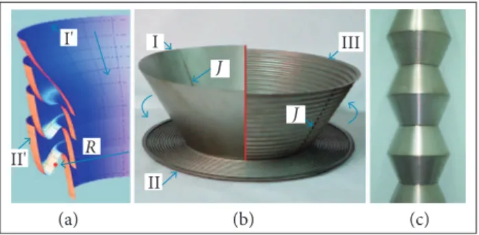
A separate class of deployable structures are transformable-volume structures (TVS) with a metal shell (Fig. 1c), in which the use of geometric regularities of surface bending allows realizing the volumetric deforming, comparable with the bends of sot materials (Paton et al. 2015). One of the applications of such structures is their use as a sliding bearing rod rigidly ixed at one of its ends on the outer surface of the base spacecrat (e.g. the International Space Station — ISS). In the working state ater unfolding the metal TVS has higher spatial rigidity compared with the initial metal shell before its transformation to a compact state. In creation of similar structures the main objects for research are the methods of surface engineering, whose application allows providing the required functional properties of the transformable shell with minimum weight and maximum compactness under condition of aggressive space environment factors (SEF) action. Finally, it is necessary to solve the problem of correctness of calculated evaluations at the stage of laboratory and check tests. his problem is predetermined by
1.National Academy of Sciences of Ukraine – The E. O. Paton Electric Welding Institute – Kiev – Ukraine.
Author for correspondence: Valentin S. Volkov | National Academy of Sciences of Ukraine – The E. O. Paton Electric Welding Institute | 11, Bozhenko str. | 03680 – Kiev – Ukraine | Email: [email protected]
the impossibility of reproduction of all SEF spectrums, under the Earth conditions, and also by complexity and high cost of experiments for their simulation.
2,000 Hz, linear and angular inertial loads. It is also subjected to cyclic temperature inluence in solar terminator transition with a maximum admissible temperature diference from −150 up to +125 °С. he decrease in a given range provides the decrease in temperature gradients in the shell structure at cyclic heating and, consequently, leads to the decrease in deformations, in which the maximum values are almost always regulated for deinite conditions of service and application of TVS. In addition, the working temperatures of optical surfaces also predetermine other parameters, whose range is limited by the requirements of structures for space applications — for example, the rate of precipitation of volatile condensing substances and duration of a possible contact of an operator in a space suit during the work beyond the ISS (for conical TVS it is more than 5s at temperatures from −43 up to +63 °С). he combination of the above-mentioned requirements allows selecting in most cases stainless steel as the optimum material for a TVS shell, providing also the lower deformability of structure under service conditions due to the value of Young’s modulus, which is 1.5/2.0 times higher than that of titanium and aluminium.
he use of a complex approach to the surface engineering allows providing the optimum combination of factors which, to a larger extent, determine the strength and stability of the structure under the SEF efect at the best mass-dimensional characteristics. he design coniguration of multisectional conical TVS, which is given by the authors as a main example, is defined by their definite functional application and can vary by changing the geometric sizes of separate sections and thickness of their structural material. On the other hand, the compactness, or coeicient of transformation KТ, is related to geometric parameters of conical sections of given thin-walled TVS with a stainless steel shell by the dependence:
I' I
II'
II
J J
R
III
Figure 1. Graphic representation of the mathematical model
for: (a) Fragment transformation of the initial conical shell (Iʹ) into a single corrugation (IIʹ); (b) The transformation stages of the metal TVS shell; (c) Design solution for multi-conical TVS. J represents the welded joints of the shells.
METHODOLOGY
he strength and spatial rigidities are referred to the main functional characteristics of TVS, subjected to improvement. hey guarantee the mechanical integrity of the transformable shell, its minimum deformability and absence of a local buckling at any combinations of external and operational loads, as well as stability, speed of unfolding and its sequence. The mentioned characteristics depend not only on a general geometric coniguration of TVS, properties and thickness of the structural material, type of joining stifening elements between separate sections, but also on local features of surface geometry (type of surface folding) and on others, irst of all, thermal optical properties of the surface.
Selection of design parameters and the task of improvement in the functional characteristics of TVS are reduced to the search for the best combination of strength and rigidity characteristics of the shell and its compactness at minimum possible weight. he thin metal shell of TVS should preserve the mechanical integrity and functional properties under the efect of mechanical loading factors, acting in the process of orbital injection (impact-pulsed loading and acoustic noise) and in the process of operation under space environment conditions. In particular, in case of rigid ixation at the external surface of the ISS, the structure can be subjected to the action of sinusoidal (harmonic) vibration in the range of frequencies from 5 up to 20 Hz and wide-band random vibration in the range of frequencies from 20 up to
where: n is the number of folds (circumferential corru-gations) in the shell transformed into a lat disc (Fig. 1b, II); S is the slant height of initial cone (Fig. 1b, I); α is the angle of conicity of initial cone; δ is the thickness of structural material of the TVS shell.
The tendency to maximum values of KT, attainable at δ → min, at unchanged preset design coniguration of TVS, requires the correction of lat disks manufacture technology and, inally, the decrease in radius of bending in apexes of
(a) (b) (c)
circumferential corrugations. he volume deforming of the initial steel shell with the formation of surface folds allows changing its space rigidity ater deployment (Fig. 1b, III) at δ = constant and at diferent variants of meridian proile (Fig. 1a). In our case, not only the operation of shape formation is achieved by plastic deformations of the steel shell, but also the required complex of properties of the structural material is attained.
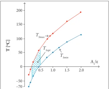
Further, the application of surface engineering methods applied to metal TVS is of current importance for changing their thermal optical properties. he temperature of TVS surface (TS), whose material has a high coeicient of thermal expansion, deines mainly its deformation mode. he value TS under other equal conditions is determined only by the AS/εratio, where AS is the coeicient of solar radiation absorption and ε is the emissivity coeicient of TVS optical surface. he possibility to inluence this ratio allows changing within wide ranges the structure deformability under conditions of the orbital light. Figure 2 illustrates the dependence of minimum (TSmin) and maximum (TSmax) calculated values of temperatures on the TVS surface of a conical type (material: steel AISI 321) on the AS/ε ratio in service of the structure in random working point of the ISS’s external surface. he selected zone (TSopt) limits the selected optimum range of temperatures (−43 to +63 °C), corresponding to the ratio AS/ε = 0.26/0.54.
of stability and strength analysis of a deinite structure and the estimation of optimum combination of methods for strengthening and for optical surfaces treatment, which allows deformability reduction. At this stage it is necessary to implement the efective methods of monitoring, which could conirm the correctness of calculations by using numerical methods and reduce as much as possible the cycle of complex and expensive on-land stand tests of the structure at the stage of manufacture. In creating a TVS (Fig. 1c) the veriication of a inite-element computational model of the structure has been implemented by the method of electronic shearography. At the same time, the efectiveness of the discussed methods below for surface property modiication was conirmed in the modelling of radiation heating under vacuum conditions on separate segments of the conical structure. For these segments the boundary conditions on the circular mating contours corresponding to a multi-sectional shell have been reproduced.
RESULTS AND DISCUSSION
ALTERATION IN SPATIAL RIGIDITY OF A TVS SHELL
he transformation of a circumferential fragment of the conical shell surface into a fold corrugation with width АВ
(Fig. 1a) should be maximally approached to the equality condition of cone fragment meridian length before and ater the transformation that allows producing the shell folding in a compact shape without tension and compression of the material. It is evident that this condition can be fulilled at diferent latnesses of the fold meridian’s proile. he formation of fold meridian can be described, in particular, by the deformation of the functionf (x) = (x – R)3:
TSmax
TSopt
TSmin
As/ε
2.0 1.5 0
–50 50 100 150 200
–70
1.0 0.5
T [
oC]
Figure 2. Dependence of minimum and maximum calculated
temperature values on the surface of conical-type TVS on the AS/
ε
ratio.The precise selection of temperature range and the determination of required thermal optical characteristics of the surface can be made after the solution to the problem
where: t∈ [0; 1 + γ], γ ≥ 0,k = tgα; R is the equivalent radius of a fold (Fig. 1a).
So, the shape of the meridian proile, present in the process of volumetric deformation of the shell, greatly inluences the space rigidity of the structure and the parameters of its stability under the SEF conditions. he residual plastic deformations in the apexes of the folds lead to the formation of circular corrugations (Fig. 1b, III), which fulil the function of stifeners in a TVS shell after deployment. To determine the critical values of external loads of single shells, for example, under the inluence of the axial compressive force, there are known
analytic solutions. Nevertheless, such solutions are absent for the stability problems of conical shells with a complex shape
of generatrix in the coniguration of the folding multi-layered
systems at a random direction of the loads application. In modern studies, considering the problems of non-linear mechanics of multilayered structures, the numerical methods of calculation, based on the principle of minimum potential energy of the system, are applied for the solution to stability problems (determination of bifurcation points, critical loads and forms of stability losses, accompanied by snap-through behaviour (Ario and Watson 2009, 2010). In particular, in the study of Ario and Watson (2009), the equilibrium equation, as applied to the bar system, is written by using the mentioned principle:
he equilibrium of the system is determined by the principle of minimum total potential energy:
where: Fiis the critical force; υi and υi are the angular and linear displacement; Π is the total potential energy of model; n is the number of bars in the model.
It is assumed that a stability criterion of the system is the non-equality to zero of a determinant of rigidity matrix R (Jacobian for J∈Rn × n), which is presented in the form:
Similarly to Ario and Watson (2009), at the irst stage, the neutral surface of the multifolding TVS is approximated by a set of discrete elements, where, for each of them, an expression of potential energy Πe is formed taking into account the rigid characteristics and mutual links. he general view of this expression can be written in the form:
where: [D] is the matrix of nodal displacements; [D]T is
the transposed matrix D; [K] is the stifness matrix; [R] is the matrix of external load.
By summing up the expression Πe for all n elements of the model, we shall obtain the expression of the potential energy for all the calculated regions:
where: u, υ and w are linear displacements; β, ∂ and θ are angular displacements; m is the number of nodes in the model.
he equilibrium stability of TVS is determined similarly to Eq. 4 by double diferentiation of Eq. 6: J = ∂2Π/ ∂[D]2. Under
the condition J > 0, the structure is at the stable equilibrium and, at J = 0, it is at a non-stable one. In the second case, the critical load leads to the appearance of the bifurcation point, i.e. to the probability of formation of several stability losses forms.
At the equivalency of approach to the solution, the calculation of TVS is more complicated than that of the bar systems. his is caused by the degree of approximating polynoms, determining the number of nodes in a inite element and by a number of degrees of freedom (angular and linear displacements) in its nodes. In addition, the segments of multifolding TVS are characterized by a more complicated three-dimensional work, while the structural elements of bar hinged systems experience single-axis loading. he modelling of the TVS unfolding process with diferent initial shapes of the meridian proile by applying the dynamic inite-element model (FEM) (Mayes et al. 2009; Silver and Warren 2010), carried out by using standard inite-element analysis, allows determining the inal shapes of proile, taking into account the physical and mechanical properties of the real structural material. Figure 3 presents the shells in unfolded state with two maximum diferent shapes of initial proile of the meridian: at γ = 1.5(a) and at y= 0.5 (b) (see Eq. 2).
In the computational model of the structure variant, the thickness of shell structural material (stainless steel AISI 321, proof stress Rp0.2 = 205 MPa) is taken as δ = 0.15 mm. he number of truncated conical elements with diameters of bottoms D = 400 mm, d = 250 mm and height h = 160 mm is equal to 11. Figure 3 illustrates the calculated maximum values of equivalent stresses in the joining zone of structure’s support
(4) (3)
(6)
(7)
conical sections, rigidly ixed on the circular base K, under the efect of typical combination of mechanical loads. hey include linear (аX= +12 m/s2, а
Y = +12 m/s 2, а
Z = +9 m/s 2) and
angular (εX= +1.4 rad/s2, ε
Y = +1.4 rad/s 2, ε
Z = +0.4 rad/s 2)
accelerations of the structure’s centre of mass in combination with admissible values of temperature efects (from −150 up to +125 °С). As a main criterion of structure strength, the following condition is taken:
surface of the structure shell are shown; a and b are conical sections with the shape of a meridian proile, corresponding to Fig. 3a and 3b. It can be seen that the integration into a multisectional TVS of structural elements with a diferent shape of a meridian proile also allows the process of the controlled unfolding, where the transformation of structural elements can start, for example, on the side of a free edge, and inish with an element, rigidly ixed on the support contour. his approach gives an opportunity to greatly decrease the deformability of TVS in the unfolding process, caused by non-uniform heating of its surface with the lux of solar radiation, and also to reduce the values of stresses in the zone of a supporting conical section ixation and in the zones of conical sections joining.
It should be noted that the latter proile of a corrugation greatly complicates the technology of the volumetric deformation of the shell and, as shown above, it has no decisive efect on the structure stability during its service ater unfolding. Hence, the tendency to simplify the technology of TVS manufacture and its improvement causes the need for changing the thermal optical properties of the shell surface.
Figure 3. Equivalent stresses σe in TVS with a piecewise
smooth (a) and sinusoidal (b) proiles of the shell meridian subjected to the effect of maximum SEF values.
K K
x y z
22.5 MPa
202 MPa
19.5 MPa
176 MPa
where: σeare the equivalent stresses in the TVS shell, determined in accordance with the von Mises-Hencky theory given as:
where: σ1, σ2 and σ3 are the principal stresses.
At equivalent combinations of maximum external efects, the values of maximum equivalent stresses in a supporting part of the structure with a sinusoidal proile (Fig. 3b) are 1.15 times lower than in the structure with a proile of corrugations close to the piecewise smooth one (Fig. 3a). TVS with a piecewise smooth proile are characterized by the formation of clearly expressed stress raisers at the broken regions of corrugations and, as a consequence, by less uniform distribution of stresses over the surface; the maximum values of stresses σeMAX = 202 МPa practically correspond to the
R
p0.2value.Figure 4 shows an experiment on TVS unfolding consisting of 11 sections (according to Fig. 3) with a diferent fold proile of structural elements (Fig. 4a) and the result of dynamic FEM of the unfolding process of the equivalent structure (Fig. 4b). In the isoields scales, the equivalent stresses σe (МPa) in the neutral
b
b
b b
I
Phases I – III
σe [MPa]
Phases IV – VI σe [MPa]
II III IV V
252.78 1.94
0.28
198.22
VI
I 6.0 12.0 16.0 24.0 32.0 50.0
P [kPa]
II III IV V VI
a
a
Figure 4. (a) The experiment on TVS unfolding and the growth
curve of the excessive unfolding pressure (P) in the inner cavity
of the shell; (b) The result of dynamic FEM of the process.
THE MODIFICATION OF TVS SURFACE PROPERTIES
he surface of the metal shell, absorbing the solar radiation mainly in the visible part of the spectrum, should possess a low absorbing capacity AS and a high radiating capacity ε under conditions of heating and, respectively, high ASin the spectrum’s
(8)
(9) (a)
(a) (b)
(b)
R
p0.2>
σ
eσ
e= {[(σ
1– σ
2)
2+ (σ
2– σ
3)
2
+ (σ
1– σ
3)
infrared part. In the deinite range the change of the mentioned value is attainable with mechanical and chemical treatment of the surface. hus, the increase in roughness leads to the simultaneous reduction of AS and ε and does not allow reducing greatly the maximum temperatures on the TVS surface neither under conditions of heating by the solar radiation lux, nor during the heat emission by radiation in the shade side of the orbit. For this reason, during the TVS development, the object of investigation was the AS/ε ratio correction of deinite shell material by deposition of different combinations of materials and their compounds on TVS surface, which performed functions of selective-coatings. he option of the necessary coating was determined not only by its thermal optical properties, but also by adhesion to the surface of the metal shell taking into account the large deformations of its surface during unfolding, as well as by diferent rates of sublimation of materials under vacuum space conditions.
Unique functional characteristics of the transformable shells, capable of changing one of their dimensions by 40 and more times, do not allow applying the known materials with preset thermal optical properties for their passive heat protection, for example, enamels, screen-vacuum heat insulation etc. he preparation of TVS optical surfaces ater roughness correction was carried out by using electron beam spraying of thin coatings of metals and their compounds with required AS/ε ratios. At the same time, it is evident that the result of this modiication in the shell, expressed in values of displacement of random parts of its surface at diferent temperature values, requires a valid experimental conirmation even at the intermediate stages of large-sized transformable structures manufacture.
At the stage of laboratory testing, the eiciency of coatings with different values of ε and AS was determined on the transformed conical section parts, which were ixed on the rigid frame and, within equal time, were subjected to a vacuum test while heating with an imitation of the spectrum and intensity of the radiation lux close to sunlight. Caused by plates heating, the surface deformation was recorded by a non-contact method of electronic shearography (Lobanov and Pivtorak 2014).
Since the experiments were conducted under the same mechanics and thermal optical conditions, the data on the maximum observed number of fringes N were used to simplify circuit calculations and comparative assessment.
he number of fringes N, which is recorded by the method of electron shearography using the shearographic system during the object deformation, is connected with values ∂V/ ∂X by the following expression (Lobanov and Pivtorak 2014):
where: λ is the wave length of the laser radiation source; ∆x is the value of a shear (shit) in the direction of OХ axis in the optical scheme of the interferometer; V is the component of displacement vector, directed normally to the surface. he higher deformations of the surface at thermal loading of the object correspond to the larger number of fringes, observed in the shearographic pattern.
Figure 5 shows the results of the experiment on the determination of the fringes of order N in the TVS shell part with diferent thermal optical coatings at radiation heating, simulating the conditions of heating at the near-Earth orbit. he temperature drop during heating is ∆T = 2°C. At the stage of heating three surfaces were examined: (1) the TVS surface of stainless steel AISI 321 without coatings ater chemical etching (Fig. 5, Ι); (2) the same surface ater the deposition by the method of electron beam spraying of aluminium coating of 480 nm thickness (Fig. 5, ΙΙΙ); (3) the antecedent surface with spraying of Al2O3of 45 nm thickness on the aluminium layer, simulating the formation of the oxide ilm, greatly increasing the absorption coeicient AS (Fig. 5, ΙΙ). It should be noted that, at applied thicknesses of coatings, the surface’s thermal and optical properties depend also on the properties of the coated metal, and small thicknesses of the coated layer were used for the accuracy evaluation of the experimental part of the procedure. he dependence of N values (see Eq. 10) for diferent variants of surfaces on the heating time t is given in Fig. 5.
(light interference fringes)
10
The n
um
b
er o
f f
rin
ges [
N
]
0 0.53 1.06 1.59 2.12 2.65 3.18 3.71 4.24
20 30 40 50 60 III
II I
70
t [s]
Figure 5. The number of fringes N in a shearographic
interferogram depending on the time of radiation heating t in a TVS shell part.
As the coatings, sprayed on the object’s surface, have a small thickness and cannot signiicantly change the thermo-mechanical properties of plates, the deformation ∂V/ ∂X and, consequently, the
number of observed fringes N in the shearographic interferogram are proportional to the temperature attained on the surface due to the radiation heating. hus, as to the data of the diagram in Fig. 5, it is possible to obtain the quantitative evaluation of efectiveness of sprayed layer relecting properties.
In TVS development the experimental-computational
method was used, which consists in the veriication of a FEM
of temperature deformations in a random part of the structure shell. he method was performed by applying standard inite-element analysis. he FEM is compared with a three-dimensional surface of function ∂V/ ∂X of the examined part of the metal shell with diferent surface’s thermal and optical properties.
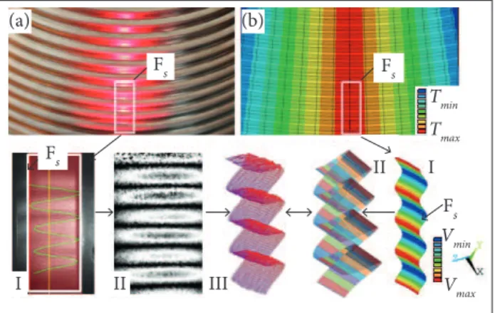
At radiation heating of the shell under the conditions, simulating with a maximum validity the regular service conditions in space vacuum, the interference patterns (shearographic interferograms) were formed (Fig. 6a, II). These patterns were obtained by comparison of two speckle-patterns corresponding to different stages of heating (Fig. 6a, I) at the reflection of the dissipated laser radiation from TVS surface part (Fig. 6a). he further processing of interference patterns using a special sotware allows plotting a three-dimensional pattern of deformations at thermal loading in the part being examined (Fig. 6a, III).
suicient coincidence degree of two models (Fig. 6a and b) can confirm both the effectiveness of surface engineering methods and the validity of the accepted computational model (correctness of calculation of structure using numerical methods) without applying full-scale stand tests. he advantage of the experimental calculation method is the possibility to obtain the interference patterns during vacuum tests with simulation of a solar spectrum and density of radiation lux applied to a TVS part. It can be a single conical segment of the multisectional structure, subjected to proportional deformations at orientation of solar radiation lux, normal to the TVS symmetry axis or to the pair of adjacent segments at any other orientation of the lux. Thus, Fig. 5 illustrates the effectiveness of the applied method of surface modifying. To verify the calculated results of its application, expressed in the deformation pattern, the described experimental-calculation method (Fig. 6), also including diferentiation of displacement ield V in the directions OY (∂V/ ∂Y) and OZ (∂V/ ∂Z), can be used.
With respect to the structure in Fig. 3b, as a result of its calculation using standard finite-element analysis, it was determined that taking into account both the efect of maximum values of temperature loads (−150 to +125 °С) and accelerations on optical surfaces without protective coating leads to 2.32 times increase in maximum displacements in the TVS shell and 1.23 times growth of equivalent stresses. Further, the change in shape of a corrugation proile (Fig. 3) allows reducing the maximum values of stresses in the structure by 15% (from 202 to 176 MPa). The application of coatings, decreasing the temperature load to the range of −43 to +63 °C, leads to the deformability decrease of the multisectional shell by 1.45 times and to the reduction of maximum values of equivalent stresses by 1.17 times (from 175 to 150 MPa). hus, the surface modiication in combination with a proile shape variation of shell folds can reduce the deformability and increase the stability of the studied TVS type to values which require the increase in the structure mass by more than 30% at simultaneous reduction of its compactness using standard design approaches (in particular, 2 times increase in material thickness of four conical sections at the attachment side). he results of calculations and their experimental veriication demonstrate the possibility to use these types of thin metal shells as the load-bearing elements under SEF conditions. It should be added that the examined example of the conical TVS can be described as the most complicated structural and technological embodiment of this type, which has a small ratio of the diameter of the supporting contour to the overall
(a)
Fs
Fs
Fs
I
I
II
II III
Fs (b)
Vmax Vmin Tmax Tmin
Figure 6. The use of the method of electronic shearography
(a) for veriication of the FEM (b) of temperature deformations of the random TVS shell fragment FS.
length and is subjected to direct radiation heating inluence on the vacuum of space environment. he determination of optimum ratio of the used surface engineering methods, as well as qualitative and quantitative evaluation of the efectiveness examined in this paper, depends, in each case, on a number of
factors — primarily, on the speciic functionality of the TVS
and the duration of its exposure under SEF.
CONCLUSIONS
The development of new shell structures, with unique functional characteristics and their adaptation to extreme service conditions, predetermines the need to verify the results of superposition modelling of complex stress-strain states,
subjected to signiicant changes in the long-time exposure process. he integrated approach, suggested by the authors, allows evaluating the equivalency of fields of TVS surface displacements, obtained in contactless diagnostics and in the databasis of numerical modelling. It also determines the optimum relation of methods used for modification of its rigidity-strength characteristics. It is shown the possibility of improving the functional characteristics of the examined structure by means of proile adjustment of circular folds of its separate shell elements and spraying on them thin coatings with required thermal and optical properties. he result of this study demonstrates the possibility of efectiveness evaluation of the applied surface engineering methods under the terrestrial conditions, excluding the valid experimental conirmation of computational model results.
REFERENCES
Ario I, Watson A (2009) Structural stability of multi-folding structures with contact problem. J Sound Vib 324(1-2):263-282. doi: 10.1016/j.jsv.2009.01.057
Ario I, Watson A (2010) Non-linear dynamic behaviour of multi-folding microstructure systems based on origami skill. Int J Nonlinear Mech 45(4):337-347. doi: 10.1016/j.ijnonlinmec.2009.11.010
Lobanov LM, Pivtorak VA (2014) Diagnostics of structures by the methods of electron shearography and speckle-interferometry. Mater Sci 49(4):442-448. doi: 10.1007/s11003-014-9635-5
Mayes RL, Miller AK, Holzmann WA, Tipton DG, Adams CR (2009) A structural dynamics model validation example with actual hardware. Proceedings of the IMAC-XXVII Conference on Structural Dynamics; Orlando, USA.
Paton BE, Lobanov LM, Volkov VS (2015) Metal transformable-volume structures for space engineering. Acta Astronaut 110:50-57. doi: 10.1016/j.actaastro.2015.01.005
Pellegrino S (2015) Folding and deployment of thin shell structures. In: Bigoni D, editor. Extremely deformable structures. vol. 562. Springer: CISM International Centre for Mechanical Sciences. p. 179-267.
Schenk M, Viquerat AD, Seffen KA, Guest SD (2014) Review of inlatable booms for deployable space structures: packing and rigidization. J Spacecraft Rockets 51(3):762-778. doi: 10.2514/ 1.A32598
Silver MJ, Warren P (2010) Dynamic modeling of the folding of multi-shell lexible composites. Proceedings of the 51st AIAA/ASME/ ASCE/AHS/ASC Structures, Structural Dynamics, and Materials Conference; Orlando, USA.