Dynamic Analysis of a valve train
system, used in a four stroke engine
João António dos Reis Nogueira
Working version
Dissertation of MIEM
Dissertation for a Master’s Degree in Mechanical Engineering
Supervisor: Professor Doutor Jorge H. Seabra
Second Supervisor: Eng. César Ferreira
used in a four stroke engine
João António dos Reis Nogueira
Dissertation for a Master’s Degree in Mechanical
Engineering
DEMec - Department of Mechanical Engineering
CETRIB - Section of Vibrations, Tribology and Industrial Maintenance Faculdade de Engenharia da Universidade do Porto
The internal combustion engine (ICE) plays an important role in our society and much work is done into improving it’s efficiency, power output and reliability. In the motorcycle world, two types of engine are being used: the two-stroke and the four-stroke engines. The latter requires the use of an auxiliary system to control the opening and closing of the valves - the valve train.
Traditionally, the valve train uses eccentric lobes to actuate rocker arms that open the intake and exhaust valves while the closing of the valves is done by the force of springs which are compressed during the opening of the valves.
The portuguese motorcycle manufacturer AJP Motos SA developed a new valve train - InnerCam - that promises the reliability and stability of more complex systems while retaining the smaller size and low gravity center of some simpler, yet less reliable, systems. Previously analysis work led to functioning prototypes that reveal the grand potential of the system. However, these tests also revealed an unidentified issue that caused a power loss in a small range of engine speeds. A new kinetic and dynamic analysis, as well as a vibration analysis on the system, are needed in order to identify the source of the power loss, mentioned above, that required to model the real mechanism into simpler systems that allow an easier approach and an expedite analysis without compromising the accuracy of the results.
This work revealed that the profiles for the valve displacement, velocity and ac-celeration are similar to the theoretical profiles required for the good engine op-eration, which helps to validate the InnerCam concept as a valid system with commercializing potential. The dynamic analysis performed also showed that the engine’s acceleration isn’t an influence to the system’s dynamic balance, neither is the variable point of contact between the rollers and the cam path. However, this variation in the point of contact implies very sharp changes in rotational speed and direction, which may increase the rate of wear of these components’ surfaces. The vibration analysis was performed on the exhaust sub-system and it revealed that the resonance frequency of this system is well above the range of excitation frequencies that the system supports (from 2000 to 12000 rpm). This rules out resonance issues, such as the source of the power loss that was previously described.
O motor de combustão interna (ICE) desempenha um papel importante na nossa sociedade e bastante trabalho tem sido feito para melhorar a sua eficiência, potên-cia e durabilidade. No mundo do motociclismo, são utilizados dois tipos de motor: motores a dois tempos e motores a quatro tempos. Este último requer o uso de um sistema auxiliar para controlar a abertura e fecho das válvulas - o trem de válvulas. Tradicionalmente, o trem de válvula usa lóbulos excêntricos para acionar os braços que abrem as válvulas de admissão e de escape, enquanto o fecho das válvulas é feito pela força das molas que são comprimidas durante a abertura das válvulas. O fabricante de motos português AJP Motos SA desenvolveu um novo trem de válvulas - InnerCam - que promete a durabilidade e estabilidade dos sistemas mais complexos, mantendo as pequenas dimensões e baixo centro de gravidade de alguns sistemas mais simples, mas menos fiáveis. O trabalho de análise anterior levou a protótipos que revelam o grande potencial do sistema em funcionamento. No entanto, estes testes também revelaram uma perda de potência anormal numa pequena gama de velocidades do motor. Uma nova análise cinemática e dinâmica, bem como a análise de vibrações sobre o sistema, foi necessária, no sentido de tentar explicar a perda de potência. Isto exigiu modelar o sistema em sistemas mais simples, que permitiram uma aproximação mais fácil e uma análise expedita sem comprometer a precisão dos resultados.
Este trabalho revelou que os perfis de deslocamento, velocidade e aceleração são semelhantes aos perfis teóricos necessários para o bom funcionamento do motor, o que ajuda a validar o conceito InnerCam como um sistema pertinente com po-tencial de comercialização. A análise dinâmica também mostrou que a aceleração do motor não influencia o equilíbrio dinâmico do sistema, nem o ponto de contato variável entre os pinos rolantes e a came. No entanto, esta variação no ponto de contacto implica mudanças muito agressivas na velocidade de rotação e sentido de rotação, que podem acelerar o desgaste das superfícies destes componentes. A análise de vibrações foi realizada para o sub-sistema de escape e revelou que a frequência de ressonância deste sistema está situada bem acima da gama de frequências de excitação que o sistema tem de suportar (2000-12000 rpm). Isto elimina os problemas de ressonância, como a fonte de perda de energia descrita anteriormente.
I would like to acknowledge and express my sincere gratitude to some people without whom I wouldn’t be able to present this thesis or even finish the master’s degree.
First of all, I thank my parents, Antero e Isabel, for all the trust and continued support. I stand where I am thanks to them.
Secondly, I’d like to acknowledge my entire family, specially my uncle António, as well as Frederica Oliveira, for all the help and support for this thesis.
Thirdly, I’d like to express my greatest gratitude to the Prof. Jorge Seabra, Prof. José Dias Rodrigues and Eng. César Ferreira, that provided me the tools, guidance and patience for this thesis to be done. For this, I also thank all the staff at CETRIB who warmly welcomed as one of them.
Fourthly, I’d like to acknowledge and thank Pedro Noronha, Carlos Vieira, Diogo Moura, Mário Oliveira,Pedro Soares, Eduardo Moreira, João Mata, Salvador Costa, Ana Ribeiro, Ana Oliveira, Susana Costa, Raquel Camacho, Samuel Pinho, Daniel Laranjinha, Luísa Vieira, Hugo Carvalho, Daniel Freitas, Guaicaipuro Neves, Ri-cardo Martins, Marta Rolo, Leonor Madureira, Carlos Oliveira, Joana Coutinho, Marta Conceição, Inês Mesquita, Luísa Louro and all my friends who accompanied me to this day. You may never know how much you’ve helped me get here, but nevertheless, thank you.
Finally, I would like to thank AJP Motos SA for their collaboration and assistance for this thesis, as well as Faculdade de Engenharia da Universidade do Porto and all their staff for their contribution to this work.
João Nogueira
Thomas A. Edison
1 Introduction 1
1.1 Dissertation Outline . . . 3
2 The engine for the PR5 5 2.1 Technical information about the engine . . . 8
2.2 Valve Trains . . . 8
2.2.1 State of the art . . . 10
2.2.2 Typical kinematic profiles for valve trains . . . 21
3 InnerCam 25 4 Dynamic Analysis 33 4.1 Exhaust sub-system . . . 34 4.1.1 Geometric Properties . . . 36 4.1.2 Kinematics . . . 37 4.1.3 Dynamics . . . 43 4.2 Intake sub-system . . . 53 4.2.1 Geometric properties . . . 55 4.2.2 Kinematics . . . 55 4.2.3 Dynamics . . . 56 4.3 Model Results . . . 58 4.3.1 Exhaust Sub-system . . . 63 4.3.2 Intake Sub-system . . . 71
4.4 Influence of engine acceleration in the valve train dynamics . . . . 81
4.5 Influence of variable point of contact between the cam and roller . 88 5 Vibration Analysis 93 6 Conclusions and Future Work 99 6.1 Conclusions . . . 99
6.2 Future Work . . . 101
References 103
A Benchmarking testes 105
B Steel’s technical sheet 109
2.1 4 stroke engine diagram, with separated strokes [5] . . . 6
2.2 4 stroke engine diagram, with separated strokes[2] . . . 7
2.3 Technical information of the standard engine [8] . . . 9
2.4 Example of a Single Overhead Valve system [9] . . . 12
2.5 An example of a Double Overhead Cam valve train [11] . . . 13
2.6 Honda Unicam engine. It’s possible to see that only one camshaft, with two cam lobes, is used. [12] . . . 13
2.7 Two valve side engine example [2] . . . 14
2.8 Example of a Four-Valve Pent-Roof Cylinder Head. [13] . . . 16
2.9 Desmodromic valve train used in Ducati motorcycles [14] . . . 17
2.10 Example of a sleeve valve system [15] . . . 19
2.11 Theoretical lift profile, velocities and accelerations of the valves. In the dotted lines, it shows the common real kinematic behaviour instead of the theoretical behaviour. [7] . . . 23
3.1 Innercam valve train - schematic representation (springs are not represented). . . 27
3.2 Innercam Camshaft. . . 28
3.3 Innercam camshaft’s cam paths. The inner path (dotted lines) cor-responds to the exhaust sub-system. . . 29
3.4 Rocker arm - schematic rendering. . . 30
3.5 Lift profiles measured through valve timing by AJP Motos SA . . 31
4.1 Exhaust sub-system schematics - position for non-actuated rocker arm . . . 34
4.2 Exhaust sub-system schematics - position for actuated rocker arm 35 4.3 ( ) - Discrete values given by AJP Motos SA . . . 37
4.4 Process of calculating the angle . . . 42
4.5 Free body diagram of the camshaft . . . 45
4.6 Free body diagram of the exhaust rocker arm . . . 46
4.7 Free body diagram of the exhaust valve . . . 48
4.8 Free body diagram of the exhaust cam follower / roller . . . 49
4.9 Free body diagram of the exhaust sub-system . . . 52
4.10 Schematic representation of the intake sub-system non-actuated . . 53
4.11 Schematic representation of the intake sub-system actuated . . . . 54
4.12 Lift ( , , ) profiles for the exhaust sub-system (engine at 12000 rpm) . . . 58
4.13 , , profiles for the exhaust sub-system (engine at 12000 rpm) . 59
4.14 , , profiles for the exhaust sub-system (engine at 12000 rpm) 60
4.15 , , profiles for the exhaust sub-system (engine at 12000 rpm) . 61
4.16 , , profiles for the exhaust sub-system (engine at 12000 rpm) . 62
4.17 profile for the exhaust sub-system . . . 63
4.18 profile for the exhaust sub-system . . . 63
4.19 profile for the exhaust sub-system at various engine speeds . . . 64
4.20 profile for the exhaust sub-system at various engine speeds . . . 64
4.21 profile for the exhaust sub-system at various engine speeds . . . 65
4.22 profile for the exhaust sub-system at various engine speeds . . . 65
4.23 profile for the exhaust sub-system at various engine speeds . 66
4.24 profile for the exhaust sub-system at various engine speeds . 66
4.25 profile for the exhaust sub-system at various engine speeds . 67
4.26 profile for the exhaust sub-system at various engine speeds . 67
4.27 profile for the exhaust sub-system at various engine speeds . . 68
4.28 profile for the exhaust sub-system at various engine speeds . 68
4.29 profile for the exhaust sub-system at various engine speeds . . 69
4.30 profile for the exhaust sub-system at various engine speeds . . 69
4.31 profile for the exhaust sub-system at various engine speeds . . 70
4.32 profile for the exhaust sub-system at various engine speeds . . 70
4.33 profile for the intake sub-system . . . 71
4.34 profile for the exhaust sub-system . . . 71
4.35 profile for the intake sub-system at various engine speeds 72
4.36 profile for the intake sub-system at various engine speeds 72
4.37 profile for the intake sub-system at various engine speeds 73
4.38 profile for the intake sub-system at various engine speeds 73
4.39 profile for the intake sub-system at various engine speeds . . 74
4.40 profile for the intake sub-system at various engine speeds . . 74
4.41 profile for the intake sub-system at various engine speeds . . 75
4.42 profile for the intake sub-system at various engine speeds . . 75
4.43 profile for the intake sub-system at various engine speeds . . . 76
4.44 profile for the intake sub-system at various engine speeds . . 76
4.45 profile for the intake sub-system at various engine speeds . . . 77
4.47 profile for the intake sub-system at various engine speeds . . . 78
4.48 profile for the intake sub-system at various engine speeds . . . 78
4.49 profiles comparison of a constant speed vs. speed and accelera-tion - 4000 rpm . . . 82
4.50 profile for the intake sub-system at various engine speeds - 12000 rpm . . . 82
4.51 profiles comparison of a constant speed vs. speed and accelera-tion - 4000 rpm . . . 83
4.52 profiles comparison of a constant speed vs. speed and accelera-tion - 12000 rpm . . . 83
4.53 profiles comparison of a constant speed vs. speed and acceler-ation - 4000 rpm . . . 84
4.54 profiles comparison of a constant speed vs. speed and acceler-ation - 12000 rpm . . . 84
4.55 profiles comparison of a constant speed vs. speed and accelera-tion - 4000 rpm . . . 85
4.56 profiles comparison of a constant speed vs. speed and accelera-tion - 12000 rpm . . . 85
4.57 profiles comparison of a constant speed vs. speed and acceler-ation - 4000 rpm . . . 86
4.58 profiles comparison of a constant speed vs. speed and acceler-ation - 12000 rpm . . . 86
4.59 profiles comparison of a constant speed vs. speed and acceler-ation - 4000 rpm . . . 87
4.60 profiles comparison of a constant speed vs. speed and acceler-ation - 12000 rpm . . . 87
4.61 Free body diagram of the camshaft . . . 88
4.62 Free body diagram of the exhaust cam follower / roller with an internal point of contact . . . 89
4.63 profiles with variable point of contact . . . 91
4.64 profile with variable point of contact (8000 rpm) . . . 92
4.65 profile with variable point of contact (12000 rpm) . . . 92
5.1 New system model created for a vibration analysis . . . 94
5.2 Simulation of the deformation of the first "arm" in body 2 . . . 98
Symbol Units Description
Distance between points A and C Distance between points A’ and C’ Acceleration of point in the direction Exhaust rocker arm hole center point Intake rocker arm hole center point
Displacement vector between points A and C Displacement vector between points A’ and C’ Distance between A and B
Distance between A’ and B’
Exhaust rocker arm-to-valve contact point Intake rocker arm-to-valve contact point BDC Bottom dead center
Exhaust roller center point Intake roller center point
DOHC Double Overhead Camshaft layout DOHV Double Overhead Camshaft layout
Force applied
Exhaust rocker arm center of gravity position Intake rocker arm center of gravity position Exhaust valve center of mass position Intake valve center of mass position
Exhaust point of contact between the roller and the cam path Intake point of contact between the roller and the cam path Moment of inertia according to the rotational direction Component’s rigidity
Dynamic component of body in the direction Component’s mass
Component’s torque ( or rotational momentum) - for component Camshaft’s center of mass position
OHV Overhead Valve layout OHC Overhead Camshaft layout
PAO Polyalphaolefin base oil
Quantity of acceleration for body xv
Symbol Units Description
Distance between the points O and C Distance between the points O and C’
Reaction force applied in point in the direction , First derivative of the function and , respectively , Second derivative of the function and , respectively SOHC Single Overhead Camshaft layout
SOHV Single Overhead Valve layout Period of vibratory response TDC Top dead center
Velocity in point in the direction Angle between and the XX axis Angle between and the XX axis
, First derivative of the function and , respectively , Second derivative of the function and , respectively
Angle between and the XX axis Angle between and the XX axis
Angle between and the XX axis for the non-actuated cycle part Angle between and the YY axis for the non-actuated cycle part Angle between and the XX axis for the non-actuated cycle part Angle between and the YY axis for the non-actuated cycle part , First derivative of the function and , respectively
, Second derivative of the function and , respectively Displacement from flexing
Valve lift (displacement)
First derivative of the function for valve lift displacement Second derivative of the function for valve lift displacement Angle between and
Angle between and
, First derivative of the function and , respectively , Second derivative of the function and , respectively
Rotational speed
Natural frequency of free vibratory response Rotational acceleration
Introduction
On 2013, a new valve train system, the InnerCam, was proposed by AJP Motos SA and was analysed (both dynamically and tribologically) by former student and now engineer, César Ferreira.
This work and development was motivated by the need to implement a valve control system that should be more compact and very reliable at high engine speeds.
Using the data collected from this analysis, AJP Motos SA was able to solve a great set of problems presented by early systems, resulting in a working set of prototypes.
A dynamic analysis on this system was previously done, with a larger focus on the lubrication between surfaces and contact mechanics between components, result-ing in few constructive changes that helped to reduce the wear between critical surfaces and improve the life cycle of the components.
The major constructive changes applied to the InnerCam consisted on thermal surface treatments, such as nitriding, applied to key components and the inclusion of upgraded lubrications circuits, which allowed to remove debris, improve the contact between bodies and significantly reduce wear in the system, improving the overall system life cycle.
This work led to working prototypes that revealed the potential to reduce fuel consumption and improve the power output of engines fitted with the InnerCam. Although the newer prototypes are already reliable enough to be assembled in test motorcycles, a few problems were diagnosed during these tests. There seems to be an issue with the engine that is causing an unusual power loss in the engine. This power loss only happens between the 8000 and 10000 rpm (see appendix A). Since the only new factor in play is the new valve train system, an improved analysis was required to explain this power loss.
The goal of this dissertation is an improved and more precise dynamic analysis of the Innercam mechanism, resulting in kinematic and dynamic models for this valve train, in particular, and a vibration analysis of the system, as well. With this analysis, a better understanding of the theoretical behaviour of this system is expected, serving as a benchmark against experimental measures that may be done in the future.
The main contribution of this work will be a solid theoretical basis for the required dynamic behaviour of the InnerCam, helping to adjust the system real operation in order to improve the performance of the engine and, consequently, the entire motorcycle.
1.1 Dissertation Outline
On chapter 2, several types of valve train, as well as the functions of these parts in the operation of a four stroke engine, are presented.
On chapter 3, the InnerCam system is presented in detail.
On chapter 4, the mechanical analysis is presented. It consists on a kinematic and dynamic description (modelling) of the system as well as an analysis on the model results.
On chapter 5, a vibration analysis of the system is presented, continuing the analysis on chapter 4.
On chapter 6, the final one, the conclusions of this work are presented as well as suggestions for future work.
The engine for the PR5
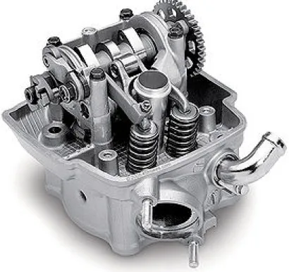
Before starting a detailed analysis of the valve train proposed by AJP Motos SA, it’s important to overview the system where the valve train will be applied. The engine used for these motorcycles is a 4-stroke mono-cylinder gasoline engine with 4 valves with liquid cooling, manufactured by Zongshen, and employs a single over-head camshaft for the valve train system. This engine is the result of a joint venture between Zongshen and an European company. [1]
The main goal of AJP Motos SA is to replace this valve train system with the InnerCam system, resulting in a more powerful, compact and reliable engine, especially at higher speeds and accelerations.
The traditional spark-ignited 4-stroke engine is based on 4 phases that correspond to the filling and emptying of the cylinder. These phases have the following denomination: Intake stroke; Compression stroke; Power stroke; Exhaust stroke; 5
In the intake stroke, the intake poppet valve is opened (through the action of the valve train) allowing a mixture of air and fuel to enter the chamber. As soon as the piston reaches its bottom dead center(BDC), the intake poppet valve is closed and the compression stroke is initiated. Since the piston is fitted with sealing rings, there’s no loss on matter between the bottom dead center and the top dead center (TDC), allowing to properly compress the air-fuel mixture. [2] [3]
As soon as the piston reaches its top dead center, the spark-plug ignites the air-fuel mixture, initiating the power stroke. In this stroke, the pressure and temperatures in the chamber reach very high values (tens of thousands of atmospheres of pressure and thousands of degrees Celsius). The energy generated from the explosion of the air-fuel mixture, allied to the big pressure differential, propels the piston and, consequently, the crankshaft, allowing to propel the rest of the pistons through their own intake and compression stroke, for example. [2][3]
As soon as the piston reaches its bottom dead center, the exhaust stroke is initiated and the exhaust poppet valves are opened, allowing the post-combustion gases to be expelled from the cylinder, clearing the cylinder for the new combustion cycle. For every combustion cycle, or 4-stroke cycle, it corresponds to 2 piston cycles. [3] [4]
These 4 strokes are further described in the figure 2.1.
On a 4-stroke engine, a valve train is required in order to control the opening and closing of the valves, unlike the 2-stroke engines, in which the valves are controlled and actuated directly by the crankshaft. For an engine to work properly while maintaining low emissions, high power output and a low level of noise, it’s imperative that every component of the engine works together with the rest of the system flawlessly. [2] [6] [7]
The opening and closing of the valves must be very precise and should directly depend on the 4 stroke cycle on the engine. On the next figure, an example of the valve lift defined for a 4 stroke cycle in an engine is presented (figure2.2).
Figure 2.2: 4 stroke engine diagram, with separated strokes[2]
The capital relevance of the valve train system becomes obvious, since it allows to properly control the admission an exhaust on the engine and prevent any collisions between the pistons and the valves, preventing the engine’s malfunction. In fact, the more developed the valve train is, the more efficient is the engine [2] [6].
2.1 Technical information about the engine
As previously presented, the engine fitted in the PR5 model - ZS177MM - is man-ufactured by the Chinese company Zongshen and was developed in collaboration with an European company [1].
According to the manufacturer, this engine, without any tune up from AJP Motos SA, develops 19 kW (aprox. 25,85 BHP) of power (at 9000 rpm). AJP Motos SA then modifies this engine, introducing an electronic fuel-injection system and a high performance exhaust pipe. With these tune ups, the engine can now develops 20,2 kW (aprox. 27,08 BHP) of power (at 8000 rpm), a respectable increase in power.
In terms of lubrication, the engine has 2 oil pumps, one for the gearbox lubrication and another for the rest of the system. It uses a polyalphaolefin (PAO) oil - ENI I-RIDE 20W50 supplied by ENI, as part of a partnership between AJP Motos SA and a Portuguese agent of ENI. Further technical specifications of the engine can be found in figure 2.3.
2.2 Valve Trains
Internal combustion engines require a cyclic supply of fresh air, as well as the removal of post-combustion gases. As seen above, the 4-stroke engines require the use of valve trains.
The valve train is required to:
1. Perform the opening and closing of the valves rapidly; 2. Clear the largest opening diameter;
3. Have a streamlined design in order to reduce pressure losses; 4. Ensure an effective sealing when the valves are closed;
Figure 2.3: Technical information of the standard engine [8]
The valve train is composed by the joint operation of poppet valves, their actu-ating parts (rocker arms, lobes, push rods, etc.), and the camshaft driven by the crankshaft’s gear wheel (through a drive belt).
The design of a valve train will depend on:
1. The arrangement of the valves in the cylinder block (overhead valves or side valves, for example);
2. The geometry of the combustion chamber;
4. The design of the camshaft and the rocker (one- or two-arm levers or lobe rockers, for example);
5. The number and type of springs;
6. The type of drive applied in the camshaft.
Only valve trains that can ensure a good gas exchange in the engine, both at low and high speeds, are currently used in the most modern engines. It’s vital to maintain the optimal flow of matter (air and fuel mixture) in the engine, preferably in the entire range of speeds and accelerations of the engine. [6] [7] [2]
In order to make the valve train more rigid, it’s advisable to position the camshaft the closest possible to the valves. This way, it’s possible to reduce the flexing and compressing of the valve train components, reducing the vibrations in the system and the noise generated in the operation, and reduce the possibility of the tappets to jump of the cam as well [6].
Thus, valve trains with shorter push rods tend to have better behaviour at higher engine speeds - this is usually associated with overhead cam systems. [6]
It’s also recommended to use highly rigid springs, in order to counter the effects of the larger forces of inertia at higher speeds of the engine and to prevent harmful phenomenons like "valve float" or "valve bounce". The "valve float" phenomenon happens when the closing of the valves is not synchronized. The "valve bounce" consists on the unintended movement of the valves thanks to their inertia combined with the resonance of the springs.
Any one of these phenomenons can impair the performance of the engine and even lead to serious damage of the valves (in case they slam of the piston, for example)[6].
2.2.1 State of the art
As it was previously presented, the valve train plays a vital role in the opera-tion of a 4-stroke engine. It’s this system that properly opens or closes de intake
and exhaust valves, allowing a proper mass flow control of fuel and air inside the combustion chamber. It’s not surprising, then, to see many valve trains systems. There’s a constant interest in the development of new valve trains that can boost the power output while reducing the noise and gas emissions of the engine, achiev-ing that goal in the most compact way in order to further improve manoeuvrability and reduce weight.
There are many designs for the valve train and usually they’re distinguished by the number of valves drives and the number and position of the camshafts.
2.2.1.1 Overhead Valves (OHV)
This is, probably, the most common type of 4-stroke engine produced. There are various options on the number of valves for each cylinder but the most common is the two valve system, one for intake and one for exhaust. This denomination derives from the fact that the valves are located above the combustion chamber. The actuation of the valves can be accomplished by the use of a single cam - Single Overhead Valves (SOHV) - or by the use of two cams - Double Overhead Valves (DOHV).
In figure2.4, a SOHV valve train is displayed. It’s possible to see that the actuation of the valves is done by the rocker arms that are, in their turn, actuated by the cams located in the single camshaft, next to the combustion cylinder.
2.2.1.2 Overhead Cam (OHC)
In this valve train design, the camshaft actuating the valves are located above the combustion chamber, just like the valves. If there’s only one camshaft actuating both intake and exhaust valves, the system is called Single Overhead Cam (SOHC). If the system employs two camshafts, one for the intake valves and one for the exhaust valves, it’s called Double Overhead Cam (DOHC). An example of this layout is presented of figure2.5.
Figure 2.4: Example of a Single Overhead Valve system [9]
One good example of the SOHC system is the Honda Unicam (see figure 2.6). Developed by the japanese manufacturer Honda, this system relies on a single overhead cam for the actuation of both the intake and exhaust valves. This system has been applied to their dirt motorcycle line. [10]
In this system, the camshaft directly actuates the admission valves and the two ex-haust valves are operated through low-friction roller rocker arms. A roller bearing on the rocker arms reduces the friction and wear, which allows for the cam lobes to be narrower, smaller and lighter than conventional rocker arms, contributing for a lighter engine.
This results in a much more compact, lighter, ideal for off-road bikes, in which the weight of the engine is an important fact to take into consideration since it directly affects the handling of the motorcycle. This system also improves the
breathing and the flow on the engines, resulting in great power output.
Figure 2.5: An example of a Double Overhead Cam valve train [11]
Figure 2.6: Honda Unicam engine. It’s possible to see that only one camshaft, with two cam lobes, is used. [12]
2.2.1.3 Two Valve Side Engine
The two valve side engine, or flathead engine, is a valve train design that was used in the 1940’s and 1950’s and it was quite popular among the engine producers,
through the simplicity of the system. This valve train consists on placing both the admission and exhaust valves on the side of the combustion chamber, parallel to the chamber. Due to geometric limitations of this design, it wasn’t possible to fit more than one intake valve and one exhaust valve. It’s also visible in figure 2.7
that the bore in which all the air flow must pass to enter the chamber is small, limiting the breathing capabilities of the engine. This engine also suffered from low compression rates. All these design problems resulted in an engine with a low power output [2].
Figure 2.7: Two valve side engine example [2]
This type of engines had some advantages, such as the simplicity of the engines (which made it very easy to produce), their cheapness and compactness. It was also insensitive to lower-octane fuel, making it versatile, and had a good response at lower rotational speeds.
This type of engine was frequently applied in some cars - like the Ford Model T - and in motorcycles, especially in the 1950’s Harley-Davidsons’. These bikes
became famous for the low-rev engines with good torque output, enabled by this engine design.
2.2.1.4 Four-Valve Pent-Roof Cylinder Head
This is currently the most used valve train and was first introduced in racing vehicles. Afterwards, the japanese motor industry started applying this design to their consumer vehicles [2].
This design sets itself apart by placing the valves in the side of a wedge (the pent-roof name comes from this characteristic), allowing for bigger valves and larger valve areas and, consequently, better breathing conditions of the engine. Additionally, there’s a possibility to fit the spark plug on the center of the com-bustion chamber, allowing for equal flame paths from the spark plug to the sides of the chamber, resulting in a balanced explosion and application of the pressure resulting from the explosion [2] [7].
This design can be applied together an overhead valve system or an overhead cam system. Usually, the DOHC layout is used [2]. An example of this system (with the inclusion of a DOHC layout) is presented in the fig. 2.8.
2.2.1.5 Desmodromic Systems
A desmodromic valve is a reciprocating engine valve that is positively opened and closed by a cam and leverage system, rather than being closed only by a more conventional spring.
An engine using typical desmodromic valves has two cams and two actuators, each for positive opening and closing without a return spring. Although the closing of the valves is actuated by a cam, springs can still be applied in the system in order to hold the valves in their place during the closed time.
The desmodromic valves can take many mechanical forms, usually depending on the manufacturer.
Figure 2.8: Example of a Four-Valve Pent-Roof Cylinder Head. [13]
This mechanism was inspired by the necessity to have a valve train that could work properly at high rotations, since the common valve spring system usually doesn’t work properly at high speeds. In fact, when desmodromic systems were first applied, it was commom for the typical spring-valve engines to fail after some time because the springs broke due to the wear and fatigue.
At very high rotational speeds, it is required the use of very rigid and strong springs to avoid valve float. The use of such rigid springs leads to other problems. At high speeds, the acceleration of the valve train components can be very high, resulting in great inertia forces during the actuation of the poppet valves. This will eventually result in fatigue on the cam follower and add lubrication issues in the cam, increasing the friction losses in the valve train.
The desmodromic systems tries to solve these issues by decreasing the dependence on the spring-valve mechanism since the opening and closing of the valves is done by camshafts.
Thanks to this change, the cam is only required to supply the force to accelerate the valve train components, vastly reducing the friction at lower speeds. Valve float is also greatly reduced.
Although this concept dates back to the beginning of the internal combustion engine, the first use of the desmodromic valve was on a 1914 Delage. After that, the system was implemented on a 1922 Rolland-Pilain and on 1954 and 1991 Mercedes-Benz’s.
Also, the Italian motorcycle manufacturer Ducati has been using desmodromic valve trains since 1955, becoming the trademark of their engines (see fig. 2.9).
Figure 2.9: Desmodromic valve train used in Ducati motorcycles [14] This system has, of course, their disadvantages. First of all, most of the issues detected in the more common sprung-valve trains can currently be solved with
some adjustments. This adjustments rendered technologies like valve adjustment, hydraulic tappets, push rods and valve float adjustment, obsolete.
Secondly, since this system depends on the use of one camshaft for the opening of the valves and another camshaft for the closing, as well as two rocker arms, this leads to a heavy system, adding inertia forces to the delicate dynamic equilibrium that is required.
Thirdly, this is a more expensive and complex system than the traditional spring-valves set.
This technology was often abandoned and recovered years after, each time proving his added value to the engine technology.
2.2.1.6 Alternative Systems
It is also important to refer some of the lesser known valve train designs. Some of them influenced the development of the most common ones, already addressed above, but there are also new solutions for the valve train result from the contin-uous effort to improve the engine and his inner mechanisms.
Sleeve Valves Engines
One of these alternative systems is the sleeve valves system.
In this system, the pistons run in an inner sleeve that runs on an outer sleeve which, itself, runs in the cylinder bore.
Each sleeve has intake and exhaust bores. When the inner and outer sleeves align the bores, the air flow can move to or from the cylinder, corresponding to the intake and the exhaust, respectively (see figure 2.10).
For the sleeves to properly slide on one another, they must be flooded with lubricating oil. Since the sealing between the the oil of the sleeves and the intake/exhaust bores is very difficult to achieve, there was usually some contamination of the mass flow in the cylinder, resulting in exhaust gases
Figure 2.10: Example of a sleeve valve system [15]
with oil (followed by a blue smoke coming from the exhaust pipes of the engine) [7].
The system was very quiet and trouble-free, but the oil leakage and subse-quent dark exhaust gases, allied with the development of the spring-valve systems (better sound isolation using damping valve covers, for example), made the sleeve valve system obsolete [7].
Camless Valve Engines
On the past few years, some manufacturers have been investigating the pos-sibility of building engines without camshafts for the actuations, or even push rods, rocker arms and all the components of the typical valve train. The main advantages of these systems is their ability to infinitely control the valve timing, allowing an optimal volumetric efficiency through out the range of speeds in the engine. It also grants bigger power outputs, lower emissions and noise, and bigger fuel economy.
The different types of camless valve actuating systems that are being devel-oped can be classified in two groups: electrohydraulic and electromechanical. When it comes to electromechanical valve trains, there are several designs that are being trialled. Most developers are using the conventional poppet valve system but an alternative is a ball valve set up. Both use electromag-nets in one way or another to open and close the valve.
The electromechanical poppet valve system uses an armature attached to the valve rod.The outside casing contains a magnetic coil that can be used to either attract or repel the armature and, therefore, opening or closing the valve.
Most early systems employed solenoid and magnetic attraction/repulsion actuating principals, using an iron or ferromagnetic armature. These types of armatures limited the performance of the actuator because they resulted in a variable air gap, causing variations on the magnetic force. In order to maintain high forces on the armature as the lift of the valves increases, a higher current is employed in the coils of such devices. This increased current leads to higher energy losses in the system and a non-linear behaviour that makes it difficult to obtain adequate performance. The result of this is that most of such designs have high seating velocities (the initial opening and the end of the closing of valves is very fast and creates an impact between the surfaces) and the system cannot vary the amount of valve lift.
The electromechanical valve actuators of the latest poppet valve design elim-inate the iron or ferromagnetic armature by replacing it with a current-carrying armature coil. Combining the effects of a generated magnetic field along with the direction of the current passing through the armature coil, it allows to fully control the opening and closing of the valves, eliminating the variation of magnetic force as function of the lift (the main problem with the original eletromechanical valve actuators) [16] [17].
The ability of the electromechanical valve actuator to generate force in either direction and to vary the amount of force applied to the armature in either
direction is an important advantage of this design. It allows, for example, to vary the speed of opening and closing valves, granting a greater control over the behaviour of the engine through out its various speeds. This method can also be used to slow the valve in order to reduce the seating velocity, thereby reducing wear as well as the resulting noise [16] [17].
Originally created for the Apollo space program, the electrohydraulic valve actuator works by sending pressurised hydraulic fluid to the engine valve to move it open or closed [16].
In general terms, the latest designs of electrohydraulic valves are based on poppet valves that are moveable between a first and a second position. It uses a source of pressurised hydraulic fluid and a hydraulic actuator coupled to the poppet valve. The motion between a first and second position is the response to the flow of the pressurised hydraulic fluid. An electrically op-erated hydraulic valve controls the flow of the pressurised hydraulic fluid to the hydraulic actuator. The use of engine oil as the hydraulic fluid simpli-fies and lowers the cost of the design by removing the need for a separate hydraulic system [16].
A R&D company for the supercar manufacturer Koenigsegg has recently un-veiled a prototype of their take on the camless engine, in which the actuation of the valves is done by pneumatic actuators [18].
2.2.2 Typical kinematic profiles for valve trains
In order to fully understand the kinematic and dynamic properties of the In-nerCam, it’s advisable to first look at some information available about current systems being used. There has been plenty of work done in order to determine the lift profile, as well as the velocities and accelerations profiles for the same valve train which lead to some lift position, velocity and acceleration profiles.
Although the valve train systems developed already to this day greatly differ from one another (from a mechanical point of view), the lift’s position, velocity and
acceleration profiles are usually very similar to the profiles shown above, since these profiles were designed to improve the efficiency of the engine.
This grants a benchmark for the profiles that need to be determined for the current Innercam system.
It’s interesting to analyse the fast variation of acceleration (presented in figure
2.11) in the movement of the valves. This can lead to high inertial forces that may impair the dynamic behaviour of the valve train.
Of course the kinematic profiles of real systems differ from the theoretic profiles. It’s expected that the Innercam system generates lift position, velocity and accel-eration profiles similar to the ones already presented.
Figure 2.11: Theoretical lift profile, velocities and accelerations of the valves. In the dotted lines, it shows the common real kinematic behaviour instead of the theoretical behaviour. [7]
InnerCam
The InnerCam system is a valve train mechanism introduced by AJP Motos SA, a portuguese motorcycle manufacturer specialized on off-road bikes. Since the PR5 is the flagship of the AJP Motos SA motorcycles, there’s a high demand from the costumers and professional racers for a more powerful motorcycle, in order to give the competitive edge they always require.
Before proposing a new valve train, there were some few trials on other solutions that could improve the engine. First, they tried to increase the engine revolution per minute by altering the electronic central unit as well as adding an electronic fuel injection system. Although they improved the power output, they found some durability issues in the standard valve train used at the time.
The standard engine uses a single overhead cam in its valve train (SOHC), which performs well at lower speeds and allows for a compact engine. Actually, the greatest strength of the PR5 is its manoeuvrability; besides, the compact engine with a low center of gravity is one of the main reasons for the good handling of the motorcycle.
One of the solutions was to adapt the engine from a SOHC to a DOHC, since the DOHC engines perform well at high engine speeds. However, since the DOHC valve train is larger and more complex, this would result in a bigger engine, com-promising the manoeuvrability of the PR5.
The other solution is to create a new valve train system that is just as compact as the standard valve train and could offer the same level of performance that the DOHC engines provide. Since AJP Motos SAis a small manufacturer, without the ability to produce their own engines and the engine is provided by an european-chinese joint venture, the new valve train must be compatible with the standard engine and must be designed in order to fit in this engine.
The valve train proposed is based on the SOHC design present in the original en-gine, with several modifications on the valves, rocker arms, springs and camshaft. As shown in the figure 3.1, the new camshaft has two inner cams, one for the ac-tuation of the admission valves and one for the acac-tuation of the exhaust valves. In order to further reduce the size of the engine and improve the dynamic behaviour, new rocker arms were made for this system. Each rocker arm will move 2 valves for the admission sub-system and 2 valves for the exhaust valves. To further reduce the inertia forces in the system (improving the kinematic and dynamic behaviour of the valve train), a new set of lighter valves were installed. Two springs maintain an upward force on the valves, guaranteeing the seal required for the engine to work properly when the valves are closed.
When the cam follower reaches the non-circular trajectory, it forces the rotation of the rocker arms, causing, in turn, the opening of the valves. At low speeds, the springs can force the valves to close, as soon as the rocker arm can rotate anti-clockwise when the cam trajectory allows it. At higher speeds, though, the inertia of the components is too high and the springs alone can’t close the valves and push the rocker arm into the resting position. So, the inner surface of the cam will perform the rotation of the rocker arm into its resting position, leaving the springs to only move the valves, guaranteeing the sealing required for the engine to work properly. This allows the usage of lighter springs, since it’s not required a great stiffness given that, at higher speeds, the springs only need to move the valves. As the inertia is significantly lower than the one corresponding to regular engines, it’s less likely to occur the "valve bounce" phenomenon.
The cam features two paths for two cam followers simultaneously, allowing to control de admission and exhaust with only one cam. This is a completely new
Figure 3.1: Innercam valve train - schematic representation (springs are not rep-resented).
component and its production is made exclusively by AJP Motos SA. The camshaft is machined from a single block of steel which is, afterwards, submitted to a thermal treatment different from the one applied in the original camshaft. The steel is provided by the portuguese company F. Ramada (see appendix B for the full technical sheet of the steel and the appendix C for the report on the thermal treatment applied). Its chemical composition is presented in table 3.1.
Table 3.1: Chemical composition of the steel used to manufacture the camshaft
C Si Mn Cr Mo Ni
0.34% <= 0.40% 0.65% 1.50% 0.22% 1.50%
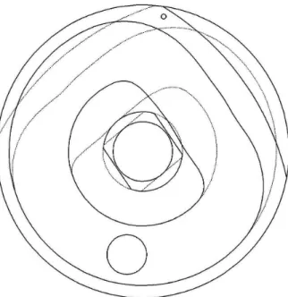
The first version of the camshaft feature a flawed design. The edges between the circular path and the non-circular path were too aggressive, resulting in very high accelerations deriving from the sudden changes in direction. The newer
prototypes display a smoother path, reducing the extreme variations in velocity and acceleration, reducing the wear on the cam and the cam follower (see figure
3.2).
Figure 3.2: Innercam Camshaft.
The new rocker arms feature an entire new design, incorporating a cam follower that is assembled in the respective cam path (see figure 3.4). This cam follower consists on a roller mounted in the rocker arm, which rotates from the contact between the roller and the cam. The cam follower forces the movement of the rocker arm as a function of the position of the cam. If the cam follower is in the non-circular path defined in the cam (see figure 3.5), the roller (and subsequently the rocker arm) will rotate around its support, causing the actuation of the valves. The new rocker arm also features the tuning bolts found on the original rocker arms. This tuning bolts allow to adjust the free space between the rocker arm and the valves. This open space must be determined with great care in order to account for dimensional variations from thermal expansion and wear on the components. If the spacing is too short, it may lead to problems such as, for example: the valves can open too soon and close too late leading to dangerous accumulations of heat; the valves may not close entirely, allowing for exhaust gases and flames to fire back into the intake valves. If, on the other hand, the spacing is to big, it may cause the valves to open later and close earlier than they should,
Figure 3.3: Innercam camshaft’s cam paths. The inner path (dotted lines) corre-sponds to the exhaust sub-system.
compromising the amount of fuel mixture in the chamber and thus reducing the performance of the engine.
The springs currently used in the Innercam system are provided by a North Amer-ican company, and these are the same springs currently used on the Yamaha YZF 250. They are characterized by a rigidity of 25400 N/m and are assembled with a 2 mm of pre-deformation. This allows a positive force from the spring, maintaining the valves closed and sealed in the normal, non-actuated, behaviour of the valve train.
Since the new valve train is considerably different from the original one (the camshaft, for example, is significantly larger than the factory camshaft), a new cylinder head must be fabricated in order to house the new system. This new cylinder head was manufactured by sand casting, and it already includes de ad-mission and exhaust ducts.
AJP Motos SA also provided some numeric values of the valves’ lift as a function of the rotation of the camshaft (see figure 3.5), allowing to determine lift profile generated by the Innercam system. The dots corresponds to the values given by
AJP Motos SA. These values also allows to determine the basic geometric relations for the system, which are presented in the next chapter.
By comparing the lift profiles generated by the Innercam (figure 3.5) and the theoretical lift profiles discussed in the chapter 2(see figures2.2and2.11), we can see that the new system develops similar lift profiles and is able to generate the distinct exhaust lift profile and intake lift profile.
(a) Front view (b) Top view
(c) Left view (d) Right view
0 1 2 3 4 5 6 0 1 2 3 4 5 6 7 8 9 θ [rad] lift [mm]
Lift of the valves depending on the camshaft’s rotation
Exhaust valves lift Intake valves lift
Dynamic Analysis
It’s possible to simplify the system that is being analysed into a 2D mechanism. This can be achieved since there are no movements along the ZZ axis, or any rotations along any other axis but the ZZ axis.
We can simplify it further by separating the admission and exhaust sub-systems. These sub-systems are identical and are actuated depending on the cam rotation. Regarding the function of the valve trains system, the opening and closing of the intake valves must occur in a different part of the combustion cycle as the opening and closing of the exhaust valves, as explained on chapters 2 and 3.
One more possible simplification is to consider the mass of the set valve-spring as a single mass, considering the mass of the spring as a part of the valve’s mass - all placed in the valve’s initial center of gravity. Although it’s common to not consider the weight of springs in some dynamic analysis, this can only be done when the weight of the springs, in comparison to the weight of the other components, is very small.
In this system, the weight of the springs is comparable to the rest of the compo-nents of the Innercam, so, the weight of the springs must be taken into account in the kinematic and dynamic analysis of the system.
4.1 Exhaust sub-system
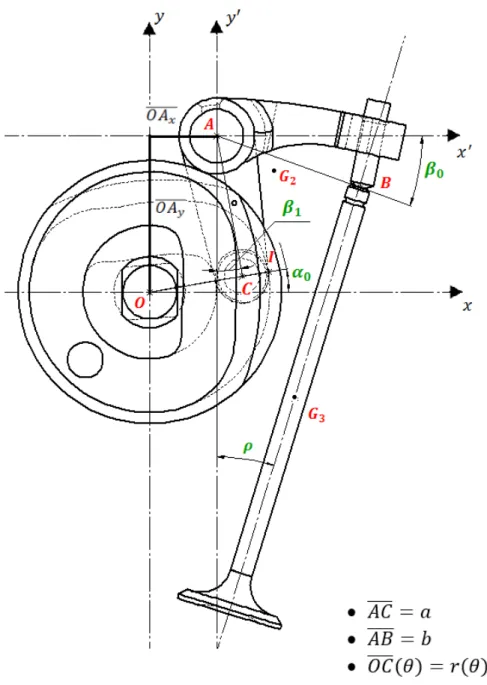
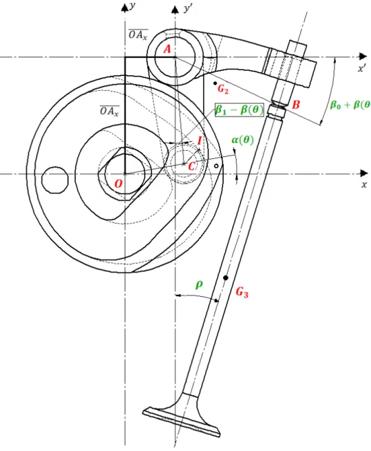
The exhaust sub-system can be defined by the following schematics (see figure4.1
for the non-actuated exhaust sub-system and the fig. 4.2 for the actuated exhaust sub-system):
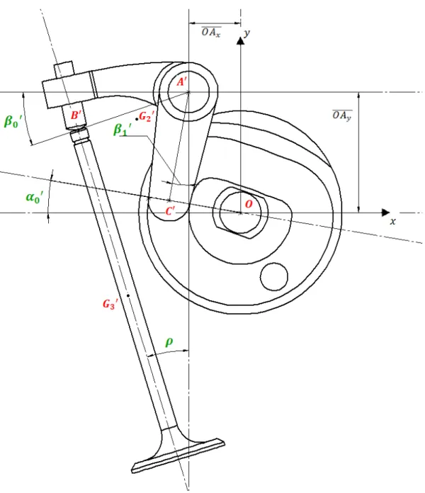
4.1.1 Geometric Properties
Considering the geometry of the exhaust sub-system, we can determine the ge-ometric relations between the lift ( ) and the remaining variables "r" (distance between the point O and C), (the angle between "r" and the xx axis) and (the angle of rotation of the rocker arm). The variable and correspond to the distance between the point A and C and the distance between the point A and B, respectively.
(4.1)
(4.2)
(4.3)
It was given access to a set of points (through a valve timing analysis per-formed by AJP), allowing to determine an analytical expression using numeric regression. Since the curve is similar to a Gaussian curve, it was used a Gaussian regression as well as a polynomial regression. The gaussian equations offer a better numeric approximation when compared to the polynomial equations. Therefore, the following work was done using gaussian equations to describe .
Using the numeric expressions of and the geometric relations displayed above, we can calculate the value of and , using equation 4.1, and the values of r,
0 1 2 3 4 5 6 7 −1 0 1 2 3 4 5 6 7 8 θ[rad] Lift [mm] Lift − ∆[θ]
Measured lift values Gaussian Equation Polynomial Equation
Figure 4.3: ( ) - Discrete values given by AJP Motos SA
4.1.2 Kinematics
We can define the displacement, velocities and accelerations for point C, using the following expressions,
Body 1 - Cam
(4.4)
(4.6)
(4.7)
Body 2 - Rocker Arm
Considering the rocker arm as the reference, we can obtain the following expressions:
(4.8)
(4.9)
(4.11)
Since point C is common to both bodies 1 and 2 (there’s no relative dis-placement between the two bodies in this point), must be equal to . The same principle is applicable to the accelerations ( ).
This can be used as a method to verify the kinematic equations determined as well as to verify the generation of , and .
Using the same reference (point A) and the same method applied before, we obtain the following expressions for point B:
(4.12)
(4.13)
(4.14)
Using the SolidWorksR TMtools available in the InnerCam schematics, it’s
possible to determine the precise location of the center of mass in all the bodies that belong to the InnerCam. This way, we can also determine the
kinematic properties on the center of mass in bodies 2 and 3 (the center of mass in body 1 is the origin of our referential).
(4.15) (4.16) (4.17) Body 3 - Valve (4.18) (4.19)
(4.20) Body 4 - Roller (4.21) (4.22) (4.23) (4.24)
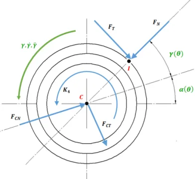
It is also required to define the position of the point of contact between the cam and the roller - point I. Usually, the point of contact between these 2 bodies is located on the outer cam path, due to the spring force. For the purposes of this calculations, it’s considered the outer point of contact.
(4.25)
Since the angle is yet to be defined, we can calculate it by determining the angle between the perpendicular line to a secant constructed by the points and (see figure 4.4), and the horizontal referential. By doing so, we are able of calculate the angle gamma for points. The first and last value of gamma are determined by a linear extrapolation of the remaining values.
Figure 4.4: Process of calculating the angle
Now that we have all the values of defined, we can apply the same numeric regressions to this variable, allowing us to determine the expressions for , and .
4.1.3 Dynamics
In order to determine the dynamic expressions for this system, it’s first required to properly determine the mass and inertia properties of each body, in order to fully define the dynamic equations.
Using the SolidWorksR TMtools available, we can obtain the various values of mass
and inertia, presented below: kg
kg
kg (considering the weight of the springs) kg
Moments of Inertia - Cam
(4.26)
Moments of Inertia - Rocker Arm
(4.27)
Moments of Inertia - Valve
Moments of Inertia - Roller
(4.29)
The main goal is to determine the correct expression for the equation of motion of the complete, rigid system. In order to do so, we can either analyse each body separately or analyse the whole system at once.
Analysing the whole system at once would give us only 3 equations and more than 3 unknown variables, so, it’s still required to analyse some bodies separately, in order to define some of the unknown variables.
If we analyse each body separately, we will obtain 3 equations (in a 2D problem) for each body (2 equations for the forces equilibrium and 1 equation for the momentum equilibrium). This will give us 12 equations in total, more than enough to fully define all the forces and momentums actuating in the system.
Analysing the cam, we obtain the following free-body diagram, accompanied by their dynamic equilibrium equations:
Body 1 - Cam
(4.30)
(4.31) (4.32)
Figure 4.5: Free body diagram of the camshaft
(4.33)
(4.34) Applying the same principle for the rest of the bodies, we can obtain the diagrams presented next.
Body 2 - Rocker Arm
Figure 4.6: Free body diagram of the exhaust rocker arm
For the forces described in the free body diagram of the rocker arm (fig. 4.6), we obtain the following equations:
(4.35)
(4.36) (4.37)
(4.38)
Body 3 - Valve
For the valve, a different coordinate system was used, parallel to the orien-tation of the valve, in order to simplify the equilibrium equations (see figure
4.7).
(4.39)
(4.40)
(4.41)
Body 4 - Roller
For the roller, it’s used the same coordinate system as in the cam and rocker arm (see figure 4.8).
Figure 4.8: Free body diagram of the exhaust cam follower / roller
(4.43)
(4.44) (4.45)
(4.46)
(4.47) We end up with 11 equation. While 10 of them allow us to define every force that are currently unknown (4.31,4.32,4.36,4.37,4.38,4.44,4.45,4.40,4.41,
4.70), the remaining one is the equation of motion (4.34), or the equation that describes the movement of the whole system, considering it rigid. Complete System - Validation
For validation purposes, we can analyse the whole system at once (see figure
4.9), in order to verify the equation of movement obtained by the analysis of each body separately. For this purpose, only the forces exterior to the sub-system are considered.
(4.48)
(4.49) Since the body 1 has only a rotational movement, the quantity of acceleration of the cam is null. The body 3 (valve) only has a translational movement,
hence the dynamic momentum of this body is equal to 0, further simplifying the equilibrium equations for the system.
(4.50)
(4.51) With these equations, we now have the proper tools to evaluate the kinematic and dynamic properties of the system, allowing us to determine the points that are more susceptible to greater velocities, accelerations and forces.
4.2 Intake sub-system
For the intake sub-system, the same principles from the last chapter are applicable. Since the pathway that controls the intake valves is different from the pathway that controls the exhaust valves, different lift profiles are expected, as well as a new dynamic behaviour. The intake sub-system can be defined by the following schematics (see figure 4.10for the non-actuated intake sub-system and figure 4.11
for the actuated intake sub-system):
4.2.1 Geometric properties
For the intake sub-system, the same approach as the one applied in the exhaust sub-system was used, with the only difference being the coordinates of the relevant point in this sub-system.
4.2.2 Kinematics
The kinematic properties for this sub-system will reflect the different position of the subsystem, regarding the coordinate system that was previously adopted. Besides, these properties are expected to be in the same order of magnitude as the kinematic properties calculated for the exhaust sub-system, since the design (and therefore, all the geometric relations between points) is the same. The points in this system will follow the same lettering rule applied in the exhaust sub-system, with the addition of an apostrophe in each point, in order to distinguish each sub-system.
In order to avoid repeating the same equations and principles applied in the pre-vious sub-chapter, we will only present the displacement vectors (in order to show the main differences between the two sub-systems) and relevant equations that differ from the approach taken in the analysis of the exhaust sub-system.
(4.52)
(4.53)
(4.55)
(4.56)
4.2.3 Dynamics
Before calculating the forces that are applied in this sub-system, we first need to determine the mass and inertia properties of the components of the sub-system. Although this system is very similar to the exhaust system, their greater differences lie in the mass and inertia properties, as it can be verified by the following values:
kg kg
kg (considering the weight of the springs) kg
Moments of Inertia - Cam
(4.57)
Moments of Inertia - Rocker Arm
Moments of Inertia - Valve
(4.59)
Moments of Inertia - Roller
(4.60)
It’s important to note the differences between the inertia matrices of the intake and exhaust rocker arms. The intake rocker arm has lower inertia values. This is important to reduce the inertial forces caused by the higher lift values.
4.3 Model Results
Since all kinematic and dynamic equations are fully defined, it’s possible to obtain the graphics showing the variation of position, velocities and accelerations, as well as the variation of the forces generated within the system. These graphics were generated for various engine velocities, corresponding to the lower, medium and higher regime of the engine.
0 1 2 3 4 5 6 7 −2 0 2 4 6 8 10x 10 −3 θ /[rad] ∆ /[m]
∆(θ) − Opening displacement of the valve as a function of the rotation of the cam ∆exhaust(θ) ∆intake(θ) 0 1 2 3 4 5 6 7 −0.015 −0.01 −0.005 0 0.005 0.01 θ /[rad] ˙ ∆/ [m/ s]
Velocity of displacement of the valve as a function of the rotation of the cam ˙ ∆exhaust(θ) ˙ ∆intake(θ) 0 1 2 3 4 5 6 7 −0.03 −0.02 −0.01 0 0.01 0.02 0.03 θ /[rad] ¨ ∆/ [m/ s 2]
Aceleration of displacement of the valve as a function of the rotation of the cam
¨
∆exhaust(θ)
¨ ∆intake(θ)
Figure 4.12: Lift ( , , ) profiles for the exhaust sub-system (engine at 12000 rpm)
0 1 2 3 4 5 6 7 0.012 0.014 0.016 0.018 0.02 0.022 θ /[rad] r /[m]
r(θ) − Linear distance between O and C as a function of the rotation of the cam
rexhaust(θ) rintake(θ) 0 1 2 3 4 5 6 7 −0.01 −0.005 0 0.005 0.01 0.015 θ /[rad] ˙r /[ m ]
Velocity of variation of the distance OC as a function of the rotation of the cam
˙rexhaust(θ) ˙rintake(θ) 0 1 2 3 4 5 6 7 −0.03 −0.02 −0.01 0 0.01 0.02 0.03 θ /[rad] ¨r /[ m ]
Aceleration of variation of the distance OC as a function of the rotation of the cam
¨
rexhaust(θ)
¨ rintake(θ)
0 1 2 3 4 5 6 7 0.16 0.18 0.2 0.22 0.24 θ /[rad] α /[rad]
α(θ) − Angle between O and C and the XX axis as a function of the rotation of the cam αexhaust(θ) αintake(θ) 0 1 2 3 4 5 6 7 −0.2 −0.15 −0.1 −0.05 0 0.05 0.1 0.15 θ /[rad] ˙α/ [ra d / s]
Angular velocity of α as a function of the rotation of the cam ˙αexhaust(θ) ˙αintake(θ) 0 1 2 3 4 5 6 7 −0.4 −0.2 0 0.2 0.4 θ /[rad] ¨α / [ra d / s 2]
Angular aceleration of α as a function of the rotation of the cam ¨
αexhaust(θ) ¨
αintake(θ)
0 1 2 3 4 5 6 7 −0.05 0 0.05 0.1 0.15 0.2 0.25 0.3 θ /[rad] β /[rad]
β(θ) − Rotation of the rocker arm as a function of the rotation of the cam βexhaust(θ) βintake(θ) 0 1 2 3 4 5 6 7 −0.4 −0.2 0 0.2 0.4 θ /[rad] ˙ β/[ rad /s ]
Angular velocity of the rocker arm as a function of the rotation of the cam ˙ βexhaust(θ) ˙ βintake(θ) 0 1 2 3 4 5 6 7 −1 −0.5 0 0.5 1 θ /[rad] ¨ β/ [ra d / s 2]
Angular aceleration of the rocker arm as a function of the rotation of the cam
¨
βexhaust(θ) ¨
βintake(θ)
0 1 2 3 4 5 6 7 −1 −0.5 0 0.5 1 θ /[rad] γ /[rad]
γ(θ) − Angle between I and OC as a function of the rotation of the cam γexhaust(θ) γintake(θ) 0 1 2 3 4 5 6 7 −1.5 −1 −0.5 0 0.5 1 1.5 2 θ /[rad] ˙γ/ [ra d / s]
Angular velocity of γ as a function of the rotation of the cam
˙γexhaust(θ) ˙γintake(θ) 0 1 2 3 4 5 6 7 −10 −5 0 5 10 θ /[rad] ¨γ / [ra d / s 2]
Angular aceleration of γ as a function of the rotation of the cam ¨
γexhaust(θ) ¨
γintake(θ)
4.3.1 Exhaust Sub-system
0 1 2 3 4 5 6 7 0 0.005 0.01 0.015 0.02 0.025 θ [rad] distance [m] OC10 OC x OC yFigure 4.17: profile for the exhaust sub-system
0 1 2 3 4 5 6 7 −0.035 −0.03 −0.025 −0.02 −0.015 −0.01 −0.005 0 0.005 0.01 θ [rad] distance [m] AC20 AC x AC y
0 1 2 3 4 5 6 −6 −4 −2 0 2 4 6 θ [rad] velocity [m/s]
vC − Velocity of the point C along the xx axis
vCx − 4000 rpm v C x − 8000 rpm v C x − 12000 rpm
Figure 4.19: profile for the exhaust sub-system at various engine speeds 0 1 2 3 4 5 6 7 −1 −0.8 −0.6 −0.4 −0.2 0 0.2 0.4 0.6 0.8 1x 10 4 θ [rad] aceleration [m/s 2 ]
aC − Acceleration of the point C along the xx axis
a
C
x − 4000 rpm
aCx − 8000 rpm aCx − 12000 rpm
Figure 4.20: profile for the exhaust sub-system at various engine speeds
0 1 2 3 4 5 6 7 −0.6 −0.4 −0.2 0 0.2 0.4 0.6 0.8 θ [rad] velocity [m/s]
vC − Velocity of the point C along the yy axis
v C y − 4000 rpm v C y − 8000 rpm v C y − 12000 rpm
Figure 4.21: profile for the exhaust sub-system at various engine speeds 0 1 2 3 4 5 6 7 −1500 −1000 −500 0 500 1000 1500 2000 θ [rad] aceleration [m/s 2 ]
AC − Acceleration of the point C along the yy axis
A C y − 4000 rpm ACy − 8000 rpm A C y − 12000 rpm
Figure 4.22: profile for the exhaust sub-system at various engine speeds
0 1 2 3 4 5 6 7 −3 −2 −1 0 1 2 3 4 θ [rad] velocity [m/s]
vB − Velocity of the point B along the xx axis
vBx − 4000 rpm v B x − 8000 rpm v B x − 12000 rpm
Figure 4.23: profile for the exhaust sub-system at various engine speeds
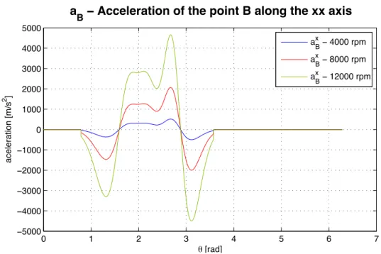
0 1 2 3 4 5 6 7 −5000 −4000 −3000 −2000 −1000 0 1000 2000 3000 4000 5000 θ [rad] aceleration [m/s 2 ]
aB − Acceleration of the point B along the xx axis
a B x − 4000 rpm a B x − 8000 rpm a B x − 12000 rpm
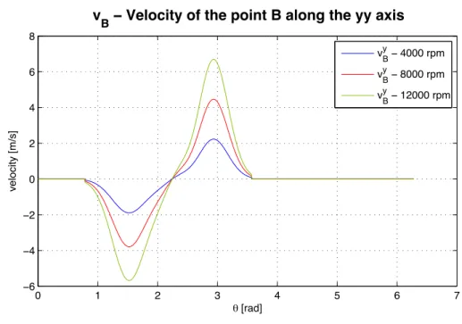
0 1 2 3 4 5 6 7 −6 −4 −2 0 2 4 6 8 θ [rad] velocity [m/s]
vB − Velocity of the point B along the yy axis
vBy − 4000 rpm vBy − 8000 rpm vBy − 12000 rpm
Figure 4.25: profile for the exhaust sub-system at various engine speeds
0 1 2 3 4 5 6 7 −1 −0.8 −0.6 −0.4 −0.2 0 0.2 0.4 0.6 0.8 1x 10 4 θ [rad] aceleration [m/s 2 ] a
B − Acceleration of the point B along the yy axis
aBy − 4000 rpm aBy − 8000 rpm aBy − 12000 rpm