Massive and Irreparable
Rotator Cuff Tears
123
Nuno Sampaio Gomes · Ladislav Kovačič
Frank Martetschläger · Giuseppe Milano
Editors
From Basic Science to
Advanced Treatments
67 © ESSKA 2020
N. Sampaio Gomes et al. (eds.), Massive and Irreparable Rotator Cuff Tears,
https://doi.org/10.1007/978-3-662-61162-3_8
Imaging of Repaired Rotator Cuff
Ricardo Sampaio, Carlos Abel Ribeiro,
and Nuno Sampaio Gomes
8.1
Introduction
Imaging of the repaired rotator cuff can be accomplished with several imaging modalities, including radiography, ultrasonography (US), computed tomography (CT), and magnetic reso-nance (MR) imaging. Usually, the imaging algo-rithm follows the same algoalgo-rithm used locally for imaging the nonrepaired cuff. Radiography remains a cornerstone of shoulder imaging and a first-line imaging modality, whether on post-op shoulders or not. In expert hands, US is an excel-lent modality to image the cuff tendons, including the repaired cuff. For small tears, US may even be better than MR imaging. Magnetic resonance imaging allows the most comprehensive assess-ment of the shoulder, including its surrounding muscles and bone structures. In particular cases, CT or MR with intraarticular contrast (CT or MR arthrography) may be used to characterize the repaired rotator cuff.
Imaging of the postoperative shoulder usu-ally begins with radiography of the shoulder. The purpose of the radiograph is not only to detect obvious osseous complications but also to iden-tify the type of surgical procedure performed and to assess the amount of metallic implanta-tion that may be present [1]. From there, usually one proceeds to MR imaging or ultrasound of the shoulder.
8.1.1 MR Imaging Protocol
Different MR imaging sequences are used for imaging follow-up of the repaired rotator cuff. There are two basic types of MR sequences: (1) short time-of-echo (TE) sequences that depict anatomy using fat as the natural contrast (T1-weighted and proton density (PD) weighted sequences) and (2) long TE sequences that depict fluid in white shades (T2-weighted and STIR sequences). On long TE (T2-weighted) sequences in musculoskeletal imaging, fat is usu-ally suppressed (FatSat) and, therefore, shown in dark shades on images (T2-weighted FatSat sequences). After intravenous paramagnetic contrast medium administration (gadolinium compounds), the T1-weighted sequences are also acquired with fat suppression (T1-weighted FatSat Gad sequences). STIR sequences natu-rally suppress fat. There are many variants of these basic sequences; some of them designed for
R. Sampaio ( )
Radiology Department, Hospital Lusíadas Porto, Porto, Portugal
C. Abel Ribeiro
Radiology Department, Hospital da Luz Arrábida, Porto, Portugal
N. Sampaio Gomes
Orthopedics Department, Hospital da Luz Arrábida, Porto, Portugal
patients with metal implants (Figs. 8.1, 8.2, 8.3,
8.4, 8.5, 8.6, 8.7, 8.8 and 8.9).
Metal of any kind (such as in screws, anchors, sutures, wires, buttons, tacks or plates) distorts the magnetic field and results in susceptibility artifacts on MR images. Different MR sequences
in different magnetic field stregths have different sensitivities to magnetic susceptibility artifacts. As rules of thumb, the susceptibility artifact increases as one goes from T1-weighted to T2-weighted sequences, fat saturation blooms the artifact, as the use of gradient-echo T2-weighted
a
c
b
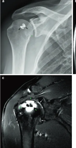
Fig. 8.1 (a–c) Metal susceptibility artifact. (a) Frontal radiograph of the shoulder. Two metal suture anchors are seen in the greater tuberosity. (b) T1-weighted coronal MR image. The suture anchors metallic artifact distorts the anatomy (black arrows). The anchors themselves are not really visualized. Subcutaneous fat is bright as is the fatty bone marrow in the marginal osteophyte in the
humeral head (green asterisk). (c) T2-weighted FatSat coronal MR image. The artifact from the suture anchors blooms, with a halo of artifactual blurring of the image around the anchors (arrow heads). Tiny amounts of fluid in the joint cavity are seen as bright spots (white arrows). Subcutaneous and bone marrow fat is suppressed and depicted in dark shades on the image
69
a b
c
e
d
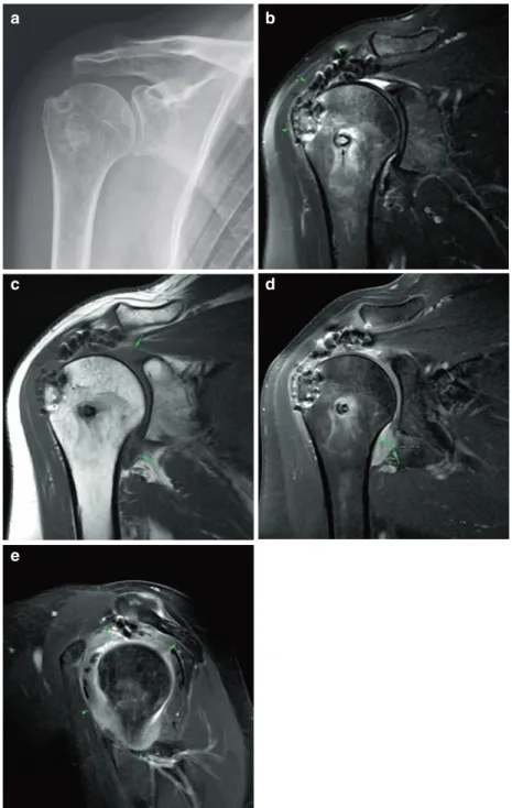
Fig. 8.2 (a–e) Nonmetal suture anchor artifact. (a) Frontal radiograph of the shoulder post supraspinatus reinsertion. The bioabsorbable suture anchor is not appre-ciated on the radiograph. There are small calcifications in the acromioumeral space. (b) T1-weighted coronal MR image. The nonmetallic anchor is readily seen with no significant artifact (arrowheads). Normal osteointegration of the anchor. (c) T2-weighted FatSat coronal MR image.
There is some artifact caused by the anchor (arrowheads) but not enough to prevent the supraspinatus tendon from being evaluated. The supraspinatus tendon looks normal. (d, e) T1-weighted axial MR images. The anchor is defined in two adjacent planes (arrowheads). Subscapularis tendinosis (white arrow): the tendon is thickened at its insertion and maybe delaminated due to subluxation of the long head of the biceps tendon
(T2∗-weighted) sequences does (Figs. 8.1, 8.6, and 8.7), and the greater the magnetic field strenght the greater de artifact. On postoperative MR images, one should be aware of the possibil-ity of metal artifact, so not to misconstrue artifact for pathology. Metal sources in bone and soft tis-sues after open or arthroscopic rotator cuff repair can be not only screws, anchors, and sutures, but
also microscopic metal particles from the surgical instruments themselves, such as guides, probes, forceps, and cutting tools (Figs. 8.6 and 8.7).
Metal alloys always result in susceptibility artifacts, although not the same amount of arti-fact is seen in the same sequence for different implant compositions. The degree of artifact in the presence of metal implants is related to the
a
c
b
Fig. 8.3 (a–c) Nonmetal suture anchor post arthroscopic repair of a Bankart lesion with bioabsorbable suture anchors. (a) T2-weighted FatSat sagittal MR image. The suture tracks are readily appreciated with normal appearance (arrowheads). (b) T2-weighted MR image, nonfat saturated.
Small dots along the anterior margin of the glenoid represent the osteointegrated bioabsorbable suture anchors (arrow-heads). (a) T1-weighted coronal MR image, same patient. One of the suture anchors is seen normally osteointegrated (arrowhead). The anatomy is otherwise normal
71
Fig. 8.4 (a–h) Supraspinatus tendon repair follow-up. (a) Frontal radiograph of the shoulder post supraspinatus reinsertion. The bioabsorbable suture anchor track is barely appreciated (arrowhead). (b) T2-weighted FatSat coronal MR image. The suture anchor is visible with mild osteolysis and edema of the surrounding bone marrow, normal for several weeks to months after surgery. There is no dislocation of the anchor (green arrowhead). The supraspinatus tendon is thickened, and its signal is very heterogeneous, also normal in the postoperative period. There is a small focus of fluid signal intensity in the artic-ular side of the tendon footprint (white arrowhead), non-specific (could be granulation tissue, a small residual communication or a small type 1 retear of the tendon). Bursitis-like signal intensity is seen in the subacromial bursal space, a normal finding for many months after sur-gery. (c) The corresponding T1-weighted coronal image. (d) T1-weighted FatSat Gad coronal image. This is a T1-weighted image with fat saturation and intravenous gadolinium. Inflammatory and granulation tissue takes up
contrast (enhances). There is granulation tissue in the small communication in the supraspinatus tendon foot-print (arrowhead). (e) T2-weighted FatSat coronal MR image, 10 months latter from image B. In the follow-up 10 months later, some loss of thickness and fissuring are seen in the supraspinatus tendon with a small bursal-side par-tial type 2 tear (arrowhead). (f) T2-weighted FatSat coro-nal MR image, 17 months later from image B. In the follow-up 17 months later, the small bursal-side partial type 2 tear (arrowhead) is better appreciated. This tear is not necessarily functionally relevant. The supraspinatus tendon is thinner than on the first postoperative MR study. (g) T2-weighted FatSat sagittal MR image, 17-months follow-up. The supraspinatus tendon is very heteroge-neous, with several small transtendinous fissures (arrow-heads), but for the most part reattached to the greater tuberosity. (h) Final frontal radiograph of the shoulder 17-months follow-up. New hyperostosis has developed in the supraspinatus footprint, as compared to the initial radiograph (a) (arrowhead)
a b
c d
quantity of metal, the particular elements of the metal alloy, the geometry of the implant, the MR acquisition parameters, and the field strength of the MR equipment. Metallic artifact is greater with ferromagnetic implants (steel, for instance) than with nonferromagnetic metal implants, such as titanium. Susceptibility to artifact increases in a linear fashion with magnetic field strength. Therefore, the artifact will be greater at 3.0 Tesla than at 1.5 Tesla and will be the least in low-field permanent magnets (0.3 Tesla, for instance), such as in dedicated extremity MR installations.
Nonmetal implants (such as bioabsorbable interference screws or suture anchors) do not
cause susceptibility artifacts per se, but suscep-tibility artifacts may still be present due to the microscopic metal particles from the surgical instrumentation (Figs. 8.2 and 8.3).
8.1.2 Normal Cuff Repair
Surgery intended to repair the shoulder rotator cuff will change the anatomy in several differ-ent ways. The tendon may be reinserted into the bone; the tendon may be cut and inserted somewhere else as in bicipital tenodesis or in cuff tendon transposition, or may be cut off
e
g h
f
73
altogether as in bicipital tenotomy; the bony environment to the cuff may be modified as in the acromioplasty procedure; enthesophytes or osteophytes may be excised, and muscle may
the cut open and then sutured, as in transdeltoid open surgery [2, 3].
Arthroscopic surgery results in different changes from the ones seen after open surgery,
a b
c d
Fig. 8.5 (a–d) Subscapularis tendon repair follow-up. (a) Frontal radiograph of the shoulder post subscapularis ten-don reinsertion. There are no metal implants. (b) Pre-op T2∗-weighted axial MR image. There is a full-thickness subscapularis tendon tear (arrowheads) with moderate myotendinous retraction (asterisk). (b) Postoperative PD-weighted axial MR image with intraarticular contrast (MR arthrography). The subscapularis tendon has been successfully reattached and the subscapularis
myotendi-nous junction has now a normal position (asterisk). One of the nonmetallic suture anchors is also seen (arrowhead). (c) Postoperative T1-weighted FatSat coronal MR image with intraarticular contrast (MR arthrography), same day. There are small partial bursal-sided tears in the undersur-face of the supraspinatus tendon (white arrowhead), apparently new as compared to the preoperative MR study. One of the suture anchors is seen normally osteointegrated
a
b
c
d e
f g
Fig. 8.6 (a–g) Cuff repair follow-up, acromioplasty. (a) Preoperative T2-weighted FatSat coronal MR image. There is a full-thickness tear of the supraspinatus tendon with moderate retraction of the tendon (Patte stage 2). The tendon tear was also demonstrated on ultrasound (Insert
b). (c) Preoperative T2-weighted sagittal MR image.
Normal thickness of the acromion. (d) Frontal radiograph of the shoulder post supraspinatus tendon repair. There are two metal suture anchors and a nonmetal anchor (arrowhead). (e) Postoperative T2-weighted FatSat coro-nal MR image. The supraspinatus tendon has been
par-tially reattached to the humerus. The tendon is not as thick as it would be if fully reattached. Black arrowhead: non-metal suture anchor. (f) Postoperative T2∗-weighted axial MR image. Open surgery with susceptibility artifact foci in the soft tissues in the deltoid area (arrowheads) from surgical instrumentation (no metal is seen in the soft tis-sues on the same day radiograph—Fig. d). (g) Preoperative T2-weighted sagittal MR image. Acromioplasty has been performed. The undersurface of the acromion has been shaved and the thickness of the acromion is reduced as compared to the preoperative images
75
a b
c
e
d
Fig. 8.7 (a–e) Cuff repair follow-up. Adhesive capsulitis. A Frontal radiograph of the shoulder post cuff repair. No metal implants are seen. A postoperative trough is present in the supraspinatus footprint. There has been acromio-plasty. (b) Postoperative T2-weighted FatSat coronal MR image. There is extensive susceptibility artifact in the supraspinatus tendon despite the fact that no metal particles are seen in the tendon on the same day radiograph (a). The supraspinatus tendon appears to be reattached to the tuber-osity. The tip of a suture anchor is visible (black arrow). (c) Postoperative T1-weighted coronal MR image. The
capsu-lar axilcapsu-lary recess appears thickened, and there is also apparent capsulosinovial thickening or fluid in the superior recess (arrows). Note the susceptibility artifact in the supra-spinatus tendon. (d) Postoperative T1-weighted FatSat coronal MR image with intravenous gadolinium. (e) Postoperative T1-weighted FatSat sagittal MR image with intravenous gadolinium. There is capsular enhancement and thickening and no fluid in the joint, consistent with adhesive capsulitis. The capsular fibroblastic reaction is cir-cumferential although most prominent in the axillary and subcoracoid recesses of the glenohumeral joint
and certain complications are particular to the type of surgery performed, such as the deltoid dehiscence that may occur after open surgery. All of these changes are amenable to imaging inves-tigation, particularly, MR imaging (Figs. 8.4, 8.5,
8.6, 8.7, 8.8, and 8.9).
Surgery may fail for any number of reasons, or the patient’s symptoms may fail to resolve. Up to 25% of patients remain symptomatic after surgi-cal repair of the rotator cuff [4]. Imaging is usu-ally warranted to study these patients and when that happens, MR is usually called upon to image
a
c
b
Fig. 8.8 (a–c) Cuff repair follow-up. Chronic deltoid dehiscence. (a) Postoperative T1-weighted coronal MR image. (b) Postoperative T1-weighted axial MR image. There has been detachment of the deltoid muscle from the acromion (arrows) with atrophy and fatty degeneration of the acromial belly of the deltoid muscle (arrows). For
comparison, see the clavicular portion of the deltoid (asterisk) or the subscapularis muscle belly (double aster-isk). (c) Different patient, a frontal radiograph of the shoulder shows heterotopic ossification of the deltoid muscle origin in the acromion, post open surgical repair of the rotator cuff
77
the shoulder [4–6]. On MR imaging, the repaired tendon will show heterogeneous signal intensity, from postsurgical changes, healing response, and preexisting tendinopathy (Fig. 8.4). These signal changes are most conspicuous on short TE MR
images (such as T1-weighted and PD-weighted images). They are less conspicuous on long TE images (such as on T2-weighted images). The tendon will usually be thicker than a normal tendon, but not always. If the quality of the
pre-a b
c d
Fig. 8.9 (a–d) Cuff repair follow-up. Long head of the biceps tenodesis. (a) Frontal radiograph of the shoulder shows a metallic anchor or interference screw in the humeral metaphysis. (b) T2-weighted sagittal MR image at the level of the spine of the scapula. There is massive atrophy and fatty degeneration of the supraspinatus and infraspinatus muscles (Thomazeau Stage 3), most likely beyond repair (asterisks). (c) Postoperative T2-weighted
FatSat coronal MR image. Complete tear of the supraspi-natus tendon with massive retraction of the tendon (arrow). The repair of the supraspinatus tendon was either not attempted or failed. (d) T1-weighted axial MR image. The screw was used to fix the long head of the biceps ten-don into the biceps tenten-don gutter (biceps tenodesis). There is no apparent adverse reaction to the implant
op tendon edges is poor, or the tendon is asym-metrically retracted, it might be only partially reattached to the bone, and the final result will be a tendon less thick or equal in thickness to a normal tendon (Fig. 8.6). A repaired tendon thinner or equal in thickness to a normal tendon has been either partially reinserted or, if initially fully reinserted, has suffered a partial retear. The repaired tendon, if fully reattached, is always thicker than a normal tendon and usually thicker than the preoperative tendon (Figs. 8.4 and 8.5). The thickness of the tendon is a much more reli-able indicator of pathology than signal changes on MR imaging.
On long TE MR images (T2-weigheted images), fluid within the tendon usually indi-cates tendinous communication, either remnant communication or retear of the tendon. After sur-gical repair of a cuff tear, the tear is not always completely sealed, and small transtendinous communications may persist. They are easily depicted on MR arthrography and US and may be less conspicuous on conventional MR studies. However, they may not be clinically relevant. Small residual defects or retears (<1 cm) of the rotator cuff are not necessarily associated with clinical symptoms. Partial and even full-thick-ness tears are common in asymptomatic patients after surgery. Likewise, subacromial bursitis-like MR abnormalities are almost always seen after rotator cuff repair, even in patients with-out residual complaints (Fig. 8.4). Fluid in the subacromial bursa may persist for several years after rotator cuff repair and appear to be clini-cally irrelevant [1, 4].
In practice, tendon repairs are often thinner than a normal tendon. Interestingly, cuff repair footprint coverage may improve by the end of the first postoperative year. The appearance of the repaired rotator cuff on MR imaging shows con-siderable variability in the first postoperative year and does not correlate to outcome. The tendon appearance often becomes more like normal ten-don by 1 year after surgery [7]. Improvement in signal changes, when it occurs, generally devel-ops between 3 and 12 months.
To avoid magnetic susceptibility artifacts at MR imaging, T2-weighted inversion recovery
(STIR) imaging may be used instead of fat satu-ration, and fast spin-echo sequences may be used instead of conventional spin-echo sequences or gradient-echo sequences. The technical param-eters of the MR sequences may have to be modified to minimize metallic artifact or some sequences may have to be substituted for others. There are specially designed sequences for metal MR imaging, but they are not available in all MR scanners.
MR arthrography may also be used, instead of conventional MR imaging (Fig. 8.5). The advantages of MR arthrography include better definition of the rotator cuff articular side, more accurate assessment of capsule volume and delin-eation of labral ligamentous structures, and aid in the differentiation of partial- and full-thickness tears [6]. However, contrast accumulation within the subacromial bursa (a characteristic sign for a full-thickness tear in nonoperated shoulders) has substantially less impact in patients after sur-gery because the rotator cuff does not need to be watertight to be functional [4].
Ultrasound is able to look at the entire distal cuff, provided that the patient is able to freely move the shoulder into the positions required to access the supraspinatus and the subscapularis tendons (extension, adduction and external rota-tion). Patients unable to move the shoulder, for instance patients with adhesive capsulitis, are not good candidates for US of the repaired cuff. Otherwise, US can show suture dehiscence, tendon avulsion, or retear of the repaired ten-don as well as adverse reactions to intratendi-nous sutures [8, 9]. A subdeltoid bursal effusion representing residual arthroscopic fluid and/or hematoma may persist for several months after surgery.
Ultrasound is usually requested to detect suture failure or retear of a repaired cuff ten-don. Although the repaired tendons demonstrate altered echogenicity and thickness, in compari-son to a normal tendon, US can accurately pre-dict the localization and extent of a cuff tear, with a comparable accuracy to MR imaging [10]. Ultrasound can be used to serially monitor the postoperative cuff changes after surgical repair [9]. Ultrasound is cheaper than MR imaging and
79
more patient friendly and a lot faster, but counter-intuitively may be less available, due to the long learning curve it takes the operator to become proficient in shoulder US.
Ultrasound is not so good as an imaging method to look at intraosseous adverse reac-tions related to suture anchors, tacks or screws, or bone vascular changes. A combination of radiography and US may overcome the limita-tions of each of the methods, but glenohumeral chondral and labral pathology, bone marrow, complex ganglion cysts, and muscle pathology remain best studied with MR imaging. If a phy-sician with similar experience with MR and US is available, the preference for either one of these tests should not be based on the accuracy of the imaging modality, but rather on patient toler-ance, cost, and the importance of detecting non-rotator cuff pathology, such as labral, capsular, or bone lesions.
Mild superior subluxation of the humeral head may persist after open or arthroscopic cuff repair, maybe due to capsular tightening, scarring, cuff atrophy, or bursectomy, and can be appreciated on radiographs of the shoulder. Changes to the subacromial bursa and to the acromion and lat-eral end of the clavicle are easier to evaluate with MR imaging. Postacromioplasty acromial changes are surprisingly hard to see on radio-graphs (Fig. 8.6).
8.1.3 Failed Cuff Repair and Complications
A number of events may cause a repaired cuff to fail. The tendon may suffer a repeat tear (for instance, during over vigorous physical therapy), or the anchor or suture may fail, and the tendon may detach from the bone. Despite anatomi-cally correct repair, pain may persist, or a second lesion may develop. Complications may arise at the coracoacromial arch or the deltoid incision. General adverse events such as adhesive capsuli-tis or infection may arise. When pain or disability occurs after rotator cuff surgery, postoperative imaging is frequently performed, usually MR imaging [1].
8.1.4 Retear of the Repaired Cuff
Retear of a previously repaired rotator cuff ten-don is relatively common and does not necessar-ily compromise functional outcome or patient satisfaction [7]. Two patterns of retear have been described: in type 1 retear, the tendon fails at the tendon-bone interface, and in type 2 retear, the cuff failure happens medially, about the myoten-dinous junction 1.5–2 cm medial to the tendon insertion, with the remnant cuff still attached to the humeral tuberosity [11]. Type 1 tears tend to occur earlier in the postoperative period and may result from failure of the tendon-to-bone fixation. Type 2 tears tend to occur later in the postopera-tive period and may be related to progression of tendon disease, impaired vascularity, or increased tension after reattachment of the tendon (Fig. 8.4).
Magnetic resonance imaging will allow for the detection of the cuff retear as well as its stag-ing and classification. On MR imagstag-ing, a recur-rent tendon tear will be seen as a fluid-filled defect within or across the tendon on long TE (T2-weighted) images. Secondary signs of ten-don retear include tenten-don retraction and loss of tendon thickness. It may be difficult to differ-entiate tendinosis, granulation tissue, and heal-ing response from a partial retear although the healing response will evolve over time, with the signal intensity expected to decrease on long TE MR images for about one year [7]. Full thickness retears are easier to demonstrate on MR images. The presence of a recurrent tear is not necessar-ily symptomatic, but the size of the tear may be correlated with the development of symptoms [1] (Figs. 8.4, 8.5, and 8.9).
Ultrasound will depict type 1 retears, but may fail to show type 2 retears, particularly if the patient is unable to fully extend, adduct, and externally rotate the shoulder.
8.1.5 Suprascapular, Axillary Nerve Palsy
Muscle edema when the muscle is anchored in the humerus usually reflects acute muscle dener-vation or myositis. Muscle denerdener-vation may
occur for a variety of reasons, the two most com-mon being neuritis (as in the Parsonage-Turner syndrome) and nerve entrapment or injury. Nerve entrapment and nerve injury may occur during and after surgery. Long TE MR fat-suppressed images (T2-weighted FatSat or STIR images) are very sensitive to muscle edema, not only detecting acute signs of denervation (days or weeks after the nerve lesion) but also mapping the involved muscles, so the involved nerve is identified [12]. In the postoperative shoulder, localized edema or soft-tissue reaction may cause enough pressure on a nerve (suprascapular nerve, for instance) to result in acute denervation in that particular nerve territory. Intraoperative axillary nerve injury will result in teres minor and del-toid muscle denervation, and MR is well suited to diagnose the muscle edema associated with such instances of muscle denervation.
Chronic muscle denervation will result in muscle atrophy and fat infiltration, and both phenomena are also very well depicted on MR images (Fig. 8.9).
8.1.6 Postoperative Bursitis,
Synovitis, Adhesive Capsulitis, Scarring
Postoperative bursitis is a relatively frequent finding in patients with persistent or recurrent pain. Inflammation of the bursae is best depicted on T1-weighted fat-saturated MR images with gadolinium. Care should be taken not to overcall subacromial bursitis, as bursal signal abnormali-ties are very common in asymptomatic patients. These bursitis-like changes may persist for a long time after surgery (up to 4–5 years) [4].
Adhesive capsulitis may be a cause of persis-tent symptoms after cuff repair. This complication usually occurs shortly after cuff repair. Adhesive capsulitis may not be recognized on standard MR images as the capsulosinovial thickening may be subtle and the inflamed synovium may be diffi-cult to tell from joint fluid on fat- suppressed long TE MR images, aside from the postoperative changes in the rotator cuff interval and in the sub-coracoid fat triangle. MR T1-weighted imaging
with intravenous contrast medium (gadolinium) is better able to show thickening and enhance-ment of the joint capsule and synovial membrane along with the tightness of the joint cavity that characterizes adhesive capsulitis (Fig. 8.7).
Patients after rotator cuff repair may have per-sistent pain and dysfunction caused by exuberant postoperative reaction and scar formation. This reaction may involve the subacromial area, the joint capsule, the tendons, and adjacent soft tis-sues. Scar tissue is made up of collagen and show up on MR images as bulky masses or bands of low-signal intensity tissue on short and long TE images, reflecting dense fibrotic adhesions and even calcified or ossified scar tissue. Myositis ossificans and heterotopic ossification may occur in muscle incisions and tracts, particularly in the deltoid muscle (Fig. 8.8c).
Tendon dystrophic calcifications are a sec-ondary manifestation of tendon degeneration. Calcifications are easier to detect on gradient- echo (T2∗) MR images because these imagens
are more sensitive to magnetic susceptibility. Unfortunately, this increased sensitivity to cal-cifications of T2∗ images also make them more
prone to artifacts due to metal implants and debris. On ultrasound, sutures and microcalcifi-cations can be difficult to tell apart. On radiogra-phy, only calcifications that are not superimposed on the humeral head are readily visualized.
8.1.7 Infection, Loose Bodies
A significant fluid collection about the joint without focal tendon discontinuity suggests the presence of complication, including infection, perisutural inflammation, synovitis associated with loose bodies, or loose surgical implants. Intravenous paramagnetic contrast medium administration greatly enhances the ability of MR to show inflammatory tissue and fluid collec-tions. Bone marrow edema and periarticular and subchondral erosions are findings better depicted on MR imaging. Imaging (usually ultrasound) can also serve as a guide to direct a needle to an optimal site for aspiration of joint fluid, should the possibility of a septic joint be considered.
81 8.1.8 Deltoid Dehiscence
Open cuff repair usually involves an incision through the acromial part of the deltoid muscle. This incision is closed on surgery completion, and the muscle is reattached to the acromion, but the suture may fail, or the muscle may tear along the incision or acromial reattachment and result in deltoid dehiscence. MR imaging can show a fluid-filled defect within the muscle with or with-out retraction of the muscle. If the dehiscence is chronic, muscle atrophy and fatty degeneration may be present [1] (Fig. 8.8).
8.1.9 Implant (Suture Anchors, Tacks, Screws) Complications
Surgical implants used to repair the cuff and facilitate the soft tissue-to-bone repair, such as suture anchors and screws, can be either made up of metal alloys or nonmetal bioabsorbable materials (bioabsorbable polymers and calcium ceramics) [13]. They can fail or complicate by several mechanisms, such as loosening or migration, foreign body reaction, cyst forma-tion or infecforma-tion, impingement upon surround-ing bone or soft tissue structures, fracture of the host bone, loose intraarticular foreign bodies, synovitis, or cartilage damage [13–16]. Among these complications, osteolysis and cyst forma-tion, enlargement of drill holes, loosening and anchor pull-out, and suture break away from the anchor are probably the most important in rota-tor cuff repair.
Nonmetal bioabsorbable implants allow for decreased artifact during MR imaging, although still some artifacts may be seen (Figs. 8.2 and
8.3). Resorption of the anchor is the desirable course for bioabsorbable implants, which have different degradation profiles and are, over time, replaced by bone or calcified fibrosis within the screw track. However, exposure to the debris of absorbable anchors in the joint can cause syno-vitis and pain. MR imaging is able to demon-strate the implant location and its surrounding environment as well potential complications
related to the implant, such as cyst formation, track enlargement, implant displacement, or infection [1, 15, 17].
Metallic implants are easily spotted with radi-ography and the amount of susceptibility artifact they create may render them invisible on MR images. Worse, the artifact creates a blind zone around the implant that may prevent complica-tions in the vicinity of the implant from being visualized (Fig. 8.1). Metallic implants create their own risks in the MR environment, such as overheating of the implant and implant-induced internal burns. Certain metal compositions (steel, for instance) are deflected by the magnetic field and may be displaced by simply placing the patient inside the magnet of the MR machine.
New not bioabsorbable implants (such as polyetheretherketone or PEEK) are radiolu-cent and, therefore, not visible on radiographs. Similar to metallic implants, they do not resorb, but similar to bioabsorbable implants they are visible on MR imaging, and their susceptibility artifact profile renders them accessible to MR imaging interrogation.
8.1.10 Other Causes of Pain After Cuff Repair
In patients with failed rotator cuff surgery, it is possible that other pathologies are generating pain and may be the primary source of symp-toms, rather than the rotator cuff [18].
Long head of biceps tendon subluxation is common in patients with chronic rotator cuff tear. If not repaired at the time of surgery, biceps tendon subluxation may persist after surgery. Biceps tendon subluxation may also develop de novo in a patient already submitted to cuff repair. Superior labrum anterior poste-rior (SLAP) lesions may also account for the patient’s symptoms.
US is ideally suited to diagnose biceps tendon subluxation due to its dynamic nature. If the ten-don spontaneously reduces in the neutral position of the shoulder, MR imaging may miss the biceps tendon subluxation.
8.2
Conclusion
The imaging assessment of patients who have had rotator cuff surgery includes a radiographic examination followed by either MR imaging (sometimes MR arthrography) when a compre-hensive shoulder evaluation is desired, or ultra-sound when targeted to identifying rotator cuff recurrent tears. Knowledge of common surgical procedures and expected postoperative findings on various imaging techniques and potential complications are important for the imaging eval-uation of the shoulder after rotator cuff repair.
References
1. Thakkar RS, Thakkar SC, Srikumaran U, McFarland EG, Fayad LM. Complications of rotator cuff sur-gery—the role of post-operative imaging in patient care. Br J Radiol. 2014;87:20130630–12.
2. MD LWB, MD CW, MD CP, MD TF. Postoperative shoulder magnetic resonance imaging. Magn Reson Imaging Clin N Am. 2012;20:313–25.
3. Beltran LS, Bencardino JT, Steinbach LS. Postoperative MRI of the shoulder. J Magn Reson Imaging. 2014;40:1280–97.
4. Zanetti M, Jost B, Hodler J, Gerber C. MR imaging after rotator cuff repair: full-thickness defects and bursitis-like subacromial abnormalities in asymptom-atic subjects. Skeletal Radiol. 2000;29:314–9. 5. Gusmer PB, Potter HG, Donovan WD, O’Brien
SJ. MR imaging of the shoulder after rotator cuff repair. Am J Roentgenol. 1997;168:559–63.
6. Mohana-Borges AVR, Chung CB, Resnick D. MR imaging and MR arthrography of the postoperative shoulder: spectrum of normal and abnormal findings. Radiographics. 2004;24:69–85.
7. Crim J, Burks R, Manaster BJ, Hanrahan C, Hung M, Greis P. Temporal evolution of MRI findings after arthroscopic rotator cuff repair. AJR Am J Roentgenol. 2010;195:1361–6.
8. de Beer J. Journal AKSO, 2009 Sonographic evalua-tion of the arthroscopically repaired rotator cuff. sci-elo.org.za
9. Yoo HJ, Choi J-Y, Hong SH, Kang Y, Park J, Kim SH, Kang HS. Assessment of the postoperative appear-ance of the rotator cuff tendon using serial sonogra-phy after arthroscopic repair of a rotator cuff tear. J Ultrasound Med. 2015;34:1183–90.
10. Lee SC, Williams D, Endo Y. The repaired rota-tor cuff: mri and ultrasound evaluation. Curr Rev Musculoskelet Med. 2018;11:1–10.
11. Bedeir YH, Schumaier AP, Abu-Sheasha G, Grawe BM. Type 2 retear after arthroscopic single-row, double-row and suture bridge rotator cuff repair: a systematic review. Eur J Orthop Surg Traumatol. 2018;19:1–10.
12. Kim S-J, Hong SH, Jun WS, Choi J-Y, Myung JS, Jacobson JA, Lee JW, Choi J-A, Kang HS. MR imag-ing mappimag-ing of skeletal muscle denervation in entrap-ment and compressive neuropathies. Radiographics. 2011;31:319–32.
13. Dhawan A, Ghodadra N, Karas V, Salata MJ, Cole BJ. Complications of bioabsorbable suture anchors in the shoulder. Am J Sports Med. 2012;40:1424–30. 14. Willemot L, Elfadalli R, Jaspars KC, Ahw MH, Peeters
J, Jansen N, Declerq G, Verborgt O. Radiological and clinical outcome of arthroscopic labral repair with all- suture anchors. Acta Orthop Belg. 2016;82:174–8. 15. Kim SH, Oh JH, Lee O-S, Lee H-R, Hargens
AR. Postoperative imaging of bioabsorbable anchors in rotator cuff repair. Am J Sports Med. 2014;42:552–7.
16. Take Y, Yoneda M, Hayashida K, Nakagawa S, Mizuno N. Enlargement of drill holes after use of a biodegradable suture anchor: quantitative study on consecutive postoperative radiographs. Arthroscopy. 2008;24:251–7.
17. Stein T, Mehling AP, Reck C, Buckup J, Efe T, Hoffmann R, Jäger A, Welsch F. MRI assessment of the structural labrum integrity after Bankart repair using knotless bio-anchors. Knee Surg Sports Traumatol Arthrosc. 2011;19:1771–9.
18. Pierce JL, Nacey NC, Jones S, Rierson D, Etier B, Brockmeier S, Anderson MW. Postoperative shoul-der imaging: rotator cuff, labrum, and biceps tendon. Radiographics. 2016;36:1648–71.