Repairing of an Engine Block Through the Cold Gas Dynamic Spray Technology
Antonello Astaritaa, Fabrizio Coticellia, Umberto Priscoa*
Received: February 10, 2016; Revised: June 20, 2016; Accepted: August 11, 2016
In the modern automotive industry, the maintenance of the vehicle during its life cycle is increasing in importance due to both economical and environmental considerations. A new frontier is the reparation of large parts, originally made by fusion, by the addition of material. The standard technique in the
ield is the use of TIG welding, but in the last few years Cold Dynamic Gas Spray (CDGS) has started to show many promises in supplanting TIG repairs. The main advantage of CDGS is the absence of
thermal stresses in the repaired zone with the elimination of thermal distension treatment of the part.
In this paper we study the use of CDGS to repair wear damage on a commercial aluminium engine block in comparison with the standard repair procedure with TIG. The result obtained shows that CDGS is an efective technology for industrial-level repair.
Keywords: Cold Spray, Aluminum, Engine Block Repairing, Welding.
* e-mail: [email protected]
1. Introduction
During the last decade Cold Gas Dynamic Spray (hereinafter called CGDS or simply Cold Spray) has been
the object of great interest from both research community and industry, with several research papers, patents, and books published on this topic1,2. Nowadays cold spray is no more
an experimental technology conined to the laboratory but has proven its ability to compete in the commercial ield with
older technologies, with special regards to the production of metallic coatings and the repair of damaged components3,4.
CGDS is an additive manufacturing process in which a
layer is deposited by means of high velocity impacts of metallic particles carried by a supersonic gas. Unlike other
deposition technologies, in CGDS the bonding between the
particles and the substrate is made at a comparatively low temperature, and as result the particles do not undergo phase changes5,6. Through the use of a converging/diverging nozzle
(De Laval nozzle) a heated gas is pushed into a supersonic laminar low. The metallic particles are dispersed into this low and propelled to supersonic velocities, usually in the
range between 500 and 1000 m/s. When the particle hit the substrate the high kinetic energy causes a phenomenon of macroscopic plastic deformation that embeds the particle on the substrate while preserving its crystalline structure7. For
the bonding to succeed it is necessary that the kinetic energy of the single particle is higher than a threshold value8,9. The
velocity at which the bonding is achieved is called critical velocity and it is function of the particle size and distribution as well as the substrate material. The coatings exhibit high density and conductivity, good corrosion resistance and high hardness, due to the cold worked microstructure10.
Due to the absence of thermal stresses during the deposition process, CGDS results a repair technique suitable for a wide
range of components, like turbine blades, pistons, cylinders,
valves, rings, bearing components, pump elements. Some
recent studies investigated this application for light alloy11,12,
titanium13 and for cast iron14 components, which are not
repairable with the usual technologies. The opportunity of using cold spraying for both additive manufacturing and part repair has not been missed by the industry. There are many patents, both approved and proposed, which take advantage of the comparative lack of heating for producing coatings with a determined phase structure that would not be obtainable with conventional hot methods.
Aluminum-based alloys engine blocks can undergo several types of damages. Sometimes, the compression in the cylinder
can cause a leak though the gasket; a blown head gasket can occur in case of severe damage. The use of aluminum rather than iron cylinder heads has aggravated this problem, due to the greater thermal expansion of aluminum alloys and the subsequent greater stress transferred on the head gasket. In addition to the previous one, leaks due to problems occurring in the cooling system can take place. In this case, stray voltage through the coolant can produce an electrolytic action that can determine considerable block damage in a short period of time. The resulting damages can be erosion, pitting or cracks, up to the failure of the cylinder block. For these reasons, the wear and corrosion resistance are among the most important characteristics required from an engine block.
Usually, the damaged areas of the head or engine block are resurfaced if it is needed to restore the correct geometry in order to ensue the coupling with other parts, e.g. restoring
the latness of a damaged head engine so that the head gasket
could seal properly. However, the engine block must be replaced in case of extensive damage.
a Dept. of Chemical, Materials and Industrial Production Engineering, University of Napoli Federico II,
Considering that the replacement of these parts is very
expensive, there is an increasing trend to develop repair processes capable of restoring the materials to an acceptable level of structural integrity and functionality. This topic is the focal points of the present paper.
Common techniques in use today to repair damages
in large components are welding15 and bonding16. Welding
entails some disadvantages; in particular, it causes high tensile residual stresses and produces alterations of the
base material in the repaired zone. These efects deterirate the performance of the component, so that a post-weld heat treatment (PWHT) is usually required to relieve the residual
stresses and restore the properties of the base material. In
large components, PWHT can produce high distortions and usually requires long time. The use of CGDS, as an
alternative to welding, prevents the formation of tensile residual stresses and alteration of the base metal; for these reasons, heat treatments after the repair are not required. This allows reduction of costs and avoids the risk of distortions
that could compromise the reuse of the component. CGDS
could also be used to repair/restore some areas of those components that cannot be repaired by welding. For example, it is not possible to repair thin walls with welding, due to the fact that the induced thermal stresses would severely modify the local microstructure compromising the properties of the base material.
The present work studies the feasibility of GDCS as a
repair technique for aluminum engine blocks with particular focus on the microstructure, hardness and corrosion resistance of the restored zones. A comparison of the results
obtained using welding and GDCS as repair technique was carried out. To this aim, artiicial damages were produced
on an aluminum engine block through machining. These
damages were then repaired using both cold spray and TIG
welding. The following investigations were carried out on both the repaired samples: metallographic observations,
micro-hardness tests on the cross sections of the repair, and
potentiodynamic polarization measurements to investigate the corrosion resistance.
2. Experimental
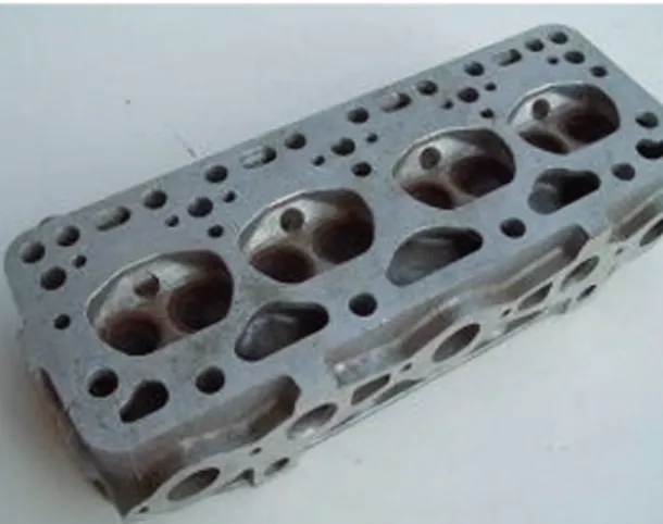
A commercial FIAT engine block was used for the
experiments, Figure 1. Supericial damages were induced on
the engine block through machining to reproduce possible damages that can occur during service. The engine block is made of A380 aluminum die casting alloy17; the chemical
composition of this alloy is reported in Table 1. In particular,
six diferent damages were produced: three were repaired
through welding and three through cold spray. The samples to be repaired were cut from the engine block through hacksaw.
A sample repaired using TIG welding is shown in Figure
2, with a section of the welded repair machined to obtain a
lat surface. Before the welding, the sample was preheated
Figure 1: Engine block used in the experimentation.
at 100 °C. TIG welding was performed under the following parameters: direct current straight polarity, 100-130 A; voltage, 11 V; welding speed, 100-140 mm/min and argon low rate, 8 LPM. The temperature was controlled after every pass
with a thermocouple to limit the base metal alterations. The
chosen iller metal was an AA4047 in form of wire, widely
used in industry for repairing worn surfaces of hydraulic components, see Table 1. After welding, the sample was protected with mineral wool, to reduce the cooling rate and to avoid an excessive alteration of the base metal.
A sample repaired by using CGDS is shown in Figure 3. Before the CGDS a grit-blasting was carried out on
the sample to improve the adhesion of the coating on the substrate material. A commercial white corundum grit of
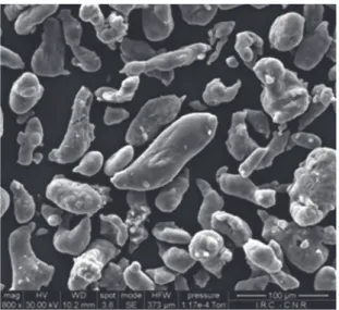
0.6-0.7-mm diameter was used. The blasting pressure was 0.6 MPa. An Al-12% Si powder, with a composition very similar to the same Al-Si alloy used in the TIG process, was
chosen for the cold spray repair, see Table 1. The powder is characterized by a mean particle diameter of 40 microns. A
SEM micrograph of the powder used is shown in Figure 4. The powder was deposited using a low pressure Dymet
413 equipment, Figure 5, with nitrogen as carrier gas. The spray conditions were the following: the propellant gas was
preheated to about 1000 °C, the gas pressure was chosen equal to 2 MPa, the spray distance was ixed in 40 mm, the particles velocity was ixed at 600 m/s and the transverse
speed of the gun was chosen equal to 0.01 m/s.
The specimens for the metallographic observations were cut from the cross section of the repaired samples to observe the microstructure of the repairing and of the base material.
For the optical and SEM observations, the specimens were
mounted in epoxy conductive resin and polished to mirror
like inishing using standard procedures. In order to reveal
the microstructure, the specimens have been etched by
Table 1: Composition of the used alloys (all values are percentage by weight).
Si Fe Cu Mg Mn Ni Zn Sn Others Aluminum
A380 Al-Si alloy 7.8 1.5 3.2 0.1 0.5 0.5 3 0.2 0.40 balance
AA4047 Filler metal 12 0.5 0.3 0.1 0.1 0.03 balance
Al-12% Si powder 12 0.3 0.1 0.1 balance
Figure 2: Macrograph of a sample repaired through TIG welding.
Figure 3: Macrograph of a sample repaired through CGDS; the red
circle highlights the repaired zone.
Figure 4: SEM micrograph of the powders used for the cold spray
repairing.
Figure 5: Low pressure Dymet equipment used for the spraying
process.
a Hitachi TM 3000 scanning electron microscope, optical observations with a Leica MM6 metallographic microscope.
Micro hardness measurements were carried out, following the ASTM E 384 standard, by using a DAT equipment with a Vickers indenter and a load of 100 g. Micro hardness has
been measured not only on the repaired areas but also on the base material next to the welded section, to better understand the changes caused by the welded process on the material properties of the engine block.
The corrosion behavior of the repairs was investigated through potentiodynamic polarizations carried out on the top surface of the repairs. The area to be tested was degreased and
polished in accordance to the ASTM standards. Measurements were carried out using a potentiostat (Biologic SP150) and a conventional electrochemical cell. A three-electrode coniguration was used in this study, and an Ag/AgCl3 MKCl and Pt were used as the reference and the auxiliary electrode electrodes, respectively. Potentiodynamic polarizations have been carried out, after monitoring the Open Circuit Potential (OCP) for 1 h, in the range from −100 mV vs OCP up to 1000 mV vs Ag/AgCl reference electrode at scan rate of 0.5 mV/s. Immersion tests in NaCl 3.5%wt solution were carried
out to further evaluate the corrosion behavior of the repairs.
3. Results and Discussion
Figure 6 shows the cross section of a cold spray repair. As
expected the aluminum substrate is not afected by the cold
spray process, even in the bonding zone the base material
preserve the initial microstructure. This initial solidiied
morphology consists of large dendrite grains, which is a typical structure obtained by casting at higher superheating
in absence of subsequent grain reinement processes. From Figure 7, which shows a SEM micrograph of the
repair cross section, it is possible to observe that the cold spray coating is quite compact and free from porosity.
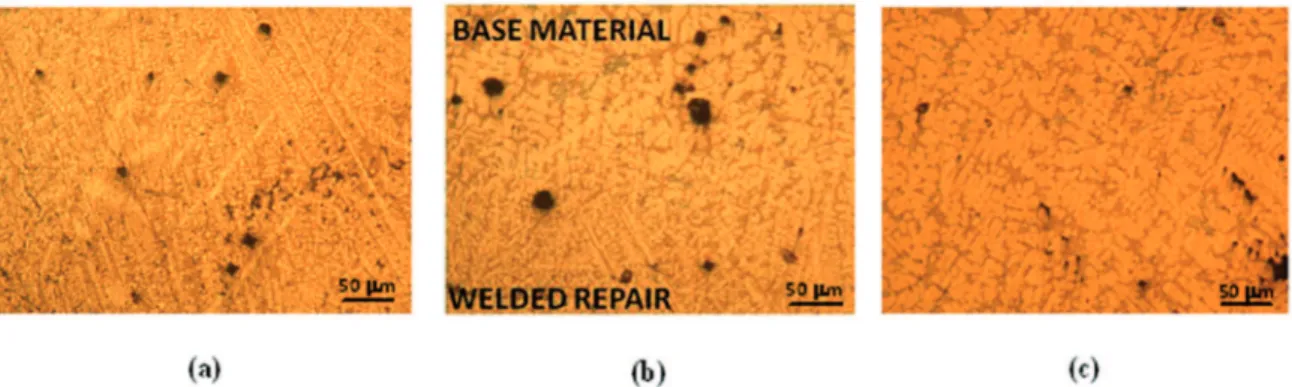
Concerning the TIG repair detailed microstructural
Figure 6: Cross section macrograph of the cold spray repair.
Figure 7: SEM micrographs of the cross section of the cold spray
repair.
Figure 8: (a) Microstructure observed in the cross section of the welded repair; (b) microstructure of the welded repair near to the base material; (c) micrograph of the base material near to the repair.
directions of the heat low because the lamellae nucleate
and grow up along this direction. The microstructure of the
base material is coarser; in Figure 8(b) is clearly evident the
interface between the base material and the welded repair. The substrate retains the initial microstructure also in this
case; this suggests that the repairing method (described in the previous section) was efective in preserving the properties of the base material of the engine block. It is very diicult to identify the heat afected zone; in fact such a zone is not
visible in the reported micrographs.
The polarization curves are reported in Figure 9. It is clear that the corrosion potential value of the base material is more positive than that of cold spray repair. Thus, the corrosion of the cold spray repair can take place in preference to the corrosion of base material. Furthermore, it is possible to assess from Figure 9 that the welding repair showed an electrochemical
behavior similar to the one of the base material while the OCP
potential of the cold spray repair is noticeably lower than the previous ones. This result suggests an anodic behavior of the cold spray repaired zone with respect to the material of the engine block8. The general trend of the curve is similar for
all the three samples under investigation.
Photographs of the top surface of the specimens after the immersion test are reported in Figure 10 (welded repair) and 11 (cold spray repair). In particular, in both cases it is
possible to observe the occurrence of classical pitting8,13. The
cold spray repair shows a better behavior with respect to the welded repair, in particular very few pits are appreciable.
Lastly the results of the microhardness measurements are
reported and discussed. An image of the indentation carried out in the cold sprayed repair is reported in Figure 12. The regular shape of the indentation is a clear indication that the deposited material is isotropic. Indeed, it is well known the relationships between the material anisotropy and the resultant indentation shape18. In particular, it was experimentally observed an increase
of the distortion of the indentation with the anisotropy. The
observed behavior is due to diferent plastic lows with regard to the crystals orientation and to diferential elastic recovery on withdrawal of the indenter. Both efects can critically inluence
the sizes and shapes of hardness indentations. The results of the hardness measurements are given in Table 2. The cold spray repair showed the same hardness of the base material, conversely the welded repair showed a higher hardness than the base material.
This is due to the very ine grain structure of the welded zone,
Figure 9: Results of the potentiodynamic polarization measurements.
Figure 10: Macrograph of the top surface of the welded repair
before and after the immersion test.
Figure 11: Macrograph of the top surface of the cold spray repair
before and after the immersion test.
Figure 12: Vickers indentation on the cold sprayed repair.
Table 2: Results of the microhardness measurements.
Vickers micro
hardness Base Material
Welded Repair
Cold Sprayed Repair
Mean value 72 86 70
Dev. St. 7.4 7 8
4. Conclusions
The cold spray has been demonstrated to be an efective
technique to repair damaged aluminum engine block. The repair obtained by cold spraying shows hardness values close to the one of the base material; moreover this repair is isotropic, as suggested by the regular shape of the indentations. The cold spray repair is also proven to be compact and free from
defects. Concerning the corrosion behavior, the cold spray repair showed an OCP lower than the ones of the welded
repair and of the base material. Regarding the immersion test the cold spray repair shows a better behavior with respect to the welded repair.
5. References
1. Cao F, Li H, Ning Z, Jia Y, Gu X, Yu L, et al. The formation mechanism of porosity for spray-deposited 7075 alloy.
Materials Research. 2015;18(Suppl.1):89-94. http://dx.doi.
org/10.1590/1516-1439.328414.
2. Maev RG, Leshchynsky V. Introduction to low pressure gas dynamic spray: physics & technology. Weinheim: Wiley-VCH; 2008.
3. Elmquist B. Tagnite compatibility with aluminium cold spray repair of magnesium. In: Proceedings of National Association for Surface Finishing Annual Conference and Trade Show (SUR/ FIN 2013); 2013 Jun 10; Chicago: United States. p. 544-563.
4. Champagne V, Helfritch D. Critical assessment 11: structural repairs by cold spray. Materials Science and Technology. 2015;31(6):627-634. DOI: 10.1179/1743284714Y.0000000723. 5. Morgan R, Fox P, Pattison J, Sutclife C, O’Neill W. Analysis
of cold gas dynamically sprayed aluminium deposits.
Materials Letters. 2004;58(7-8):1317-1320. DOI: 10.1016/j.
matlet.2003.09.048.
6. Marrocco T, McCartney DG, Shipway PH, Sturgeon AJ. Production of titanium deposits by cold-gas dynamic spray: numerical modeling and experimental characterization. Journal of Thermal Spray Technology. 2006;15(2):263-272. DOI:
10.1361/105996306X108219
7. Schmidt T, Gaertner F, Kreye H. New developments in cold spray based on higher gas and particle temperatures. Journal of Thermal Spray Technology. 2006;15(4):488-494. DOI:
10.1361/105996306X147144.
9. Prisco U. Size-dependent distributions of particle velocity and temperature at impact in the cold-gas dynamic-spray process.
Journal of Materials Processing Technology.
2015;216:302-314. DOI: 10.1016/j.jmatprotec.2014.09.013
10. Irissou E, Legoux JG, Arsenault B, Moreau C. Investigation of Al-Al2O3 cold spray coating formation and properties. Journal of Thermal Spray Technology. 2007;16(5-6):661-668.
11. Ajdelsztajn L, Schoenung JM, Jodoin B, Kim GE. Cold spray
deposition of nanocrystalline aluminum alloys. Metallurgical and Materials Transactions A. 2005;36(3):657-666. http://
dx.doi.org/10.1007/s11661-005-0182-4.
12. van Steenkiste TH, Smith JR, Teets RE. Aluminum coatings via kinetic spray with relatively large powder particles. Surface and Coatings Technology. 2002;154(2-3):237-252. DOI: 10.1016/
S0257-8972(02)00018-X.
13. Lima RS, Kucuk A, Berndt CC, Karthikeyan J, Kay CM, Lindemann J. Deposition eiciency, mechanical properties and coating roughness in cold-sprayed titanium. Journal of Materials Science Letters. 2002;21(21):1687-1689. DOI: 10.1023/A:1020833011448.
14. Kim HJ, Lee CH, Hwang SY. Fabrication of WC-Co coatings by cold spray deposition. Surface and Coatings Technology. 2005;191(2-3):335-340. doi:10.1016/j.surfcoat.2004.04.058. 15. Fuentesa ARF, Alcântara NG, Rodríguez SH, Ibarra AL. Efect
of in service weld repair on the performance of CrMo steel steam pipelines. Materials Research. 2006;9(2):153-158. http://
dx.doi.org/10.1590/S1516-14392006000200008.
16. Benyahia F, Albedah A, Bouiadjra BAB. Elliptical and circular bonded composite repair under mechanical and thermal loading in aircraft structures. Materials Research.
2014;17(5):1219-1225. http://dx.doi.org/10.1590/1516-1439.259613.
17. ASM International. ASM Handbook, Volume 02 - Properties and Selection: Nonferrous Alloys and Special-Purpose Materials. Materials Park: ASM International; 1990.