This paper presents a methodology for the analysis of reinforced concrete rigid block foundations subjected to the vibrations due to the operation of machines. This analysis is important in the design of great industrial plants, where equipment of great size and high cost is present, and in which an adequate structural behavior is essential for the plant operation. The analysis methodology is initially presented, based on two computer programs, BLOCKSOLVER and PILAY. This methodology is applied in a comparative analysis of solutions in shallow foundations and in pile foundations for a Flue Gas Blower, equipment present in a petrochemical plant. The dynamic analysis is done for the two types of foundation, and also for a parametric variation in the shear modulus of the soil (G). The design of the foundation is done considering the geometrical limitations for the location of the equipment, consequent of the plant layout. The most important results are the maximum displacements, checked against the stringent limitations imposed by the design standards.
Keywords: machine foundations, dynamic analysis.
Apresenta-se uma metodologia para a análise de fundações de concreto armado em bloco rígido, submetidas a vibrações decorrentes da operação de máquinas. Esta análise é fundamental no projeto de grandes instalações industriais, em que estão presentes fundações para equipamentos de grandes dimensões e custo elevado, e onde o comportamento estrutural adequado é essencial para a operação destas instalações. É apresentada inicialmente a metodologia de análise, baseada em dois programas computacionais, o BLOCKSOLVER e o PILAY. Esta metodologia é aplicada na análise comparativa de soluções em fundações diretas e sobre estacas de um soprador de gás, equipamento
que integra os arranjos das reinarias petroquímicas. A análise dinâmica é feita para os dois tipos de fundação, fazendo também uma variação
paramétrica do módulo de deformação transversal do solo (G). O dimensionamento da fundação é feito considerando o espaço limitado para a
locação do equipamento determinado pelo arranjo da reinaria. Os resultados mais importantes são os deslocamentos máximos da fundação, que são veriicados considerando as rigorosas limitações impostas pelas normas de projeto.
Palavras-chave: fundação de máquinas, análise dinâmica.
Comparative analysis of solutions in shallow
foundations or in pile foundations for an industrial
machine
Análise comparativa de soluções em fundações direta
e sobre estacas para um equipamento industrial
L. P. MaCabú a [email protected]
S. H. C. SantoS a [email protected]
S. S. LiMa a sdesouzalima@gmail
a Universidade Federal do Rio de Janeiro, Escola Politécnica, Rio de Janeiro, Brasil.
Received: 13 Aug 2013 • Accepted: 10 Feb 2014 • Available Online: 03 Apr 2014
abstract
1. introduction
The knowledge of the effects of the dynamics loads in structures is nowadays even more necessary, due to the crescent investments
and the construction of new reineries with the purpose of aggre -gating crescent value to the production of Brazilian oil and gas, leading to the development of new technologies is several areas of technological knowledge.
The study of the effects of these loads supposes the speciic
knowledge of concepts of Dynamics Analysis, to be found in clas-sical books, such as the ones from CLOUGH and PENZIEN [1], as well as in books recently published in Brazil, such as the ones au-thored by SOUZA LIMA and SANTOS [2] and BRASIL and SILVA
[3], these two last ones speciically dedicated to the Civil Engineer
-ing. In the last one, valuable speciic information for the design of
Machine Foundations can be found, theme in which the technical bibliography is scarce, even in an international level. Objecting to complete this summary frame of references in this area, the al-ready classical book from ARYA et al. [4] and the more recent one, from BHATIA [5], can be cited.
As examples of relevant normative recommendations, frequently followed in the design of machine foundations in Brazil, the
Ger-man standards DIN 4024-1[6] e DIN 4024-2 [7] and the speciica -tions from PETROBRAS N-1848 [8] and from the American Con-crete Institute ACI 351.3R-04 [9] can also be cited.
This paper intends to present a comparative analysis of solutions in shallow and deep foundations for a gas blower, equipment
pres-ent in the layouts of petrochemical reineries. The study of the
foundations behavior will be done varying some of the parameters for the analyses, such as the type of foundation (shallow or deep) and the soil shear moduli (G).
The foundation models are analyzed using a speciic computer
program for the dynamic analysis of machine foundations, the BLOCKSOLVER(COUTINHO and MENDES [10]). This program determines the maximum displacements in the frequency of opera-tion, allowing for the calculation of the maximum vibration veloc-ity of the foundation. For the analysis of the pile foundations, the program PILAY (NOVAK and ABOUL-ELLA [11]) will be also used.
This program determines the stiffness coeficients (Kx, Ky e Kz),
as well as the damping coeficients (Cx, Cy e Cz) of the piles, ac-cording to the characteristics of these piles and of the soil. These
coeficients are used as input data for characterize the foundation
in the BLOCKSOLVER program. The check of maximum allowed velocities is done following the criteria of Standard ISO 2372 [12]. The main conceptual objective in this machine foundation design
is to ind out a solution in which the operational frequencies are far
enough from the frequencies of the foundation, in order to minimize the displacements caused by the application of the dynamic loads. The foundation design is done considering the limited available space for the location of the equipment, determined by the stringent
plant layout. This design will consist in the deinition of the geometric
dimensions of the foundation block and in the selection of the best solution in the dynamic point of view, in shallow or deep foundations. This paper summarizes the Graduation Project (MACABÚ [13])
pre-sented by the irst author, under the orientation of the two other authors.
2. Method of analysis
The methodology of analysis in based on the programs
BLOCK-SOLVER, for the dynamic analyses of the shallow and deep founda-tions for the equipment and PILAY, for the evaluation of the stiffness
and damping coeficients of the piles in the vertical and horizontal
directions. These programs are described in the following.
2.1 The program BLOCKSOLVER
In the speciic case of rectangular shallow foundations over ho -mogeneous soil, the BLOCKSOLVER (COUTINHO and MENDES [10]) performs the whole analysis in a totally automatized way. In this case, the formulation of Wolf and Gazetas, found in WOLF [14], is applied.
In more general cases, impedance coeficients (springs and damp -ers), concentrated in the geometric center of the inferior face of the foundation block, shall be furnished to the program, as input data.
In the speciic case of pile foundations, these impedance coefi -cients shall be initially determined for isolated piles, by the PILAY program.
The dynamic analysis of rigid blocs, under harmonic loads, can be represented by a system of six differential equations of movement. This equations system can be written in the complex form, allowing for its solution in a matrix form, see CLOUGH and PENZIEN [1]:
(1)
t ie.
F
)
t(
Ku
)t
(
u
C
)
t(
u
M
+
+
=
wThe system machine-foundation presents the matrices M, C and K, of mass, damping and stiffness, respectively. The vector F cor-responds to the amplitudes of applied forces and moments. The vector u(t) collects the variations in time of displacements and
rota-tions in the six degrees of freedom; i is the imaginary unity and ω is
the excitation circular frequency. As the problem is harmonic, u(t) can be written as a function of U, that corresponds to the unknown amplitudes of displacements and rotations, in the form:
(2)
t ie
.
U
)
t(
u
=
wThe problem is solved using the complex matrix algebra:
(3)
ti t i
2
M
i
C
K
).
Ue
F
e.
(
-
w
+
w
+
w=
w(4)
F
.
)
K
C
i
M
(
U
=
-
w
2+
w
+
-1Figure 1 – Transversal section of the blower
Further details on the consideration of soil-structure interaction ef-fects can be found in the original Graduation Project (MACABÚ [13]).
2.2 The program PILAY
The program PILAY (NOVAK and ABOUL-ELLA [11]) evaluates the
stiffness and damping coeficients for an isolated pile. From these coef
-icients, the stiffness and damping coeficients for the whole foundation
are determined, considering the total number and position of the piles
(considering the group effect). These coeficients are input data for the
analysis of the deep foundation in the BLOCKSOLVER program.
The PILAY was developed from the Nowak’s approach, consider-ing that the soil layers are elastic and continuous, that the pile is circular and with solid transversal section, the pile material is linear elastic and the pile is perfectly linked to the soil, do not occurring separation between piles and soil.
For the calculation of the stiffness and damping coeficients, it is necessary to deine the velocity of the shear waves corresponding
to each soil layer. Characteristics of the pile and soil are also input
parameters, such as: speciic weight, Poisson coeficient, length,
radius, transversal area and moment of inertia of the piles, Young modulus of the piles material, as well as thickness of the soil layers.
Table 1 – Static loads
Area
I
II
III
IV
Total
Static load (N)
-38073
-38073
-209254
-171381
-456781
Table 2 – Dynamic loads in the foundation
Area
Normal dynamic
load (N)
Maximum
dynamic load (N)
Axial
load (N)
I
II
Y
Z
Y
Z
X
2660
2660
4688
4468
2660
2660
4688
4468
0
0
3. analyzed foundation
A comparative analysis between the two foundation solutions is pre-sented, for an equipment mounted on a rigid reinforced concrete block, one on shallow foundation and the other one on deep
foun-dation composed by eight concrete piles (with diameter Φ=25 cm).
A parametric variation for the soil shear moduli was considered. The two solutions are analyzed for the same loads, being the block on piles bigger in plant that the block in shallow foundation. This increase in dimensions was necessary in order to accomplish with the limitations in displacements, as explained in the sequel.
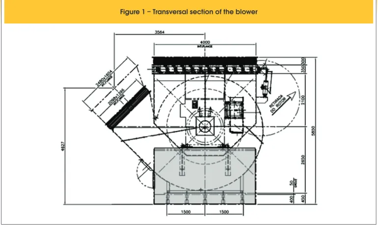
3.1 Characteristics of the equipment – Gas blower
The geometric dimensions of the equipment are shown in trans-versal and longitudinal sections in Figures 1 and 2, respectively.
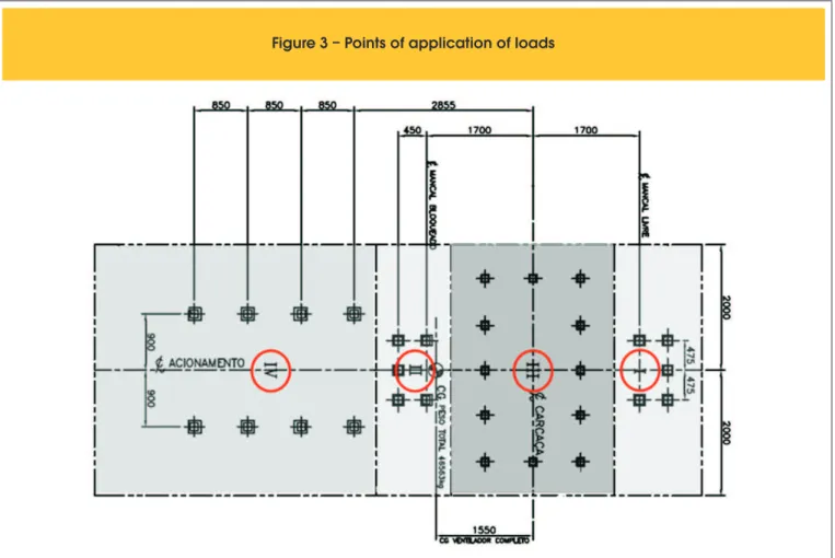
The loads and their respective application points are deined by
the equipment supplier. In Table 1 the static loads applied in
equip-ment areas I, II, III e IV and dynamic loads applied in areas I e II
are deined in Table 2, and shown in Figure 3.
The analyses were done for two different values of frequencies: in the blower frequency (19.75 Hz) and in the motor frequency (60 Hz). The results corresponding to these two frequencies were further
combined following the criteria deined by ISO 2372 [12], applying
the square root of the sum of the squares of the effective velocities obtained in the two frequencies.
3.2 Characteristics of the concrete block
The concrete block was designed following the recommendations of PETROBRAS document N-1848 [8]. The block centroid and the gravity center of the assemblage machine-block shall be in the same vertical line, being allowed a maximum eccentricity of 5% with relation to the corresponding dimension, according to these recommendations.
The block height was determined in order to be at least 1/5 of the
Figure 4 – Sketch of dimensions of the concrete block
Table 3 – Dimension of the blocks
Dimension of the blocks (m)
Shallow foundation
Pile foundation
A = 3.70
B = 1.70
C = 2.60
D = 1.20
A = 3.70
B = 2.70
C = 2.60
D = 1.20
E = 4.50
F = 3.35
G = 4.00
E = 5.50
F = 3.35
G = 4.00
Table 4 – Variation of G – shallow foundation
Soil shear modulus (kPa)
Shallow foundation
NSPT = 10
Model 1
Model 2
Model 3
~50% G
100% G
~150% G
smaller block dimension in plan, nor smaller than 1/10 of the block big-ger plan dimension. The block is in reinforced concrete, with fck = 30 MPa. The block dimensions were determined in order to be adequate to the equipment geometry, and are shown in Figure 4 and Table 3. Adopting for the pile foundation the same block dimensions consid-ered for the shallow foundation, obtained displacement amplitudes became inadmissible. It was necessary to increase the dimensions of this pile foundation, in order to have more mass, reducing in this way the displacements to admissible values.
3.3 Characteristics of the soil
The soil, under the action of the forces produced by the operation of the equipment, presents a very small level of deformations, in the order of some micra (µm). This corresponds to a very small level of strains, allowing to the consideration of the soil behavior as linear and elastic. The several regions of the soil were considered as homogeneous.
The several considered soil parameters are deined as follows.
3.3.1 Shear modulus (G), Poisson coeficient (ν) e speciic mass (ρ)
The soil shear modulus was empirically deined, due to the lack of speciic tests for its determination. This parameter was evaluated
as a function of the number of blows in the Standard Penetration
Test (SPT), according to OHSAKI and IWASAKI [15]:
(5)
8 , 0 spt
)
N
(
5
,
11
G
=
´
The number of blows in the SPT varies with the soil depth. These values were defined from the test report more repre-sentative for the analyzed foundation. Due to the imprecision of the adopted empirical formula and also due to the process of uniformization of the soil properties, a parametric variation of 50% of increase/decrease in the value of G was considered. The G values used in the three soil conditions are presented in Tables 4 and 5.
The value of n = 0.35 was adopted for the Poisson coeficient. The
eventual variation in the numerical value of this parameter has an
inluence in the results much smaller than the variation in the values of G. For the speciic mass the value of ρ = 1.8 t/m³ is considered.
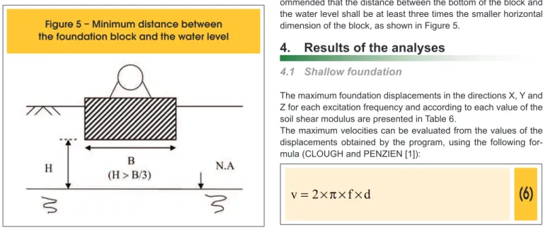
3.3.2 Consideration on the phreatic water level
The presence of high phreatic water lever leads to an ampliication
on the vibrations, propagating them to long distances, and also can lead to the compactation in saturated sand layers. In this way, in order to make possible a solution in shallow foundation, it is rec-ommended that the distance between the bottom of the block and the water level shall be at least three times the smaller horizontal dimension of the block, as shown in Figure 5.
4. Results of the analyses
4.1 Shallow foundation
The maximum foundation displacements in the directions X, Y and Z for each excitation frequency and according to each value of the soil shear modulus are presented in Table 6.
The maximum velocities can be evaluated from the values of the displacements obtained by the program, using the following for-mula (CLOUGH and PENZIEN [1]):
(6)
d
f
2
v
=
´
p
´
´
Table 5 – Variation of G – pile foundation
Soil shear modulus (kPa)
Model 1
Model 2
Model 3
~50% G
100% G
~150% G
pile foundation
st
1 layer - NSPT = 10
2 layer - NSPT = 26
nd3 layer - NSPT = 53
rd30000
72500
108000
80000
160000
240000
135000
270000
405000
where:
v = velocity (mm/s)
f = frequency of operation (Hz) d = displacement (mm)
As there are two different frequencies of operation, the effective
velocities are deined as a function of the above determined veloci -ties, with the following equation:
(7)
(
v
v
)
/
2
v
22 2 1
rms
=
+
In this way, the effective velocity is obtained by the combination of the velocities for the frequencies of 19.75 Hz e 60 Hz, as presented in Table 7.
According to ISO 2372 [12], the analyzed equipment can be
classi-ied as a Heavy Machine (Class III). Velocities up to 1.8 mm/s are classiied in the optimal range, between 1.8 and 4.5 mm/s are in
the acceptable range, between 4.5 a 11.2 mm/s in are the tolerable range and the velocities superior to 11,2 mm/s are non-tolerable. The maximum obtained velocity was 2.91 mm/s, occurring in the
Table 6 – Maximum displacements in directions X, Y and Z for each G value
f (Hz)
(kN/m )
G
2Translation X
(10 mm)
-3Translation Y
(10 mm)
-3Translation Z
(10 mm)
-319,75
60,0
30000
72500
108000
30000
72500
108000
5.2
5.1
5.1
0.2
0.3
0.4
19.8
28.2
32.6
1.9
1.9
2.0
18.8
20.1
20.6
1.9
1.9
2.0
Table 7 – Effective velocities in directions
X, Y and Z for each G value
Effective velocities
2
G (kN/m )
Velocity X
(mm/s)
Velocity Y
(mm/s)
Velocity Z
(mm/s)
30000
72500
108000
0.46
0.46
0.46
1.81
2.53
2.91
1.73
1.84
1.88
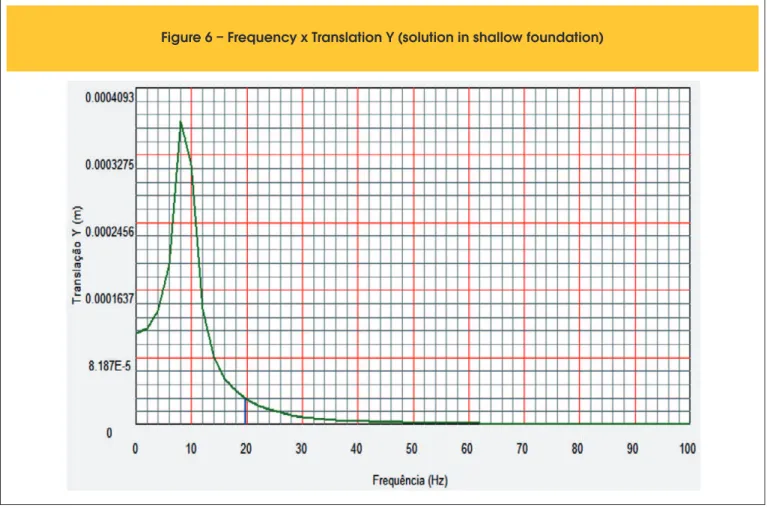
horizontal direction (Y), for the bigger value of shear modulus (G). This velocity is then in the acceptable range. Therefore, according to the criteria established in ISO 2372 [12], and also consider-ing that the eigenfrequency of the foundation is far from the excit-ing frequency, as shown in Figure 6 (obtained with the program BLOCKSOLVER), the proposed solution is acceptable.
In the other hand, considering the most representative SPT report, it can be seen that the water lever is in a distance closer than three times the smaller dimension of the block, it can be concluded that a solution in piles shall be also analyzed.
4.2 Pile foundation
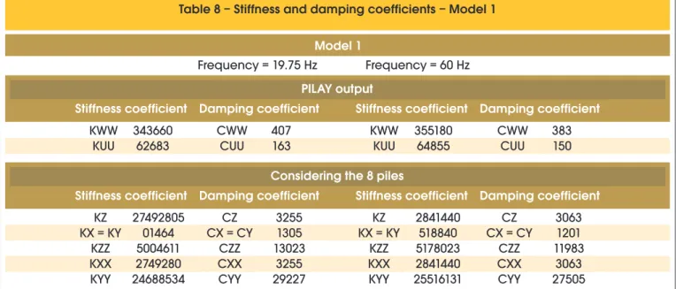
For the three considered conditions of soil stiffness (Models 1, 2
and 3) the values of the stiffness and damping coeficients ob
-tained by the program PILAY, as well as condensed coeficients in
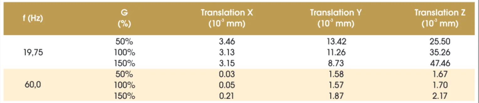
the center of the block, are presented in Tables 8, 9 and 10 for each one of the frequencies of operation. In this evaluation, considering the distance between piles, the group effect was disregarded. The displacements of the foundation in directions X, Y and Z for
each frequency of excitation and according to each value of soil shear modulus are presented in Table 11. The effective velocities, resulting from the combination of the velocities for the different fre-quencies, are presented in Table 12. The maximum found effective velocity was 4.20 mm/s, occurring in the vertical direction (Z) for the bigger value of the shear modulus (G), and is in the acceptable
classiication range. In this case, the eigenfrequency is still far from
the frequency of excitation, as shown in Figure 7.
As for the pile foundation there are not restrictions regarding the water level, this solution becomes more adequate relatively to the shallow foundation.
5. Conclusions
In this paper, the procedure followed for making possible the foundation for a typical equipment with dynamic loads in an in-dustrial plant is presented. For this, a comparative analysis was done between solutions in shallow and pile foundations. Through the use of the programs PILAY and BLOCKSOLVER it was pos-sible to evaluate the foundation displacements caused by the
dy-Table 8 – Stiffness and damping coefficients – Model 1
Model 1
PILAY output
Considering the 8 piles
Frequency = 19.75 Hz
Stiffness coefficient
Stiffness coefficient
Stiffness coefficient
Stiffness coefficient
Damping coefficient
Damping coefficient
Damping coefficient
Damping coefficient
KWW
KUU
343660
62683
KZ
KX = KY
KZZ
KXX
KYY
KZ
KX = KY
KZZ
KXX
KYY
27492805
01464
5004611
2749280
24688534
2841440
518840
5178023
2841440
25516131
KWW
KUU
355180
64855
CWW
CUU
CZ
CX = CY
CZZ
CXX
CYY
CZ
CX = CY
CZZ
CXX
CYY
CWW
CUU
407
163
3255
1305
13023
3255
29227
3063
1201
11983
3063
27505
383
150
Frequency = 60 Hz
Table 9 – Stiffness and damping coefficients – Model 2
Model 2
PILAY output
Considering the 8 piles
Frequency = 19.75 Hz
Stiffness coefficient
Stiffness coefficient
Stiffness coefficient
Stiffness coefficient
Damping coefficient
Damping coefficient
Damping coefficient
Damping coefficient
KWW
KUU
472230
117830
KZ
KX = KY
KZZ
KXX
KYY
KZ
KX = KY
KZZ
KXX
KYY
3777840
942640
9407547
3777840
33925003
3849680
968240
9663035
3849680
34570126
KWW
KUU
121030
481210
CWW
CUU
CZ
CX = CY
CZZ
CXX
CYY
CZ
CX = CY
namic loads. In this way, the foundation displacements can be well controlled and limited.
From the obtained values of displacements, the corresponding ef-fective velocities were determined. Considering that the analyzed equipment presents two frequencies of excitation, the effective velocities were determined through the combination of results. In the analysis of the shallow foundation, the maximum obtained ve-locity was 2.91 mm/s, occurring in the horizontal direction (Y). In the analysis of the pile foundation, the maximum obtained velocity was 4.20 mm/s, occurring in the vertical direction (Z). Although the velocity in the pile foundation is 40% bigger than the one in the shallow foundation, both are in the acceptable range, according to the criteria established by ISO 2372 [12].
Analyzing the reports of the more representative SPT test, it can be observed that the water level is a distance closer than three times the smaller block dimension. Therefore, the pile foundation is considered as the best solution.
In order to obtain satisfactory results for the solution in piles, it was necessary to increase the foundation mass, increasing the horizon-tal block dimensions, in order to reduce displacements and separate
the eigenfrequencies from the frequency of operation. The dificulty
for this increase of the mass was the restriction imposed by the adja-cent foundations, in order to avoid interferences with them.
6. References
[01] CLOUGH, R.W.; PENZIEN, J. Dynamics of Structures, McGraw-Hill Book Co – Second Edition, Singapore, 1993.
[02] SOUZA LIMA, S.; SANTOS, S.H.C. Análise Dinâmica das
Estruturas, Editora Ciência Moderna, Rio de Janeiro, 2008.
[03] BRASIL, R.M.L.R.F; SILVA, M.A. Introdução à Dinâmica das
Estruturas, Editora Edgard Blücher, São Paulo, 2013. [04] ARYA, S.; O’NEILL M.; PINCUS, G. Design of Structures
and Foundations for Vibrating Machines, Gulf Publishing, Houston, 1979.
[05] BATHIA, K.G., Foundations for Industrial Machines, D-CAD Publishers, New Delhi, 2008.
[06] DEUTCHES INSTITÜT FOR NORMUNG. DIN 4024-1 – Machine Foundations; Flexible Structures that Support Machines with Rotating Elements. 1988.
Table 10 – Stiffness and damping coefficients – Model 3
Model 3
PILAY output
Considering the 8 piles
Frequency = 19.75 Hz
Stiffness coefficient
Stiffness coefficient
Stiffness coefficient
Stiffness coefficient
Damping coefficient
Damping coefficient
Damping coefficient
Damping coefficient
KWW
KUU
559250
156710
KZ
KX = KY
KZZ
KXX
KYY
KZ
KX = KY
KZZ
KXX
KYY
4474000
1253680
12511726
4474000
40176520
4535520
1280960
12783981
4535520
40728970
KWW
KUU
566940
160120
CWW
CUU
CZ
CX = CY
CZZ
CXX
CYY
CZ
CX = CY
CZZ
CXX
CYY
CWW
CUU
428
216
3421
1731
17273
3421
30722
3372
1705
17015
3372
30284
422
213
Frequency = 60 Hz
Table 11 – Displacements in directions X, Y and Z for each G value
f (Hz)
(%)
G
Translation X
(10 mm)
-3Translation Y
(10 mm)
-3Translation Z
(10 mm)
-319,75
60,0
50%
100%
150%
50%
100%
150%
3.46
3.13
3.15
0.03
0.05
0.21
13.42
11.26
8.73
1.58
1.57
1.87
25.50
35.26
47.46
1.67
1.70
2.17
Table 12 – Effective velocities in directions
X, Y and Z for each G value
Effective velocities
G (%)
Velocity X
(mm/s)
Velocity Y
(mm/s)
Velocity Z
(mm/s)
[07] DEUTCHES INSTITÜT FOR NORMUNG. DIN 4024-2 – Ma-chine Foundations; Rigid Foundations for MaMa-chinery with Periodic Excitation. 1991.
[08] PETROBRAS. N 1848 – Projeto de Fundações de Máqui-nas. 2008.
[09] AMERICAN CONCRETE INSTITUTE. ACI 351.3R-04 - Foundations for Dynamic Equipment, 2011.
[10] COUTINHO, D.S.A.; MENDES, C.H.F. Projecto Automatiza-do de Fundações de Máquinas. Projeto Final de Curso, Rio de Janeiro, DME/POLI/UFRJ, 2007.
[11] NOVAK, M.; ABOUL-ELLA, F. PILAY – A Computer Program for Calculation of Stiffness and Damping of Piles in Layered Media. Systems Analysis Control and Design Activity (SAC-DA), The University of Western Ontario, London, Canada, 1977.
[12] INTERNATIONAL ORGANIZATION FOR STANDARDIZA-TION. ISO 2372 – Mechanical Vibration of Machines with Operation Speeds from 10 to 200 rev/s, 1974.
[13] MACABÚ, L.P. Análise Comparativa de Soluções em Funda-ção Direta e Sobre Estacas para um Equipamento em uma Instalação Industrial. Projeto de Graduação, Departamento de Estruturas, Escola Politécnica da UFRJ, Setembro de 2011.
[14] WOLF, P.J. Foundation Vibration Analysis Using Simple Physical Models, Prentice Hall, 1994.
[15] OHSAKI, Y.; IWASAKI, R. On dynamic shear moduli and Pois-son’s ratio of soil deposits. Soil and Foundations, JSSMFE, v.14, nº4, p. 59-73, Dec. 1973.