This is an Open Access article distributed under the terms of the Creative Commons Attribution Non-Commercial License
theoretical attempts of definition and practical observations. This paper intends to contribute to a serious discussion of something trivial, indeed very well-known or used among welding experts, but actually yet hardly understood, at least as when it comes to closer examination
Key-words: Arc length; Controlled GMAW; Spray arc; Electrode tapering.
1. Introduction and Theoretical Approach
BS 499-1:2009 [1] describes ‘arc length’ as the “distance from the tip of the welding electrode to the adjacent surface of the weld pool”. An investigation [2] of high performance gas metal spray arcs aimed at the evaluation of differences generated by either the varying consumables or the power source type used and was also employing high-speed cinematography. One of the chosen details to determine: variation in arc length. Independently of equipment and consumables used, it was found difficult in general however, precisely to define the length of the welding arc. It often proved even impracticable to accurately determine the wire electrode tip and as such the gap between the tip and the weld pool, enveloped by the arc plasma. Aware of this, a research of the welding literature on arc length definition was conducted attempting to reveal deeper sense. Surprisingly very little information was found though on a technical term, extensively used in welding.
Instances were compiled providing different viewpoints on arc length issues to stimulate a more quantitative approach to the ‘arc length’. For example, Gülsöz [3] studied the melting behaviour of coated electrodes applying direct- (straight- and reverse polarity) as well as alternating current shielded metal arc welding (SMAW). Although explicitly using ‘arc length’ to describe his observations the author provides only a ‘theoretical’ definition, as in Figure 1, which schematically depicts the arc length representing the distance between anode and cathode. Greyscale high-speed cinematography, however, proves the difficulties in transferring theoretical models to real environment, as seen Figure 2. The arc, described as “climbing” along with the cathode spot in [3], varies considerably in its shape. Also, the actual weld pool surface remains undefinable. Arc voltage is explained to have considerable or proportional effect on arc length. Increasing voltage leads to arc extension and vice versa.
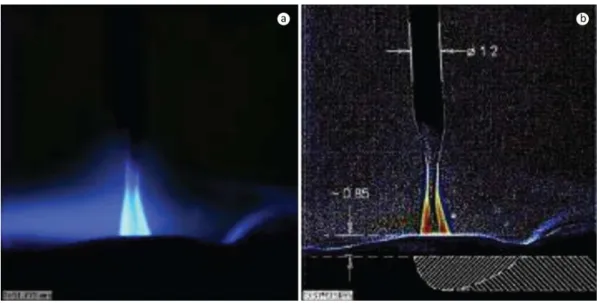
Similar to BS 499-1:2009, the ASM Metals Handbook [4] deals with arc length in shielded metal arc welding as “[...] the distance from the molten tip of the electrode core wire to the surface of the molten weld pool”. Droplet growth, depending on coating flux composition, short circuit frequency etc. are considered influencing the arc length. Bohlen [5] describes arc length based on a schematic representation of a gas tungsten arc, Figure 3. The arc is considered bridging the gap between anode (work piece) and cathode (tungsten electrode).
Real observations of gas tungsten arcs provide quite different arc shapes though and, in conjunction, arc lengths, Figure 4. According to Kou [7], who has conducted own, and reviewed research from other investigators (Friedman and Glickstein [6] and Key [8]), a This paper is based on IIW Document
No. XII-2013-11 which was subjected to
appropriate revision to achieve its inal
Figure 1. Schematic arc discharge representation (after [3]).
Figure 3. Schematic gas tungsten arc representation (after [5]).
Figure 4. (a) Influence of tungsten electrode vertex angle on arc shape (after [6]); (b) different power density in dependence on electrode included angle (after [7]).
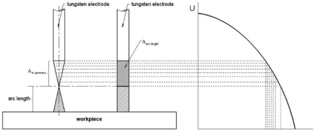
Figure 6 schematically represents the relationship between arc length and electrode geometry. Assuming the tapered electrode (Figure 6 left) is reduced incrementally from the tip (horizontal dashed lines) towards reaching a vertex angle of finally 180° (marked by the continuous horizontal line), the geometry influence decreases. Keeping the welding torch distance constant while only varying the electrode tip geometry, leads to considerable different arc length (denoted by
∆
arc length_ ). Assuming now a changing electrode geometry, a welder would attempt to manually balance the arc length by adjusting the distance between electrode and work piece surface for maintaining the ‘arc length’ constant. Wear, e.g., occurring through welding is suggested reducing the electrode length, leading to increasing arc length and thus requiring the welder to correspondingly adjust the electrode tip to work distance (ETWD) and approaching the electrode tip towards the work piece.Figure 6. Schematic representation of arc length variation in dependence on electrode geometry at constant welding torch distance and drooping power supply characteristic.
Employing Gas Metal Arc Welding (GMAW), the dynamic arc behaviour drastically changes due to the continuously fed and melting wire electrode. Literature reveals only little information on an actual ‘arc length’ definition Figure 7, taken from [5] e.g. represents a typical characteristic for a larger diameter mild steel wire electrode used for pure carbon dioxide GMAW. Even though qualitative designations such as ‘long’ and ‘short’ are used to determine specific arc length regions, no substantial or quantitative information is provided in regards to how arc length is measured through welding. Scotti [10], recognising the contradictions as when ‘arc length’ is involved for quantitatively describing welding arc phenomena, has extensively considered arc length in GMAW. Mapping droplet transfer modes in stainless steel GMAW, arc length is assessed the “more independent variable” vs. arc voltage and played an essential part in the studies conducted. Even though basically using a similar approach as [1], the author explicitly underlines the importance of process variables influencing arc length; e.g. depth of penetration, producing a cavity rather unpredictable and below the work piece surface, and as such, a substantial factor in changing the actual length of the arc, see Figure 8.
Figure 7. Arc characteristics for ø 1.6 mm GMAW mild steel electrode under pure CO
“Arc behaviour during welding” was investigated by Yudodibroto [11]. Amongst others, the author dealt with the definition of arc length in pulsed gas metal arc welding. As such, arc length was represented as specified in [1] but also defined by different regions of brightness, derived through an arbitrary greyscale image obtainable from using special software, see Figure 9. More recently Huismann [12] was suggesting an approach to determine arc length as a function of voltage measured within the weld circuit, incorporating and compensating, however, the influences capable of affecting measured output. Employing both a special weld power source and additional software, the author claims the derivation of a signal, showing “better correlation to the arc length than the normally used mean voltage”.
Figure 8. Schematic representation of the arc geometry: ‘Sout’ denotes electrode extension; ‘CTWD’ is contact tube to work distance; ‘PH’ is for pool height and ‘P’ is depth of penetration (after [10]).
Focusing on pulsed gas metal arc welding (GMAW-P), the term ‘arc length’ is suggested becoming more meaningful, since often related to features provided by electronically controlled power sources, e.g. ‘arc length control’. It appears obvious hence, that controlled gas metal arc welding processes, produced by advanced welding equipment, in general may enable a more precise definition of a secondary stage parameter, referred to as arc length; thereby achieving a more predictive or quantitatively more reasonable character. Figure 10 highly resolved depicts a GMAW-P droplet detachment sequence applying ø 1.2 mm AA 4043 filler wire and argon shielding gas. Beginning upper left through lower right it reveals a view on both background- and pulsed current phase and reflects defined wire tip melting before the produced droplet is detached.
Figure 10. GMAW-P droplet detachment sequence.
Simplifying these conditions, the average arc length may be expressed by Equation 1:
_ 1 _ 2 _
arc av arc max arc min
l
= ⋅
c L
+ ⋅
c L
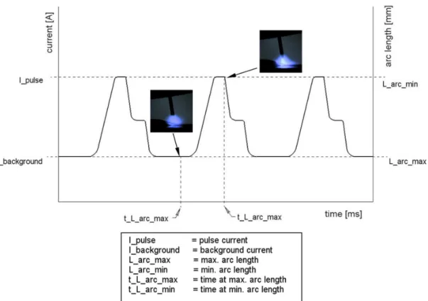
(1)where larc_av stands for average arc length, larc_max for maximum arc length, larc_min for minimum arc length and c1 and c2 are constants, expressing the correspondence of background current- and pulsed current ime. Based on the schemaic representaion of a pulsed arc cycle, see Figure 12, the expression implies an actual suiciency by obtaining the total average arc length by forming the arithmeical average of the maximal and minimal arc length. This paricular average length, represening an average arc performance, may be esimated of leading to an average fusion behaviour or -proile, respecively.
Figure 11. GMAW-P arc background- and pulsed current sequence.
It is understood from the literature that different approaches are applied when arc length is concerned. Non-consumable electrode welding processes, such as gas tungsten arc- or plasma welding may be considered “suitable” to evaluate this parameter. Controlled GMAW processes, e.g. pulsed gas metal arc welding, appear discussable for arc length detection, due to providing sufficiently predictable data in terms of droplet growth and droplet detachment.
2. “Conventional” Gas Metal Arc Welding
“Conventional” gas metal arc welding, using the regular short circuit-, globular- and spray arc mode, is broadly employed despite the advances in welding power source manufacturing. Especially the gas metal spray arc seems to undergo an ‘artificial’ renaissance since proving suitable for high performance weld applications. In this conjunction it appears reasonable to ask in how far the arc length term can be considered useful; or, in how far the aforementioned definitions are maybe transferable to spray arc conditions. The spray arc is broadly agreed arising as a natural physical phenomenon, influenced in particular by the weld current applied to the wire electrode. Spray arc conditions can be obtained exceeding a so-called ‘transition current’, whose height depends amongst others on the consumables used as well as on electrode diameter and extension [10,13]. Figure 13 indicates the difficult precise arc length detection in observing a spray arc through a tinted glass; i.e. from a welder’s perspective and using ø 1.2 mm G3 Si1 (EN 440) wire electrode and 82 Ar / 18 CO2 shielding gas.
Figure 13. Different external views upon gas metal spray arc: (a) Normal view; and (b) greyscale image captured through tinted glass.
A human welder, even if well trained, can hardly assess ‘arc length’ due to limited physiological capabilities. Hence, accurately validating the exact arc to wire electrode attachment position in turn leads to only relative arc length assessment.
3. Suggestion for a Distinct Aapproach in Arc Length
However, virtually expanding the “welder’s view”, Figure 15 represents a high-speed cinematography sequence conducted in connection to [2]. The ø 1.2 mm wire electrode was G3 Si1 (EN 440), shielding gas was 82 Ar/18 CO
2 and
wire feed rate was adjusted for correspondingly achieving ‘streaming’ transfer. Figure 15a shows the regular high resolution arc image; Figure 15b, c whereas exhibit the same exposure using however a special high speed camera filter technique (Edge Laplacian 5×5). Four different arc lengths, suggested correlating to different temperature distributions, could be detected actually from the filtered section. I.e. basically the ‘arc length’ complying with the definition in BS 499-1:2009 [1], as also three further length regions, denoted ‘L_1; L_2 and L_3 were found attached to the wire tip. Additionally the coincidental behaviour of droplet generation, droplet growth and droplet detachment, suggests the complexity of ‘correct’; i.e. quantitative arc length evaluation.
Figure 14. High speed image sequences of different droplet transfer modes (after [13]).
Increasing the shielding gas carbon dioxide content shifts the transition current to higher values. The droplet volume increases, frequently joined by repelling action. Shielding gas composition is supposed hence to significantly affect average arc length prediction. Maintaining specific peripheral parameters (power source type, filler wire, wire feed speed, etc.) constant, degrading conditions can be found by employing shielding gases either producing chemical reactions (e.g. Ar/O2 mixtures), see Figure 14d, or heavily influencing droplet generation and -detachment by their inert chemical character (e.g. argon).
Figure 16a through d represents such an explosive droplet reaction using ø 1.2 mm G3 Si1 wire electrode and Ar + 4 O
2 shielding gas. Although an arc plasma is bridging the gap between wire electrode and work piece, it
becomes impracticable in such cases to quantify its ‘length’, or even to estimate an average arc length. Both due to the entirely accidentally affected droplet shape and position. Figure 17 finally represents a further example, using pure argon and a similar wire electrode as aforementioned while adjusting 13.0 mm contact tip to work piece distance (CTWD). The Figure 17 is supposed capable of revealing the obvious inadequacy of any ‘theoretical’ arc length definition. Although a stable arc is maintained neither the “tip of the welding electrode” nor the “adjacent weld pool surface” [1] are possible to exactly being determined.
Highly dynamic weld pool motion as also a permanently coincidentally affected droplet behaviour are preventing from arc length derivation. Figure 18a-d indicates weld pool height variation employing a streaming spray arc with constant CTWD. The missing, but needed, dependence between wire tip (invisible in this case) and weld pool surface leads to a remarkable restriction applying the known ‘arc length’ definition. On the contrary,
Figure 17. Streaming spray arc at 13.0 mm CTWD and pure argon as the shielding gas.
this instance practically achieved, also underlines the theoretical considerations of Scotti on the importance of “pool height” and “penetration” massively affecting arc length quantification [10].
4. Discussion
The question remains: “How to “correctly” determine arc length?” Theoretical means, as provided by the standards [1,4], are shown hardly holding at closer investigation, but scientific research [10-12] nonetheless suggested that arc length, as a quantitative factor, may valuably contribute in describing welding phenomena. That is. Arc length can be meaningful employing welding processes and/or the welding conditions allowing for high level of prediction, e.g. with gas tungsten arc welding. Also, controlled or advanced consumable electrode arc welding processes, such as pulsed gas metal arc welding, may be stated; given, however, that specific and constant peripheral conditions apply. On the other hand it could be shown, that ‘arc length’ can become rather meaningless when employing welding processes or conditions subject to stochastic behaviour; e.g. streaming spray arc with high and varying depth of penetration.
It is thus suggested basically to attempt a separation. An example, already used before, shall be described hereafter to clarify this approach. Figure 19a, b shows two parts of Figure 11, and the same but graphically modified images are depicted in Figure 19c, d. Noticeably, Figure 19a, c represent a condition fairly similar to stationary gas tungsten arc welding. That is, precise droplet growth and wire feed rate control allow for arc length determination related to time. Figure 19c however, represents both a condition as known from controlled gas metal arc welding (approx. 2.0 mm arc length), but also a condition known from highly dynamic gas metal spray arc welding (approx. 4.0 mm arc length), see Figure 15c. Both regions attached at the wire electrode are suggested representing a specific amount of energy to the filler and parent material, hence contributing to droplet growth and fusion profile.
Figure 20. Suggested approach to arc length definition.
Figure 21. Streaming GMAW spray arc and position of beginning tapering [2].
5. Conclusions
From these considerations the following conclusions are achieved.
• The arc length evaluation approach as dealt with in current welding standards is believed insufficient for precise quantification.
• Non-consumable electrode welding processes, e.g. GTAW, or consumable electrode welding processes, such as GMAW-P (providing almost constant and repetitive process conditions over time) are suggested similarly treatable for arc length evaluation.
• Highly dynamic affected, or “natural” welding processes, such as streaming spray arc gas metal arc welding, are subjected to stochastic conditions and, in accordance to broadly applied welding standards, are suggested preventing from precise arc length evaluation.
• High speed cinematography could reveal the “visual” arc length as too vague to be clearly quantified. However, a relatively clear and consistently detectable position at the wire electrode was found, suggested therefore proving a suitable means to reasonably define arc length. This position is connected to where the wire electrode begins to change its original solid shape and becomes tapered.
• Because of the lack of general understanding yet noticeable when using this term in a scientific sense and as a general conclusion from our own observations it is also suggested that a fundamental clarification on arc length definition appears still required.
Acknowledgements
The author wishes to express his sincere gratitude to Prof. Dr. Américo Scotti for stimulating discussions on this research topic.
References
[1] British Standards Institution – BSI. British standard BS 499-1:2009: welding terms and symbols part 1: glossary for welding, brazing and thermal cutting. London: BSI; 2009.
[2] Egerland S. The gas metal spray arc - an investigation on streaming transfer [MSc-thesis]. Bedford: Cranfield University; 2010. [3] Gülsöz A. Beitrag zum Abschmelzverhalten von dickumhüllten
Stabelektroden beim Gleich- und Wechselstromschweißen [PhD-thesis]. Düsseldorf: Leibnitz University Hannover; 1988. In German.
[4] American Society for Metals – ASM. ASM metals handbook: welding, brazing and soldering. Ohio: ASM; 1993. v. 6.
[5] Bohlen C. Lehrbuch des Schutzgasschweißens. 2nd ed. Essen: Girardet Verlag; 1982. In German.
[6] Friedman E, Glickstein S. An investigation of the thermal response of stationary gas tungsten arc welds. Welding Journal. 1976;55(12):408s-420s.
[7] Kou S. Welding Metallurgy. 2nd ed. Hoboken: John Wiley & Sons; 2003.
[8] Key BYJF. Anode - cathode geometry and shielding gas interrelationships in GTAW. Welding Journal. 1980;59(12):364s-370s.
[9] Munske H, Becken O. Handbuch des Schutzgasschweißens: Elektrotechnische Grundlagen, Schweissanlagen und Einstellpraxis. Düsseldorf: Deutscher Verlag für Schweißtechnik; 1970. In German.
[10] Scotti A. Mapping transfer modes for stainless steel gas metal arc welding. Science and Technology of Welding and Joining. 2000;5(4):227-234. http://dx.doi.org/10.1179/136217100101538254. [11] Yudodibroto B. Liquid metal oscillation and arc behaviour during
welding. Delft: Delft University of Technology; 2010.
[12] Huismann G. Determination of the arc length by measuring the arc voltage on a GMAW process. In Proceedings of the 17th International Conference on Joining Materials (JOM-17); 2013 May 5-8; Helsingør, Denmark. Helsingør: Institute for the Joining of Materials; 2013.
![Figure 1. Schematic arc discharge representation (after [3] ).](https://thumb-eu.123doks.com/thumbv2/123dok_br/18858736.417539/2.892.134.457.95.516/figure-schematic-arc-discharge-representation.webp)
![Figure 3. Schematic gas tungsten arc representation (after [5] ).](https://thumb-eu.123doks.com/thumbv2/123dok_br/18858736.417539/3.892.226.664.124.544/figure-schematic-gas-tungsten-arc-representation-after.webp)
![Figure 9. Pulsed arc length definition (after [11] ): (a) original high speed image section; (b) greyscale edited image;](https://thumb-eu.123doks.com/thumbv2/123dok_br/18858736.417539/5.892.215.682.568.1037/figure-pulsed-length-definition-original-section-greyscale-edited.webp)


![Figure 14. High speed image sequences of different droplet transfer modes (after [13] ).](https://thumb-eu.123doks.com/thumbv2/123dok_br/18858736.417539/9.892.242.646.97.560/figure-high-speed-image-sequences-different-droplet-transfer.webp)