Stress analysis on the free-end distal
extension of an implant-supported
mandibular complete denture
Abstract: A comparative and qualitative analysis of the tensions gener-ated in the cantilever region of an implant-supported mandibular com-plete denture was conducted using the three-dimensional inite element method. The mechanical properties of the components were input in the model and a load of 15 N was applied in pre-determined points. In the irst simulation, the load was applied on the occlusal surface of the irst premolar. In the second simulation, it was applied on the irst and sec-ond premolars. In the third simulation, it was applied on the irst and second premolars and on the irst molar. The different occlusion patterns produced similar tension distributions in the cantilever region, which fol-lowed a similar pattern in the three simulations. In all of the cases, the highest levels of tension were located in the region of the irst implant. However, as the loads were dislocated distally, the tensions increased considerably. The more extensive the cantilever, the more compromised will be the infrastructure, the prosthetic components and the implants. Regardless of the length of the cantilever, the highest tensions will al-ways be located in the region of the implant next to the load application point.
Descriptors: Dental occlusion; Dental implantation; Biomechanics. Gustavo Diniz Greco(a)
Wellington Corrêa Jansen(b)
Janis Landre Junior(c)
Paulo Isaías Seraidarian(d)
(a) PhD student in Restorative Dentistry,
Dental Clinic, School of Dentistry, Federal University of Minas Gerais (UFMG), Belo Horizonte, MG, Brazil.
(b) PhD in Engineering, Assistant Professor,
School of Engineering, Pontifical Catholic University of Minas Gerais (PUC-Minas), Belo Horizonte, MG, Brazil.
(c) PhD in Dental Materials, Assistant Professor; (d)PhD in Prosthodontics, Assistant Professor
– School of Dentistry, Pontifical Catholic University of Minas Gerais (PUC-Minas), Belo Horizonte, MG, Brazil.
Corresponding author:
Gustavo Diniz Greco
Rua Pedra Bonita, 924, Barroca Belo Horizonte - MG - Brazil CEP: 30430-390
E-mail: [email protected]
Introduction
There is a great controversy in the related liter-ature about which occlusion pattern should be es-tablished in dental rehabilitations using cantilever implant-supported prostheses.1-3 Since the beginning
of osseointegration, when the Brånemark protocol composed of a ixed prosthesis with ive or six im-plantations as pillars in the mental region and bi-lateral cantilevers was proposed, there has been an interest not only in determining the most suitable occlusal coniguration, providing a harmonious and effective disclusion, but also in understanding the relationships of this coniguration with the stomato-gnathic system.4 Thus, the relationship between the
involved occlusal factors and chewing muscles, mas-ticatory eficiency, bruxism, temporomandibular articulation, adjacent tissues, etc. has been investi-gated. Few consistent and scientiically sound con-clusions, however, have been reached. In the natu-ral dentition, the canine guide is the most frequent disclusion pattern during contacting border move-ments.5 The occlusion pattern may be considered a
critical factor for the longevity of osseointegrated implants. In the natural dentition, the presence of periodontal ligament leads the teeth to behave very differently from how osseointegrated implants do. The tensions transmitted to the components of the implants and to the bone/implant interface are thus totally different from those observed in the natural dentition. If the occlusal forces exceed the absorp-tion ability of the system, the implant will fail due to the overloads and to the poor distribution of the masticatory forces, amongst other factors.3,6 The
literature pertinent to this subject is still scarce in qualitative and quantitative evaluations of the ef-fects of the tensions generated on the prosthesis, prosthetic components, implants and supporting bone structure. The modeling of these tensions with computer graphics programs and the biomechanical analysis rendered by the three-dimensional inite ele-ment method (3D-FEM) are promissing alternatives for addressing the subject. In addition, they have the advantage of not being invasive and of allowing the study of regions that would otherwise be very difi-cult to gain access to. That is the case, for example, of the studies aimed at measuring the tensions,
com-pressions and displacements related to implants and respective supporting structures.
Thus, taking advantage of the availability of these technologies, the present study analyzed the biomechanical behavior of the implants and pros-thetic components supporting an implant-supported mandibular complete denture using the three-di-mensional inite element method (3D-FEM). The study’s purpose was to contribute to the understand-ing of the consequences of the tensions generated to the implants and supporting structures simulating the physiological occlusal conditions observed in the free-end distal extension of this kind of prosthesis.
Material and Methods
Using the program SolidWorks Ofice Premium
2006 (SolidWorks Corporation, Concord, MA, USA), three-dimensional models were drawn simu-lating an implant-supported mandibular complete denture with the features of a prosthesis produced following the Brånemark protocol. Hence, ive im-plants (Titamax II, Neodent, Curitiba, PR, Brazil)
were simulated as pillars, located in the inter-fora-men region of the inter-fora-mentum, upon which a complete denture was simulated with a metallic infrastructure in nickel-chromium (Wironia BEGO,
Bremer/Ger-many), with twelve artiicial teeth (Ivoclar Vivadent Ltda., São Paulo, SP, Brazil), i.e., from mandibu-lar left irst momandibu-lar to mandibumandibu-lar right irst momandibu-lar. A small gingival band in heat-cured acrylic resin (Classico/RMV, São Paulo, SP, Brazil) was simulat-ed, without contact with mucosal tissue, observing an area of 3 mm for hygienization.
The ive titanium implants were distributed ob-serving a distance of 4 mm between their platforms. All the implants were simulated as being cylindri-cal, with 13 mm in height and 3.75 mm in diameter, with external hexagon and a platform of 4.1 mm.
The prosthetic components, also made of titanium (Mini Pilar Cônico, Neodent, Curitiba, PR, Brazil),
were simulated with 3 mm in height and platform of 4.1 mm, and they were installed with a torque of 20 N to guarantee an accurate it (Figure 1).
mea-surements provided a distal extension of 12 mm on each one of the prosthesis extremities.
A gingival portion in heat-cured acrylic resin and 12 artiicial teeth were simulated over this infra-structure.
The coeficient of Poisson (E) and the Modulus of elasticity (v) of each one of the elements compos-ing the models were simulated followcompos-ing the values established in the pertinent literature. Hence, the following parameters were deined:
Spongy alveolar bone - 1,370 MPa (E) and 0.30 (v);
cortical alveolar bone - 13,700 MPa (E) and 0.30 (v);
nickel-chromium alloy - 188,000 MPa (E) and 0.28 (v);
titanium - 110,000 MPa (E) and 0.35 (v); acrylic resin - 2,700 MPa (E) and 0.35 (v). A load of 15 N was applied, distributed on the oclusal surface of different teeth according to three simulations:
In the irst simulation, the load was applied on the irst premolar;
in the second simulation, the load was distrib-uted on irst and second premolars;
•
•
•
• •
•
•
in the third simulation, the load was distributed on the irst and second premolars and on the irst molar.
The applied force was divided among the applica-tion points located right after the end of the metallic infrastructure, i.e., at a distance of 13 mm from the irst implant, as shown in Figure 2.
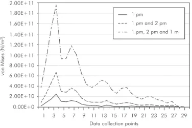
A total of thirty data collection points were uni-formly distributed extending over the nickel-chro-mium infrastructure, starting from the initial point of the cantilever on the working side (point 01) and extending to the end point of the cantilever on the balancing side (point 30).
For each of the simulations studied, the values obtained for the displacement magnitude (vectorial average of the displacements in the main axes x, y and z) were recorded in the form of graphs and com-pared.
Results
The results from the analysis of the distribution of the tensions on the nickel-chromium infrastruc-ture, on the prosthetic components and on the im-plants are presented in Figures 3 through 8.
The distribution of the occlusal loads in the three •
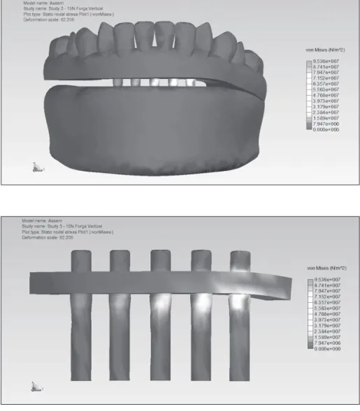
Figure 1 - Finite element model of an implant-supported mandibular complete denture.
Figure 3 - Occlusal load applied on the first premolar.
Figure 4 - Occlusal load applied on the first premolar. Anterior view and working side.
simulations generated stress information on the data collection points distributed over the extension of the metallic nickel-chromium infrastructure, as shown in Graph 1.
Analyzing the graph of the tensions generated on the metallic nickel-chromium infrastructure, on the prosthetic components and on the implants, it can be observed that the greatest tensions are located next
0.00E+0 5.00E+10 1.00E+11 1.50E+11 2.00E+11 2.50E+11
6.67E+10
1.95E+11
2.51E+10
vo
n
Mis
es
(N
/m
2)
1 pm
1 pm and 2 pm
1 pm, 2 pm and 1 m
Graph 2 - Maximum tension values in the three simulations of the study (pm: premolar; m: molar).
Graph 1 - Analysis of the tensions generated by the occlu-sion loads applied in the three simulations of the study (pm: premolar; m: molar).
0.00E+0 4.00E+10
2.00E+10 8.00E+10 1.20E+11
6.00E+10 1.00E+11 1.40E+11 1.60E+11 1.80E+11 2.00E+11
1 3 5 7 9 11 13 15 17 19 21 23 25 27 29
vo
n
Mis
es
(N
/m
2)
to the loading points, on the metallic infrastructure and around the irst implant. From the second im-plant on, towards the free-end of the balancing side, the tensions gradually decrease in all the three simu-lations.
It can also be observed that the proiles of the curves generated in the three simulations follow a same pattern, indicating that the load application on the cantilever generates tensions on the same points of the infrastructure, even while varying the posi-tion of these applicaposi-tions.
On the other hand, when the load is applied more distally (on the irst and second premolars in the second simulation; on the irst and second pre-molars and on the irst molar in the third simula-tion), even though the total load remains the same (15 N), the stress endured by the infrastructure is considerably bigger in the second and third simula-tions, as shown in Graph 2.
Discussion
Several renowned authors1,5,7-12 have stated that
to decrease the lever arm, the length of the cantile-ver in mandible should not exceed 20 mm. Others argue that the length of the cantilever should not ex-ceed two times the width of a premolar.13 Yet others
say that the length of the cantilever should not ex-ceed the anteroposterior length of the area where the implants are distributed, and that an implant distri-bution with an anteroposterior length greater than 11.1 mm will produce a cantilever length which is adequate to promote satisfactory biomechanics, in addition to producing a favorable esthetic and pho-netic result.14,15
The greater the length of the cantilever, the great-er will be the tensions gengreat-erated on the implants next to it. The load application (vertical, horizontal, or latero-horizontal) on the cantilever will produce a compression tension on the more distally positioned
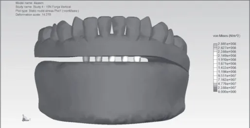
Figure 5 - Occlusal load applied on the first and secondpremolars.
implant, and a pull tension on more proximally po-sitioned implants.5,13-18
The tensions on the implants closer to the load application point are 1.75 to 3.5 times greater than those produced by application of a same load on a system without a cantilever.10 Based on these
re-ports, it is recommended that the arches of a free-end prosthesis be joined by a metallic infrastructure so that the implants on one side may help balance the tensions generated on the other.
In a study retrieved from the related literature, a prosthesis with two teeth in cantilever was evalu-ated, and the forces of closing and chewing were assessed. First, the irst tooth of the cantilever was placed in occlusion and the second tooth, in infra-occlusion; then, the opposite situation was created and analyzed. Based on the results of the study, the authors recommend that the second tooth should al-ways be placed in infra-occlusion.19
A judicious evaluation of the implant to be placed next to the cantilever should always be made before determining the length of the cantilever.16 If the
ter-minal implant does not have enough support and/or lacks proper size, the arm of the cantilever will have to be drastically reduced or its use should even be altogether avoided.
The distribution of the vertical and lateral loads applied to an implant-supported prosthesis depends on the number, arrangement and resistance of the implants used, as well as on the form and resistance of the prosthetic restoration itself. Prostheses with cantilevers have to endure an increased load on the implants next to their distal extensions.20 The
appli-cation of loads on the infrastructure of an implant-supported prosthesis produces a certain amount of deformation energy on the system. As a result, de-formation and delection of the infrastructure are to be expected. If a great amount of deformation en-Figure 8 - Occlusal load applied on the
first and second premolars and on the first molar. Anterior view and working side.
ergy is consumed close to the load application point (assuming that a high concentration of stress occurs around the closest implant), a great reduction in the energy transmitted to the remaining implants and low concentration of stress occurs on them.17
This stress distribution was observed in the pres-ent study during application of the occlusal loads in all the simulations.
Hence, the results of the present study were those expected, i.e., the greater the length of the cantilever, the greater will be the tensions endured by the infrastructure, and the distributions of these tensions are situated in the same regions, even if the
values of the tensions generated are much higher.
Conclusion
Based on the results of the present study, the fol-lowing conclusions were drawn:
The greater the extent of the cantilever, the more compromised will be the metallic infrastructure in nickel-chromium, the prosthetic components and the implants.
Regardless of the length of the cantilever, the greatest tensions will always be located on the region of the implant closest to the load applica-tion point.
•
•
References
1. Eskitascioglu G, Usumez A. The influence of occlusal loading location on stresses transferred to implant-supported prosthe-ses and supporting bone: a three-dimensional finite element study. J Prosthet Dent. 2004 Feb;91(2):144-50.
2. Guichet DL, Yoshinobu D, Caputo AA. Effect of splinting and interproximal contact tightness on load transfer by implant restoration. J Prosthet Dent. 2002 May;87(5):528-35. 3. Lin CL, Wang JC, Kuo YC. Numerical simulation on the
biomechanical interactions of tooth/implant-supported system under various occlusal forces with rigid/non-rigid connec-tions. J Biomech. 2006;39(3):453-63.
4. Krammer A, Weber H, Benzing U. Implant and prosthetic treatment of the edentulous maxilla using a bar-supported prosthesis. Int J Oral Maxillofac Implants. 1992 Sum;7(2):251-5.
5. Ogawa T, Ogimoto T, Koyano K. Validity of the examination method of occlusal contact pattern relating to mandibular position. J Dent. 2000 Jan;28(1):23-9.
6. Eckert SE, Laney WR. Patient Evaluation and Prosthodontic Treatment planning for Osseointegrated Implants. Dental Clin North Am. 1989;3(4):185-92.
7. Bidez MW, McLoughlin SW, Chen Y, English CE. Finite ele-ment analysis of four abutele-ment Hader bar designs. Implant Dent. 1993 Sum;2(3):171-8.
8. Bosse LP, Taylor TD. Problems Associated with Implant Re-habilitation of the Edentulous Maxilla. Dent Clin North Am. 1998;42(1):117-27.
9. Mc Cartney JW. Cantilever rests: an alternative to the unsup-ported distal cantilever of osseointegrated implant-supunsup-ported prostheses for the endentulous mandible. J Prosthet Dent. 1992;68(5):817-9.
10. Osier JF. Biomechanical local analysis of cantilevered implant systems. J Oral Implantol. 1991;17(1):40-7.
11. Shacketon JL, Carr L, Slabbert JC, Becker PJ. Survival of fixed implant-supported prostheses related to cantilever lengths. J Prosthet Dent. 1994 Jan;71(1):23-6.
12. Watson RM, Davis DM, Forman GH, Coward T. Consider-ations in design and fabrication of maxillary implant-support-ed protheses. Int J Prosthodont. 1991 May-Jun;4(3):232-9. 13. Pokorny GM, Solar P. Biomechanical of Endosseous Implant.
In: Watzek G. Endosseous implants: scientific and clinical aspects. Chicago: Quintessence; 1996.
14. Mc Alarney ME, Strauvopoulos D. Theoretical cantile-ver lengths versus clinical cases. J Prosthet Dent. 2000 Mar;83(3):332-43.
15. White SN, Caputo AA, Anderkvist T. Effect of cantilever length on stress transfer by implant-supported prostheses. J Prosthet Dent. 1994 May;71(5):493-9.
16. Assif D, Marshak B, Horowitz A. Analysis of load transfer and stress distribution by an implant-supported fixed partial denture. J Prosthet Dent. 1996 Mar;75(3):285-91.
17. Benzing UR, Gall H, Weber H. Biomechanical Aspects of two different Implant-Prosthetic concepts for Edentulous Maxil-lae. Int J Oral Maxillofac Implants. 1995 Mar-Apr;10(2):188-98.
18. Rangert B, Jemt T, Jörneus L. Forces and moments on Branemark implants. Int J Oral Maxillofac Implants. 1989 Fall;4(3):241-7.
19. Lundgren D, Falk H, Laurell L. The Influence of Number and Distribution of Occlusal Cantilever Contacts on Closing and Chewing Forces in Dentition with Implant-Supported Fixed Prostheses Occluding with Complete Dentures. Int J Oral Maxillofac Implants. 1989;4(4):277-83.