Comparative Evaluation of Tractor Trolley
Axle by Using Finite Element Analysis
Approach
Sanjay Aloni
PG(M.Tech CAD/CAM) Student of Department of Mechanical engineering, YCCE, Nagpur. [email protected]
Sandip Khedkar
Asst. Prof., Department of Mechanical engineering, YCCE, Nagpur [email protected]
Abstract :
Tractor trolley or trailers are very popular and cheaper mode of goods transport in rural as well as urban area. But these trailers are manufactured in small scale to moderate scale industry. Especially in the small- and middle-scale agricultural machinery industry, insufficient use of new technology and new design features can cause problems such as breakdowns and failures during field operations. In Present work finite element analysis approach is used to modify existing rear axle of tractor trolley. Fatigue failure of the rear axle finite element model was predicted after the dynamic load was imposed on it. For analysis, a 6.0 ton 2 wheeler tractor trolley i.e. semitrailer manufactured by Awachat Industries Ltd., Wardha is selected. The finite element analysis of existing rear axle of tractor trolley revealed the stresses distribution on rear axle. So, an effort is made to modify the design of existing rear axle along with change of material so that advantage of weight reduction along with safe stress can be obtained.
Keywords: Fatigue failure, finite element analysis, rear axle, ductile iron.
1. Introduction :
Farm tractor is an off road vehicle, used as a portable machine to do various useful works such as farming, haulage, heavy earthmoving & transportation. An off-road vehicle is considered to be any type of vehicle which is capable of driving on and off paved or gravel surface. Off road condition includes uneven agricultural field surfaces and bumpy village roads on which the tractor has to operate. These ground irregularities leads to unexpected loads coming on the tractor components [1].Tractor trolley or Trailers are widely used for transporting agriculture product, building construction material, industrial equipments & many other types of goods. Many varieties are available in trailer and use of particular trailer depends upon the application. The main requirements of trailer manufacturing are high performance with longer working life and robust construction. Tractor trolleys used for transportation are manufactured in small to moderate scale industries. Though tractor trolleys are manufactured of various capacities by various industries, there is a variation in manufacturing methods. The axle of a tractor trolley is one of the major and very important component and needs to be designed carefully, science this part also experiences the worst load condition such as static and dynamic loads due to irregularities of road, mostly during its travel on off road. Therefore it must be resistant to tolerate additional stress and loads.
drawbacks are that it does not allow each wheel to move independently in response to bumps, and the mass of the beam is part of the unsprung weight of the vehicle, which can further reduce ride quality.
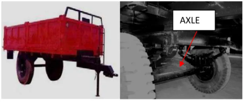
Fig. 1: Tractor Trolley Rear Axle Fitting
2. Investigation On Existing Rear Axle :
The tractor trolley axle under consideration is hot rolled square section of low carbon steel of cross section 75x75mm & length 1700mm, machined at both ends for fitment of hubs. The elemental analysis of materials is done on spectrometer and as per the component wt % found, steel belongs to SAE1020 standard of steel, as shown in Table 1, having typical microstructure as shown in fig 2 with around 25% of pearlite (black) & 75% of ferrite matrix (white).
Table 1: Chemical composition of the failedaxle shaft & SAE 1020 steel
Element Failed axle shaft SAE1020 steel
%C 0.207 0.17-0.23
%Si 0.187 0.15-0.35
%Mn 0.69 0.60-0.90
%S 0.015 0.05MAX
%P 0.029 0.04MAX
%Fe BALANCES BALANCES
Fig. 2: Typical microstructure of low carbon steel (SAE1020)
Visual examination of the failure axle shaft revealed that the fracture had been initiated close to the shaft, at the root from where the step turning starts for fitting of hub. This fracture location is to be expected because fatigue failures start at the most vulnerable point in a dynamically stressed area particularly where there is a stress raiser, as in our case sharp corners to facilitate proper sitting of bearing locking ring as shown in fig 3. The highest stress concentration and high residual stress would be anticipated to occur in this region. Typical macro-fracture appearance of the failed axle shaft is shown in fig 4.
End machining on axle for hub assembly
Fig. 3: Step turning at the end of shaft Fig. 4: Failure of the shaft at the root
The fracture surface of the failed axle shaft exhibits stress concentration regions as shown in fig4,where crack initiation starts (see mark A), progressive flat fatigue fracture regions (B), and the final fracture region produced by overload (C), as shown in fig 5.
Fig. 5: Fracture surface showing stress concentrated regions.
The fracture appeared to be typical of unidirectional bending fatigue under conditions of a low stress with a high stress concentration. From the above observations, it is clear that fatigue cracks have initiated at stress concentration points leading to fracturing of the axle shaft. When the local stress exceeds the material yield strength, it is possible to form a fatigue crack. Since the resistance of steel to fatigue initiation in proportional to its yield strength, the low properties of the steel in this case left it open to fatigue initiation [2][7]. The area of final fracture due to overload is large, approximately 40% of total area, indicating that the material is also not adequate for the applied stresses.
2.1 Building Finite Element Model Of Existing Rear Axle :
For the FE Analysis, it is necessary to create a solid model of axle and also to create a FE model. In the present work, static analysis has been carried out for the axle considering sudden load effects. As shown in figure 6 (i & ii), PRO-E is used for modeling the axle of tractor trailer. The model has a solid axle shaft of square cross sectional area of 75mmX75mm, machined at both ends with length 1700 mm. The model is discretized using hex dominant method for meshing with 22300 elements & 84759 nodes. This mesh method uses an unstructured meshing approach to generate a quad-dominant surface mesh and then fill it with a hex-dominant mesh. This approach generally gives nice hex elements on the boundary of a chunky part with a hybrid hex, prism, pyramid, tet-mesh used internally. Quick automatic hex or hex-dominant mesh can be generated, or a highly controlled hex meshes for optimal solution efficiency and accuracy.
Location of failure at the root
A
B
Fig. 6 (i): solid model of existing axle
Fig. 6 (ii): Hex meshed model of axle
2.2 Loads On Rear Axle Beam :
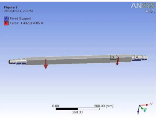
The total weight of fully loaded trailer including self weight of trolley is 7300 kg i.e. load capacity of 6000Kg & trolley weight of 1300Kg. This load is concentrated at two mounting points for leaf spring on the axle as shown in fig 7. Because of the vertical acceleration of lumped mass of the vehicle body due to the road surface roughness, maximum dynamic loading on each coil spring seat is estimated about twice as much as static loading [3][8][6] & load acting at each point is 7300x9.81x2/2=1.4323x105/2= 71615 N as shown in fig 6.The properties of Structural steel material of axle is shown in Table 2.
Fig7 : Loading of axle
Table 2 - SAE1020 steel constants.
Structural
Young's Modulus 2.05e+005 MPa
Poisson's Ratio 0.3
Density 7.87e-006 kg/mm³
2.3 Finite Element Analysis And Results :
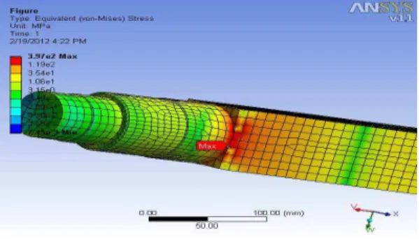
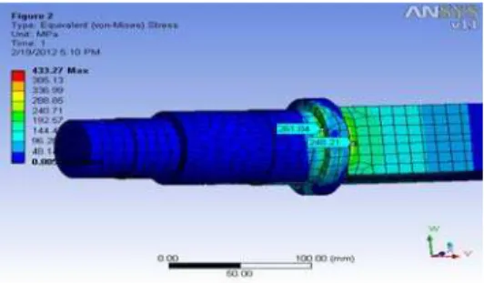
Figure 8 shows equivalent Von-Mises stress distribution provided from the FE analysis. Results show that there are tensile stress concentrated regions at transition area of axle hub mountings. Locations of the critical regions and the premature fatigue failure are the same as seen in Figure 3. The calculated Von- Mises stress is 397 MPa far above the material’s yielding stress. This means that axle not satisfies the safety conditions for maximum loading if it is exerted statically.
Fig. 8: Equivalent Von-Mises stress distribution on transition area
3. Modifications Suggested In Existing Axle:
From the investigation of material, manufacturing process & FE analysis it is seen that tensile stress concentrated regions are at transition area of axle hub mountings due to sharp corner at the start of step turning to facilitate proper fitting of bearing locking ring or spacer and this results into stress concentration area. Modification of existing axle is done aiming to avoid this stress concentration region which is possible if existing rear axle is manufactured with casting process and subsequently finished by machining operations at both ends for fitment of hub, as it is done in this work. The design flexibility offered by the casting process far exceeds that of any other process used for the production of engineering components. This flexibility enables the design engineer to match the design of the component to its function. Metal can be placed where it is required to optimize the load carrying capacity of the part, and can be removed from unstressed areas to reduce weight. Changes in cross-section can be streamlined to reduce stress concentrations. The result? Both initial and life-cycle costs are reduced through material and energy conservation and increased component performance. The main advantage with casting in present work is, bearing locking ring or spacer now becomes integrated part of as cast axle shaft which ultimately strengthened transition area.
3.1 Selection of Material:
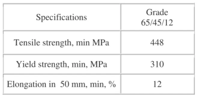
Ductile iron is competitive with steel in strength for a given level of ductility and 8-10% lower in specific gravity than wrought steel. (This is due to the presence of graphite in the cast iron matrix).Therefore, if the component stiffness is sufficient and a steel part can be replaced with an component of the exact same configuration, the part will weigh 8-10% less. To convert existing axle part into casting, suitable material which can compete with the properties of SAE1020 steel is chosen. ASTM A536-84(2004) 65-45-12(EN1536:1997,EN-GJS-450-12, BS2789:1985-450/12) Ductile iron was utilized for this process.The ASTM has five standards covering Ductile Iron castings. ASTM A536 is the most frequently used, covering the general engineering grades of Ductile Iron. This iron has approximately the same tensile and yield strengths as SAE 1020 steel in the as-rolled condition. The following specifications [4]as shown in table 3, conforms to ASTM A536 grade 65-45-12
Table3: ASTM A536 (65-45-12)Ductile Iron Castings tensile Requirements.
Specifications Grade
65/45/12
Tensile strength, min MPa 448
Yield strength, min, MPa 310
Elongation in 50 mm, min, % 12
3.2 Material Characteristics:
65-45-12 ductile iron contains nodular graphite (black) in a matrix of ferrite (white) with small amounts of pearlite(black). The ferritic structure gives excellent machinability with good surface finishes along with optimal impact strengths, fatigue properties. Ferritic/Pearlitic matrix obtained as cast. Having good machinability, excellent surface finish and very good strength. They present ultimate tensile strength and yield strength which is close to SAE 1020 steel grades. This grade is good for applications such as machine components that suffer impact and are crack-resistance. Table 4 showing the typical chemical composition of class 65-45-12 Ductile iron.
Table 4: Chemical composition of Ductile Iron of class 65-45-12
Element Percentage
C 3.3-4.0
Si 2.4-3.1
Mn 0.2-0.3
S 0.020 MAX
P 0.010 MAX
Mg 0.03-0.05
Magnesium is added to promote spheroidal graphite shape which is also called nodules of graphite as shown in fig 9of microstructure of this ductile iron.
Fig. 9: Microstructure of 65-45-12 ductile iron.
The nearly spherical shape of graphite removes the “crack” effect and, in fact, the graphite spheroids act as “crack arresters “as shown impressively in fig 10.
4. Building Finite Element Model Of Modified Rear Axle :
For the FE Analysis, it is necessary to create a solid model of axle casting & also to create a FE model. Solid modeling of axle casting with both ends machined is shown in fig11(i) where bearing locking ring or spacer is integrated part of as cast axle fig11(ii).
Fig.11 (i): solid model of modified axle
Fig11(ii): Transition area of modified axle
As done for the existing axle, static analysis has been carried out for the axle considering sudden load effects. As shown in figure 12, PRO-E is used for modeling the axle of tractor trailer. The model has a solid axle shaft of square cross sectional area of 67x67mm, machined at both ends with length 1700 mm. The model is discretized using hex dominant method for meshing with 17298 elements & 64118 nodes.
Fig. 12: Hex meshed model of modified axle
4.1 Finite Element Analysis And Results Of Modified Axle:
Considering similar load conditions for modified axle as that of existing axle as shown in fig13 the FE analysis is done. The properties of ductile iron of class 65-45-12 suggested for casting of axle is shown in table 5.
Fig13: Loading of existing axle
Table 5: Ductile Iron (65-45-12) constants.
Structural
Young's Modulus 1.69e+005 MPa
Poisson's Ratio 0.28
Density 7.2e-006 kg/mm³
Tensile Yield 310.00 MPa
Tensile Ultimate 448.00 MPa
Figure 14 shows equivalent Von-Mises stress distribution on modified axle provided from the FE analysis. Results show that there are tensile stress concentrated regions at transition area of axle hub mountings. Locations of the critical regions where existing axle fails due to premature fatigue crack, showing Von-Mises stresses maximum of which is 261.04 MPa far below the material’s yielding stress. This means that axle with suggested satisfies the safety conditions for maximum loading if it is exerted statically.
Fig. 14: Equivalent Von-Mises stress distribution on transition area of the axle
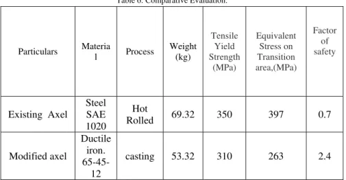
5. Comparative Evaluation :
Table 6: Comparative Evaluation.
Particulars Materia
l Process
Weight (kg) Tensile Yield Strength (MPa) Equivalent Stress on Transition area,(MPa) Factor of safety
Existing Axel
Steel SAE 1020
Hot
Rolled 69.32 350 397 0.7
Modified axel
Ductile iron. 65-45-12
casting 53.32 310 263 2.4
From table 3, it has been found that, maximum stress present in existing axle is 397 Mpa which is more than the tensile yield strength of material. Whereas maximum stress present in modified axle is 263 which is much less than the tensile yield strength of its material.We therefore conclude that the tractor trolley having modified axle will definatly work satisfactorily under this stress level without fatigue initiation .
It is also seen from the fig15 (i&ii), showing factor of safety in transition area of existing and modified axle respectively, factor of safety is increased in case of modified axle & weight is also reduced almost by 10%, i.e. from 69.326 to 53.328.
Fig. 15(i): FOS of modified axle
Fig. 15(ii): FOS of existing axle
6. Cost Reduction:
Conclusion :
This study was conducted on a existing rear axle shaft used in tractor trolley. Spectrum analysis revealed that the failed axle shaft material is SAE 1020 steel .Fractographic features indicated that fatigue was the main cause of failure of the axle shaft. It was observed that the fatigue cracks originated from transition areas due to sharp corners. Modified axle produced with casting process with the use of ductile iron (65-45-12 or 450-12) strengthened the transition area as bearing locking ring or spacer becomes the integrated part which is loose or assembled in case of existing axle. This ultimately solves the problem of initiation of fatigue cracks in this area. An application including both redesigning of the axle transition area and change of material i.e. suitable for casting of axle which may be a good alternative to enhance the fatigue life, while increasing weight to strength ratio and can satisfy minimum design criteria.
Acknowledgments:
The author would also like to thank Awachat Industries Ltd., Wardha & Jayaswal NECO Industries Ltd. Foundry, for their contributions to the data and case studies in this paper.
References:
[1] Non linear analysis of farm tractor front axle using ABAQUS CAE, Dr Sajan Pawar, Dr Prakash Kamath, Mr Rajesh Upadhyay. [2] Fatigue failure of a rear axle shaft of an automobile Osman Asi *
[3] Fatigue failure fault prediction of truck rear axle housing excited by random road roughness Meng Qinghua1*, Zheng Huifeng2 and Lv Fengjun3.
[4] Ductile Iron Data for Design Engineers, Ductile Iron Socity.
[5] Austempered Ductile Iron (ADI) - A Green Alternative for IndiaJohn R. Keough, PEng, FASM
[6] Assessment of Dynamic Load Equations Through Drive Wheel Slip Measurement,M. Naderi, R. Alimardani, R. Abbaszadeh and H. Ahmadi, American-Eurasian J. Agric. & Environ. Sci., 3 (5): 778-784, 2008ISSN 1818-6769© IDOSI Publications, 2008
[7] Fatigue and Fracture Toughness of Five Carbon or Low AlloyPublished by the Carbon and Low Alloy Steel. Technical Research Committee Steel Founders' Society of America DR. JOHN M. SVOBODATechnical and Research Director
OCTOBER, 1982