Najuka Hadkar Int. Journal of Engineering Research and Applications
www.ijera.com
ISSN : 2248-9622, Vol. 5, Issue 5, ( Part -4) May 2015, pp.11-14
www.ijera.com 11 | P a g e
Design of Square Shaped Miniaturized Split Ring Resonators
Najuka Hadkar, Santosh Jagtap
Vidyalankar Institute of Technology, Wadala, Mumbai Vidyalankar Institute of Technology, Wadala, Mumbai
ABSTRACT
Microwaves are constantly experiencing changes for many years. Microwave circuits use microstrip lines because it allows easy integration of active and passive surface mount components and it is less costly. In addition to a large number of benefits, microstrip lines have some disadvantages such as narrow-band loss, interference and low efficiency. To overcome the disadvantages, metamaterials are introduced. The proposed work shows various concentric U-shaped multi-split ring resonators(SRRs) metamaterial structures with & without broadside coupling. As compared to the conventional split ring resonators , broadside coupled resonators shows decrease in the LC resonance frequency and provide an electrically small and easy-to-fabricate alternative to the present multi-band metamaterial structures. The multi-band magnetic resonator topologies are simulated using CST Microwave Studio (MWS) to compute and compare their electrical sizes. Different types of U-shaped structures with inner and outer rings of SRR are used to realize transmission spectra, resonant frequencies and electrical sizes. This topology has the flexibility of adjusting the resonance frequencies by changing the design parameters such as the gap width, metal width and inter-ring distances. The broadside-coupled multiple U-Shaped magnetic resonator topology is considered to be a useful contribution to multi-band metamaterial research applications.
Keywords
: Broadside coupled, CST MWS, Electrical sizes, Metamaterials, Multiband Characteristics, Split Ring Resonators.I.
INTRODUCTION
Metamaterials are specially designed periodic structures which can show unique properties such as negative values of permeability and/or negative values of permittivity over finite frequency bands[1]. These materials show promises of exotic electromagnetic phenomena such as reversed Doppler shift and inverse Cherenkov radiation. All these exciting physics of negative refraction remained merely a mathematical curiosity since Veselago’s first prediction in 1968, until negative refraction phenomenon was observed experimentally by Shelby et al. at microwave frequencies in a wedge shaped negative index material. [2]. Negative values of permeability on the other hand, can be obtained by using some special magnetic resonator structures[3,4,5,12] including the well known split ring resonator (SRR) topology. Their purpose is to produce the desired magnetic susceptibility (magnetic response) in various types of metamaterials. These media create the necessary strong magnetic coupling to an applied electromagnetic field, not available in conventional materials. However, these magnetic resonator structures promise negative values of permeability over narrow spectral bands with periodic arrays of supercells which are composed of two or more different unit cells [6,7]. Such topologies usually have larger electrical sizes due to the increased physical size of the super cells. Therefore,
there is a need to design multi-band metamaterial structures.
Electrical size of a metamaterial resonator structure, however, is an important design parameter and it should be kept as small as possible as the theory of metamaterials is based on the effective medium approach [8,13]. The U-shaped multiple ring resonator (UMRR) topology studied in [10,11] is constructed as a periodic array of a compact unit cell which includes concentrically printed multiple U-shaped rings. Therefore, this multi-band structure has inherently a smaller electrical size as compared to super-cell type multi-band magnetic resonators. In [9], effects of broadside coupling to the UMRR topology are investigated for further miniaturization. Single-sided and broadside-coupled versions of the single ring and double ring UMRR arrays are simulated by using CST Microwave Studio (MWS) to compute and compare their electrical sizes.
In the proposed work, U-shaped SRRs with broadside coupling structures which are widely used in many multiband and microwave applications are used. Resonance properties of broadside coupled structures are been compared with the conventional single sided structures to show that broadside coupled structure gives higher control over resonance parameters such as frequency and bandwidth. A combined conventional SRR ,inner and outer rings separately designed with its broadside coupled structures and without broadside coupled SRR
Najuka Hadkar Int. Journal of Engineering Research and Applications
www.ijera.com
ISSN : 2248-9622, Vol. 5, Issue 5, ( Part -4) May 2015, pp.11-14
www.ijera.com 12 | P a g e structure to measure its transmission spectra (|S21|)
against frequency.
II.
DESIGN APPROACH
Figure 1. shows the geometry of basic split ring resonator structure which uses square as its base shape.Fig.2.(a), (b), (c) (d), (e) and (f) shows the geometry of broadside coupled and without broadside coupled structures. Broadside coupled structures has the same conducting strip pattern printed on both faces of the dielectric substrate in the anti-parallel fashion.
Fig 1:Basic Split Ring Resonator Structure
The proposed structure is the combination of two rings (upper and lower) with the same gap distances. The structures has been proposed on FR4 substrates .The planar dielectric substrate has thickness of 1.6mm with dielectric constant �� 4.4 ,loss tangent 0.02 and has dimensions of 10*10mm.
Fig2(a): Broadside Coupled U-shaped SRR1
Fig2(b): U-shaped SRR2
The propagation direction is in the direction of x-axis, where H field is perpendicular to the SRR plane (i.e) in the direction of x-axis) and the incident E field is perpendicular to the gap containing edges of the SRR rings(i.e., in the direction of y-axis).The PEC type boundary conditions are applied at the
boundary surfaces perpendicular to the E-field while the PMC type boundary conditions are applied applied at the boundary surfaces perpendicular to the H-field.
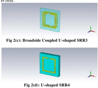
Fig 2(c): Broadside Coupled U-shaped SRR3
Fig 2(d): U-shaped SRR4
Metallic inclusions are made of copper with the thickness of 0.035mm. The same gap distance g=0.8mm and the same metal strip width w=0.5mm are used in all these different unit cells. The length of the upper and lower rings are 7mm and 5mm respectively.
Fig 2(e): Broadside Coupled U-shaped SRR5
Fig 2(f): U-shaped SRR6
III.
SIMULATION RESULTS
Najuka Hadkar Int. Journal of Engineering Research and Applications
www.ijera.com
ISSN : 2248-9622, Vol. 5, Issue 5, ( Part -4) May 2015, pp.11-14
www.ijera.com 13 | P a g e Fig 3(a): Magnetic Spectra for fig.2(a) arrays
Fig 3(b): Magnetic Spectra for fig.2(b) arrays
The topologies shown in Fig. 3(a), (b) have magnetic dips at 2.78GHz and 4GHz, respectively. The electrical size (u) of a resonator structure is found by the expression u = D / 0 where D is the
maximum linear dimension of the unit cell structure (i.e. D = 2 L for our square shaped unit cells with side length L) and 0 is the free space wavelength at
resonance frequency. Therefore, the electrical sizes of the BC-SRR1 and SRR2 are calculated to be 0.131 and 0.1885. In other words, the double-sided BC-SRR1 structure is electrically smaller than the singlesided SRR2 structure by 30.5 percent.
Fig 3(c): Magnetic Spectra for BC-SRR3 and SRR4
Similarly, the transmission spectra of the BC-SRR3(red curve) and SRR4 (green curve) structures are shown in Figure.3(c) with single magnetic resonance dips at 4.5 GHz and 5.9 GHz, respectively. Accordingly, the electrical sizes of the single-sided and double-sided topologies are calculated to be
0.2121 and 0.27 which means that the broadside-coupled structure is electrically smaller as compared to the SRR4 structure by 21.44 percent. Finally, transmission spectra of the inner ring topologies BC-SRR5( red curve) and BC SRR6 (green curve) are shown in Figure 3(d). Resonance dips of BC-SRR5 and SRR6 are observed at 4.65 GHz and 5.85 GHz, respectively, with the corresponding electrical sizes of 0.21917
Fig 3(d): Magnetic Spectra for BC-SRR5 and SRR6
and 0.2757. In other words, at the first resonance, the BC-SRR5 is electrically smaller than the SRR6 structure by 20.5 percent. Computed values of resonance frequencies and the corresponding electrical sizes of all structures are summarized in Table 1.
Structure Resonance Frequency(GHz)
Electrical Size -u BC-SRR1 2.78 0.131
SRR2 4 0.1885
BC-SRR3 4.5 0.2121
SRR4 5.9 0.27
BC-SRR5 4.65 0.21917 SRR6 5.85 0.2757
IV.
CONCLUSION
Najuka Hadkar Int. Journal of Engineering Research and Applications
www.ijera.com
ISSN : 2248-9622, Vol. 5, Issue 5, ( Part -4) May 2015, pp.11-14
www.ijera.com 14 | P a g e
V.
ACKNOWLEDGMENTS
Any project work that has achieved its objective is solely due to cumulative efforts taken by everyone in that project. So, I would like to thank my project guide, Prof. Santosh Jagtap for continuous encouragement, invaluable supervision and inspired guidance offered.
REFERENCES
[1]. "A New Design of a Band pass Filter at 2.45 GHz Based on Microstrip Line Using the Property of the Double Negative Metamaterials", HananeNASRAOUI1, Ahmed MOUHSEN2, Jamal EL AOUFI3 1,2,3LaboratoryIMMII FST Settat University Hassan1 Settat, Morocco
[2]. V. G. Veselago, “The electrodynamics of
substances with simultaneously negative values of e and ,” Sov. Phys.-Usp., 10, 1968, pp. 509–514
[3]. "Design of a Novel Two-Rectangular U-Shaped Double Negative Metamaterial", Anik Mallik, Sanjoy Kundu, Md. Osman Goni
[4]. Alici, K. B., F. Bilotti, L. Vegni, and E. Ozbay, “Miniaturized negative permeability materials,” Appl. Phys. Lett., Vol. λ1, 071121(1)–(3), 2007
[5]. Ziolkowski, R. W., “Design, fabrication, and
testing of double negative metamaterials,” IEEE Trans. Antennas Propag., Vol. 51, No. 7, 2003.
[6]. E. Ekmekci, K. Topalli, T. Akin and G. Turhan-Sayan, “A tunable multi-band metamaterial design using microsplit SRR structures,” Opt. Express, 17(18), 200λ, pp.16046-16058
[7]. Y. Yuan, C. Bingham, T. Tyler, S. Palit, T. H. Hand, W. J. Padilla, D. R. Smith, N. M. Jokerst, and S. A. Cummer “Dual-band planar electric metamaterial in the terahertz regime ,’’ Opt. Express, 16(13), 2008, pp. 9746-9752
[8]. E. Ekmekci, G. Turhan-Sayan, “Comparative investigation of resonance characteristics and electrical size of the double-sided SRR, BC-SRR and conventional SRR type metamaterials for varying substrate parameters, ”Progress In Electromagnetics Research B, 12, 2009, pp.35-62.
[9]. "Miniaturization of U-Shaped Multi-Band Metamaterial Structures", Oznur Turkmen1,2, Evren Ekmekci1,3, and Gonul Turhan-Sayan1
[10]. O. Turkmen, E. Ekmekci, G. Turhan-Sayan, “Parametric investigation of a new multi -band metamaterial design: U-shaped
multiple ring magnetic resonators, ’’IEEE International Symposium on Antennas and Propagation, Washington, USA, July 2011, submitted.
[11]. O. Turkmen, E. Ekmekci, G. Turhan-Sayan, “A new multi-ring SRR type metamaterial design with multiple magnetic resonances,’’ Progress in Electromagnetic Research Symposium, Marrakesh, Morocco, March 2011,in press
[12]. J. B. Pendry, A. J. Holden, D. J. Robbins, and W. J. Stewart, “Magnetism from conductors and enhanced nonlinear phenomena,” IEEE Trans. Microw. Theory Tech., 47(11), 1999, pp. 2075–2084