Abstract— Chebyshev microstrip lowpass filters with improved performance, achieved by means of circular complementary split ring resonators (CSRR), are presented. CSRR particles exhibit frequency rejection bandwidths in the vicinity of their resonant frequencies that can be used to meliorate both selectivity and stopband in microstrip lowpass filters. Two configurations have been used: a stepped-impedance model and a configuration using open-circuited stubs. Microstrip filters having 5, 7 and 9 poles were designed and fabricated. Selectivity values up to 86 dB/GHz and suppression levels reaching 60 dB in the stopband were obtained. The filters have cutoff frequency around 2 GHz and rejection band up to 10 GHz. The insertion of the designed CSRR resonators in the ground plane of the filters removes all the transmission spurious observed in the analyzed frequency band. No considerable variation in the passband group delay is observed in the CSRR-based lowpass filters. A comparison is made among the filters designed in this and other referenced works, considering their number of poles and size. The measured results are in good agreement with the simulated ones. The presented filters can be candidates for applications using the VHF, UHF and L bands, being also very effective in the rejection of the S and C bands. Applications that demand the rejection of the first half of the X band can also use the filters detailed in this paper.
Index Terms— Complementary split ring resonators, Microstrip filters, Microwave, Selectivity.
I. INTRODUCTION
Filters are important elements in many radiofrequency/microwave applications. Wireless
Communications, for instance, continue to impose strict filter design requirements, demanding
lightweight structures having high performance and reduced dimensions and cost [1]. An alternative
to planar structures is fabricating them using microstrip technology. Improvements in performance for
microstrip lowpass filters can be obtained using higher degree structures [2].
The use of complementary split ring resonators (CSRR), first presented by Falcone et al. [3], is an
Sharp Rejection and Wide Stopband
Microstrip Lowpass Filters using
Complementary Split Ring Resonators
I. F. da Costa
Federal Institute of Rio Grande do Norte (IFRN)- BR 406, Km 145, CEP: 59000-000, Ceará-Mirim/RN - Brazil, [email protected]
A. L. P. S. Campos
Federal University of Rio Grande do Norte (UFRN) - Av. Sen. Salgado Filho, 3000, CEP: 59072-970, Natal/RN - Brazil, [email protected]
A. Gomes Neto
Brazilian Microwave and Optoelectronics Society-SBMO received 27 Nov 2017; for review 03 Dec 2017; accepted 08 Mar 2018
option to meliorate the selectivity of microstrip filters, as well as to eliminate undesired transmission
spurious. As a consequence, this method can wide the stopband of microstrip filters [4], [5].
The CSRR resonator is a negative image of the split ring resonator (SRR), proposed by Pendry et
al. [6]. SRRs and CSRRs have a dual relation. CSRRs behave as particles able to produce negative
values of permittivity ε in the vicinity of their resonance [3].
This work presents Chebyshev microstrip lowpass filter designs which have their responses
improved by means of CSRRs. The resonators were entailed on the ground plane of the filters. These
particles were properly polarized by the microstrip sections of the filters. In order to verify these
results, traditional microstrip lowpass filter having n = 5, 7 and 9 poles have been designed and
fabricated. Stepped-impedance and open-circuited stubs lowpass filters were used as microstrip
configurations.
II. MICROSTRIP LOWPASS FILTERS:DESIGN AND ANALYSIS
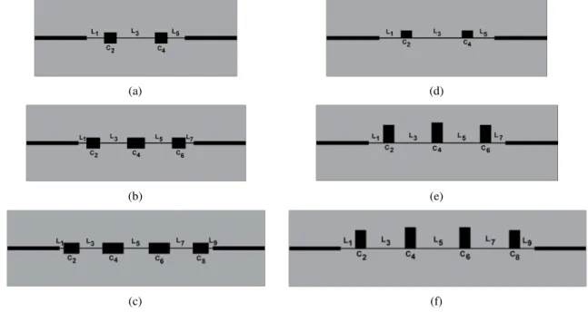
In Fig. 1, the lowpass filter configurations used in this paper are shown. Two configurations have
been chosen. The first one, known as stepped-impedance, uses high-impedance microstrip lines to
approximate the inductors (L), whereas the capacitors (C) are built using low-impedance microstrip
lines. The second configuration uses open-circuited stubs to fabricate the capacitors, maintaining the
high-impedance lines to approximate the inductors [1], [2].
The formulations in [1] have been used to design the dimensions of the microstrip sections for each
filter. The specifications for the structures are: cutoff frequency (fc = 2 GHz), filter order n (n = 5, 7
and 9), frequency response (Chebyshev, with passband ripple = 0.01 dB), and source/load impedance
Z0(= 50 Ω).
(a) (d)
(b) (e)
(c) (f)
Fig. 1. Microstrip lowpass filters. Stepped-impedance configuration: (a) F1, order n = 5; (b) F3, order n = 7 and (c) F5, order
n = 9. Configuration using open-circuited stubs: (d) F2, order n = 5; (e) F4, order n = 7 and (f) F6, order n = 9.
F4 and F6) are the ones using open-circuited stubs. The low-impedance and high-impedance lines
have, respectively, characteristic impedances of 24 Ω and 100 Ω. Access lines (λg/4 long) of 50 Ω
have been used [1]. The filters have been designed and fabricated on a FR-4 (εr = 4.4; thickness = 0.8
mm) laminate. A standard photo etching technique was used to fabricate the structures. Table I
comprises the width (W) and length (l) of the microstrip sections for each filter, shown in Fig. 1. The
fabricated filters are shown in Fig. 2.
TABLE I. DIMENSIONS (IN MM) OF THE MICROSTRIP SECTIONS OF THE FILTERS
Filter Dim. L1 C2 L3 C4 L5 C6 L7 C8 L9
F1 (5-pole) Fig. 1(a)
Width (W) 0.35 6.79 4.41 5.00 0.35 15.02 4.41 5.00 0.35
6.79 - - - - Length (l)
F2 (5-pole) Fig. 1(d)
Width (W) 0.35 8.36 4.41 3.11 0.35 19.33 4.41 3.11 0.35
8.36 - - - - Length (l)
F3 (7-pole) Fig. 1(b)
Width (W) 0.35 3.09 4.41 5.39 0.35 10.60 4.41 7.03 0.35 10.60 4.41 5.39 0.35
3.09 - - Length (l)
F4 (7-pole) Fig. 1(e)
Width (W) 0.35 5.61 4.41 7.36 0.35 14.56 4.41 8.30 0.35 14.56 4.41 7.36 0.35
5.61 - - Length(l)
F5 (9-pole) Fig. 1(c)
Width (W) 0.35 1.59 4.41 6.32 0.35 8.99 4.41 8.38 0.35 9.89 4.41 8.38 0.35 8.99 4.41 6.32 0.35 1.59 Length (l)
F6 (9-pole) Fig. 1(f)
Width (W) 0.35 5.74 4.41 7.50 0.35 15.40 4.41 8.59 0.35 17.28 4.41 8.59 0.35 15.40 4.41 7.50 0.35 5.74 Length (l)
(a) (b)
Fig. 2. Photographs of the fabricated microstrip lowpass filters: (a) Stepped-impedance configuration; (b) configuration using open-circuited stubs to realize the capacitors.
The filters were measured using an Agilent EN5071C vector network analyzer. Simulated and
measured results of the S11 and S21 parameters of the lowpass filters are shown in Fig. 3. The
simulated results were performed using an Ansoft HFSS v13 computational tool. As it can be seen in
Fig. 3, the measured and simulated results are overall in good agreement. The filters present values of
insertion loss in the passband around 1 dB. A reason for this can be attributed to the lossy FR-4
substrate used, along with the losses due to welding and the insertion of connectors and cables in the
measurement setup.
Brazilian Microwave and Optoelectronics Society-SBMO received 27 Nov 2017; for review 03 Dec 2017; accepted 08 Mar 2018
these conventional filters has been improved in consonance with the increase in the degree n of the
filters. Nevertheless, they have a slow transition between the 3 dB cutoff frequency, fc, and the 20 dB
stopband frequency, fs. The width of this transition is frequently referred as transition bandwidth
(BWt). Besides this limitation, it can be seen that the filters have undesired transmission spurious
within the frequency band under consideration (up to 10 GHz). The next section presents the CSRR
insertion procedure in order to improve the performance of these filters.
(a) (c) (e)
(b) (d) (f)
Fig. 3. Simulated and measured S parameters of the traditional filters: F1 (a), F2 (b), F3 (c), F4 (d), F5 (e) and F6 (f). Fig. 1 and Table I detail, respectively, the layout and the dimensions of each filter.
III. CSRR-BASED MICROSTRIP LOWPASS FILTERS
The lowpass filters described in the previous section had their ground planes modified by the
insertion of circular CSRR resonators. The configuration of a circular CSRR and its relevant
dimensions are shown in Fig. 4. The modified lowpass filters are depicted in Fig. 5.
Fig. 4. Configuration and relevant dimensions of a circular CSRR. The metal parts are depicted in grey.
The relevant dimensions of the CSRRs used in this paper are organized in Table II, as well as their
resonant frequencies. These values have been calculated using the model in [7]. The fabricated
modified ground planes are shown in Fig. 6. The CSRR resonators on the ground planes are aligned
with the center of their respective microstrip lines, except for those in the extremities, which are 7 mm
(a) (d)
(b) (e)
(c) (f)
Fig. 5. CSRR-based microstrip lowpass filters. The microstrip sections of the filters are depicted in black and the metallization of the ground plane is depicted in grey.
TABLE II.CSRR DIMENSIONS FOR THE FILTERS DEPICTED IN FIG.5.
Filter CSRR radius (mm) c (mm) d (mm) f0 (GHz)
F7 (Fig. 5a)
1/2/3 5.0/4.0/5.5 1.0 1.0 3.2/4.5/2.8 4/5 3.8/3.6 0.5 1.0 4.0/4.4
F8 (Fig. 5d)
1/2 5.0/4.6 1.0 0.5 2.7/3.1 3/4/5/6 4.6/4.1/4.1/3.9 0.8 0.5 2.9/3.4/3.4/3.6
F9 (Fig. 5b)
1/2 5.0/4.8 1.0 0.5 2.7/2.9 3/4/5/6 3.2/3.5/3.5/3.7 0.5 0.5 4.3/3.8/3.8/3.5
F10 (Fig. 5e)
1/2 5.0/4.6 1.0 0.5 2.7/3.0 3/4 4.0/3.6 0.5 0.5 3.2/3.7
F11 (Fig. 5c)
1/2 5.0/4.9 1.0 0.5 2.7/2.8 3/4 4.8/4.7 0.5 0.5 2.5/2.6
F12 (Fig. 5f)
1/2 4.9/4.9 1.0 0.5 2.8/2.8 3/4 3.6/3.6 0.5 0.5 3.7/3.7
(a) (b)
Brazilian Microwave and Optoelectronics Society-SBMO received 27 Nov 2017; for review 03 Dec 2017; accepted 08 Mar 2018
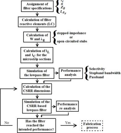
A flowchart depicting the design procedure used to obtain the CSRR-based microstrip lowpass
filters is shown in Fig. 7. As it can be seen, after the simulation of the initial lowpass filter, the
process of insertion the CSRR resonators repeats until the intended performance parameters are
reached. The performance parameters mentioned in Fig. 7 will be clarified in the next section.
Fig. 7. Design procedure used to obtain the CSRR-based microstrip lowpass filters.
IV. RESULTS
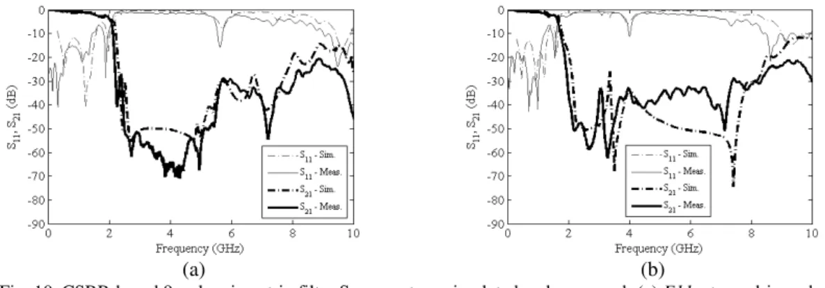
Simulated and measured S11 and S21 results (in dB) of the designed CSRR-based lowpass filters are
shown in Fig. 8, Fig. 9 and Fig. 10. A good agreement is observed between the simulated and
experimental responses. The results were analyzed considering the experimental values. A
comparison between the CSRR-based 5-pole microstrip lowpass filter results is shown in Fig. 8.
(a) (b)
According to Fig. 8(a), filter F7 has a 3 dB cutoff frequency of 1.95 GHz. The attenuation of this
filter drops to 20 dB at 2.44 GHz. The 3dB cutoff frequency of filter F8, whose response is shown in
Fig. 8(b), is 1.97 GHz. The rejection of this filter occurs at 2.17 GHz. Consequently, F8 is a more
selective filter than F7. Both filters have values of insertion loss in the passband around 1.1 dB. Table
III contains the values of the 3 dB cutoff frequency (fc), stopband frequency (fs) and selectivity (ξ) of the filters. The calculation of ξ follows the expression (1), defined in [8]:
c s
1 2
f f
α α ξ
(1)
where α2 and α1 represent, respectively, the 20 dB and 3 dB attenuation points.
TABLE III. CUTOFF FREQUENCY, STOPBAND FREQUENCY AND SELECTIVITY OF THE LOWPASS FILTERS.
Filter fc (GHz) fs (GHz) ξ (dB/GHz)
Sim. Meas. Sim. Meas. Sim. Meas.
F1 2.54 2.44 - - - -
F2 2.74 2.57 - - - -
F3 2.39 2.58 3.05 3.42 25.84 20.19
F4 1.88 1.88 2.49 2.49 27.54 27.54
F5 2.42 2.42 3.03 3.03 27.69 27.69
F6 1.73 1.73 2.10 2.17 45.90 38.25
F7 2.02 1.95 2.49 2.44 36.24 34.43
F8 2.02 1.97 2.25 2.17 76.51 86.07
F9 2.05 1.85 2.32 2.12 61.82 61.82
F10 1.63 1.63 2.12 2.05 34.43 40.49
F11 2.00 1.92 2.27 2.15 62.59 76.54
F12 1.68 1.58 2.00 1.87 52.96 57.37
The responses for the 7-pole CSRR-based filters are shown in Fig. 9. Filters F9 and F10 have
cutoff frequencies of, respectively, 1.85 and 1.63 GHz. The rejection for these filters starts at 2.12 and
2.05 GHz, respectively. The values of insertion loss in the passband for F9 and F10 are around 1.2
dB. The selectivity values of these filters are presented in Table III.
(a) (b)
Brazilian Microwave and Optoelectronics Society-SBMO received 27 Nov 2017; for review 03 Dec 2017; accepted 08 Mar 2018
The responses for the 9-pole CSRR-based filters are depicted in Fig. 10. F11 and F12 have 3 dB
cutoff frequencies equal to 1.92 and 1.58 GHz, respectively. The corresponding frequency values for
the 20 dB attenuation points are 2.15 and 1.87 GHz. It is worth noticing that filter F11 presents an
excellent rejection band between 2.42 and 5.23 GHz, with a very high rejection level (> 50 dB). It can
be observed that the insertion loss in F11 and F12 is around 1.3 dB, considering the passband.
Different from the previous filters, these 9-pole CSRR-based filters present higher levels of ripple in
the passband, which can be a drawback.
(a) (b)
Fig. 10. CSRR-based 9-pole microstrip filter S parameters, simulated and measured: (a) F11: stepped-impedance configuration and (b) F12: open-circuited stubs configuration.
Comparing the results of the CSRR-based microstrip lowpass filters with the traditional ones (see
Table III and Figs. 8-10), it can be affirmed that the CSRR-based filters having 5 poles presents a
performance comparable (F7) or much more superior (F8) to the best result obtained by the traditional
filters (F5 and F6), which are 9-pole structures. This leads to a filter with an area reduction of
approximately 27%. The transmission spurious bands of the conventional microstrip lowpass filters
(see Fig. 3) were all removed due to the insertion of the designed CSRR resonators.
Table IV presents a performance comparison among some of the designed lowpass filters and other
referenced works. As it can be noticed, F8 has an excellent transition bandwidth of 200 MHz, and a
stopband bandwidth of 4fc. This result is quite satisfactory, considering that the procedure to design
this filter is considerably easier than the approaches described, for instance, to design the filters
presented in [5] and [9]-[13]. It is also shown a comparison among the sizes of the designed filters and
some references. The parameter λg, in Table IV, is the guided wavelength of a 50 Ω microstrip line at
the cutoff frequency of the filter, as stated in [5].
Finally, simulated and measured group delay results are shown in Fig. 11. Considering the filters
F11 and F8, which have the best performances (see Table IV), it can be seen that the experimental
group delay in the passband (< 2GHz) for both filters has no considerable variation, maintaining its
values up to 5 ns. The differences observed between the simulated and measured group delay curves
can be interpreted, firstly, as an outcome of the welding losses, present only in the fabricated filters.
Secondly, other losses, as those present in the use of connectors and cables, are also part only of the
experimental results. Some disturbances in the group delay curves are seen around the resonance
(a) (b)
Fig. 11. Simulated and measured group delay: (a) filter F11 and (b) filter F8.
TABLE IV. PERFORMANCE COMPARISON AMONG SOME OF THE PROPOSED FILTERS AND REFERENCED WORKS.
Reference
Cutoff
Frequency
(GHz)
Transition
Bandwidth
(GHz)
Stopband
Bandwidth
Size
(width x
length, in λg)
[5] 3.94 0.53 0.3fc ---
[9] 2.95 1.05 5.4fc ---
[10] 1.09 0.34 10fc 0.16 x 0.08
[11] 1.08 0.37 6fc 0.22 x 0.18
[12] 2.49 0.31 1.7fc ---
[13] 2.07 0.47 8.6fc ---
This work (F12) 1.58 0.30 5.1fc 0.29 x 1.14
This work (F9) 1.85 0.27 4.2fc 0.34 x 0.97
This work (F11) 1.92 0.22 4.1fc 0.35 x 1.19
This work (F8) 1.97 0.20 4fc 0.36 x 1.03
V. CONCLUSION
Chebyshev microstrip lowpass filters with improved selectivity and stopband are presented
in this work. The advantage of this approach is the possibility of maintaining the design
procedure of traditional microstrip lowpass filters, presented in many references, thus
keeping the dimensions of the structures. This work compares filters having 5, 7 and 9 poles,
presenting them with two configurations: stepped-impedance and open-circuited stubs. The
insertion of CSRR resonators on the ground plane of the microstrip lowpass filters leads to
selectivity values up to 86 dB/GHz, as well as the removal of undesired transmission spurious
observed in the analyzed frequency band. It is important to highlight that rejection levels
exceeding 60 dB in the stopband were obtained, considering frequencies up to 10 GHz. A
size reduction can be achieved using low order microstrip lowpass filters with CSRRs
Brazilian Microwave and Optoelectronics Society-SBMO received 27 Nov 2017; for review 03 Dec 2017; accepted 08 Mar 2018
The group delay observed in the filters keeps almost unaltered in the passband. Losses due
to welding and use of connectors and cables are present in the experimental results. The
filters in this paper can be used in applications using the VHF, UHF and L bands. For
instance, applications as satellite navigation and telecommunications use carriers having
frequencies within the L band (1-2 GHz). Also, if the rejection of the S and C bands is
required, the filters in this paper are good alternatives. Work is ongoing on the
miniaturization of the structures presented here.
REFERENCES
[1] J. -S. Hong, Microstrip Filters for RF/Microwave Applications. New Jersey: John Wiley & Sons, 2011.
[2] I. Hunter, Theory and Design of Microwave Filters. Cambridge: The Institution of Engineering and Technology, 2001. [3] F. Falcone, T. Lopetegi, J. D. Baena, R. Marqués, F. Martin, and M. Sorolla, "Effective Negative-ε Stopband Microstrip
Lines Based on Complementary Split Ring Resonators," IEEE Microw. Compon. Lett., vol. 14, no. 6, pp. 280-282, Jun. 2004.
[4] J. García-García, J. Bonache, F. Falcone, J. D. Baena, F. Martin, I. Gil, T. Lopetegi, M. A. G. Laso, A. Marcotegui, R. Marqués, and M. Sorolla, "Stepped-impedance Lowpass Filters with Spurious Passband Suppression," Electron. Lett., vol. 40, no. 14, pp. 881-883, Jul. 2004.
[5] A. Ali, M. A. Khan, and Z. Hu, "High Selectivity Lowpass Filter using Negative-ε Metamaterial Resonators," Electron. Lett., vol. 43, no. 9, pp. 528-530, Apr. 2007.
[6] J. B. Pendry, A. J. Holden, D. J. Robbins, and W. J. Stewart, "Magnetism from Conductors and Enhanced Nonlinear Phenomena," IEEE Trans. Microw. Theory Techn., vol. 47, no. 11, pp. 2075-2084, Nov. 1999.
[7] C. Saha, and J. Y. Siddiqui, "Theoretical Model for Estimation of Resonance Frequency of Rotational Circular Split-Ring Resonators," Electromagnetics, vol. 32, pp. 345-355, 2012.
[8] N. C. Karmakar, "Theoretical Investigations into binomial distributions of photonic bandgaps in microstripline structures," Microw. Opt. Technol. Lett., vol. 33, no. 3, pp. 191-196, May 2002.
[9] M. Challal, A. Boutejdar, M. Dehmas, A. Aznar, A. Omar, "Compact Microstrip Low-pass Filter Design with Ultra-wide Reject Band using a Novel Quarter-circle DGS Shape," ACES Journal, vol. 27, no. 10, pp. 808-815, Oct. 2012. [10]S. S. Karthikeyan, and R. S. Kshetrimayum, "Compact and Wide Stopband Lowpass Filter using Open Complementary
Split Ring Resonator and Defected Ground Structure," Radioengineering, vol. 24, no. 3, pp. 708-711, 2015.
[11]S. S. Karthikeyan, and R. S. Kshetrimayum, "Compact, Deep and Wide Rejection Bandwidth Low-pass Filter Using Open Complementary Split Ring Resonator," Microw. Opt. Techn. Lett., vol. 53, no. 4, pp. 845-848, Apr. 2011. [12]R. Y. Yang, et al., "Design of a Compact and Sharp Rejection Lowpass Filter with a Wide Stopband," J. Electromagn.
Waves Appl., vol. 26, no. 17-18, pp. 2284-2290, 2012.